1
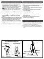
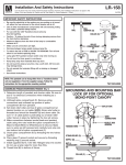
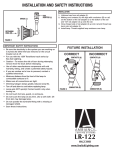
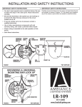
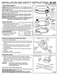
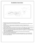
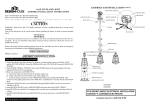
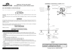
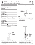
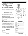
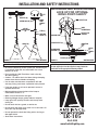
INSTALLATION AND SAFETY INSTRUCTIONS
RAIL
RAIL
ADAPTER (N)
SCREW COLLAR (E)
SPLICE
COMPARTMENT
(G)
*OUTLET
*BOX
GROUNDING AND MOUNTING BAR
LOCK UP FOR OPTIONAL
MONO-POINT CANOPY
*OUTLET BOX
MONOPOINT
CANOPY
(D)
WIRE
CONNECTORS
STEM (I)
SHIPPING
BREAK (S)
*OUTLET BOX
SCREWS
*GROUND WIRE
STRAIN RELIEF (O)
SHADE (H)
MOUNTING
BAR
(A)
LOCKWASHER
& HEXNUT (B)
NIPPLE
(C)
CANOPY
(D)
COLLAR (E)
FIGURE 1
*NOT INCLUDED
IMPORTANT SAFETY INSTRUCTIONS
• Be sure the electricity to the system you are working on
is turned off; either the fuse removed or the circuit
breaker set at off.
• For use with the 120V Transitions track series by
Sea Gull Lighting.
• Caution – To reduce the risk of burn during relamping
remove from the track before relamping.
• Use of other manufacturers components will void
warranty, listing, and create a potential safety hazard.
• If you are unclear as to how to proceed, contact a
qualified electrician.
• Minimum distance from the front of the lamp to
combustible surfaces is 8".
• Make sure all connections are tight.
• Dimming halogen lamps greatly reduces lamp life.
• Lamp gets HOT quickly! Contact switch only when
turning on.
• Do not touch hot lens, guard, or enclosure.
• Do not touch the lamp at any time. Use a soft cloth. Oil
from skin may damage lamp.
• Do not operate the luminaire fitting with a missing or
damaged shield.
• Save these instructions.
FIGURE 2
*NOT INCLUDED
NOTE: This pendant can be hung either from a Transitions Series
rail (not supplied) or from the supplied canopy. Follow the
instructions for the appropriate mounting method.
LR-105
062408
www.SeaGullLighting.com
ASSEMBLING PENDANT/SHORTENING PENDANT
LR-105
1. Determine length of pendant and shorten cable above the
splice compartment (G). Be sure to add 5" for electrical
connections when installing as a mono-point. Unthread top
of splice compartment (G). Set top half of splice
compartment (G) and strain relief collar at desired location.
NOTE Strain relief collar is threaded and should be
threaded up and down cable. Be sure 1/4" of cable jacket is
protruding out of strain relief collar. Secure in place by
tightening the set screws.
2. Assemble stem (I) together at shipping break (S) by holding
top half of stem (I) in place and threading socket half of the
stem (I).
3. To install shade (H), remove three prongs off of spider (V)
by unthreading. Install shade (H) and replace the three
prongs onto spider (V) so shade (H) rests evenly on the
spider (V).
4. Make connections between socket leads and pendant cable
using wirenuts inside the splice compartment (G) – Black to
Black/White to White/Ground to Ground. Make sure no
wires are left exposed and carefully tuck wires into bottom
half of splice compartment (G).
5. Close splice compartment (G) by threading the two halves
together.
6. Install lamp (K). Thread glass enclosure (J) over lamp (K).
FOR MONO-POINT INSTALLATION (Fig.2)
1. Remove rail adapter (N) by cutting wire below rail adapter
(N).
2. Slide collar (E), canopy (D), mounting bar (A), lockwasher &
hex nut (B), and nipple (C) to the top of the splice
compartment (G).
3. Install strain relief (O). Tighten strain relief set screw with a
flat head screwdriver.
4. Attach mounting bar (A) to outlet box using outlet box
screws (not supplied).
5. Make electrical connections,
a. House Black to Fixture Black
b. House White to Fixture White
c. House Ground to Green Ground Screw
Make sure no wires are left exposed and carefully tuck
wires into outlet box.
6. Raise canopy (D) to ceiling and secure in place by
threading collar (E) to nipple (C).
ATTACH PENDANT TO RAIL (Fig.3)
1. Unthread cap (R) from rail adapter (N).
2. Making sure contacts (Q) will align with conductors (P) on
rail, set the bottom of rail adapter (N) to the bottom of the
rail and “roll” rail adapter (N) up onto the rail.
3. Install fixture to rail by closing hinged side of rail adapter
(N) over rail and threading cap (R) back onto adapter (N)
tightly.
FIXTURE INSTALLATION
CORRECT
CONTACT (Q)
SPIDER (V)
INCORRECT
CONTACT (Q)
CAP (R)
SHADE (H)
SOCKET (M)
LAMP (K)
GLASS
ENCLOSURE (J)
CAP (R)
FIGURE 3
CONDUCTOR (P)
CONDUCTOR (P)
FIGURE 4