Transcript
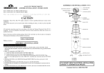
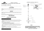
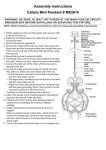
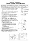
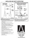
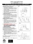
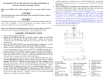
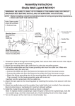
ASSEMBLY AND INSTALLATION (CONT.)
AJAX 3LT ISLAND LIGHT
ASSEMBLY/INSTALLATION INSTRUCTIONS
Item # 519744 (AJAX 3LT ISLAND LIGHT GAL)
Item # 519785 (AJAX 3LT ISLAND LIGHT BRZ)
Please read carefully and save these instructions, as you may need them at a later date.
MOUNTING SCREWS
JUNCTION BOX
CROSS BAR
GROUND SCREW
CEILING PLATE
BALL NUTS
SCREW HOLES
CAUTION
C
WARNING: Risk of Fire. Min 75ºC supply conductors. Consult a qualified electrician to ensure correct
installation.
Turn off the main power at the circuit breaker before installing the fixture, in order to prevent possible
shock.
STEMS
B
A
FIXTURE SCREWS
WIRE NUTS
GENERAL
All electrical connections must be in accordance with local and National Electrical Code (N.E.C.)
standards. If you are unfamiliar with proper electrical wiring connections obtain the services of a
qualified electrician.
SHORT STEMS
Remove the fixture and the mounting package from the box and make sure that no parts are missing by
referencing the illustrations on the installation instructions.
Phillips screwdriver.
FIXTURE
TOOLS REQUIRED
ASSEMBLY AND INSTALLATION
LAMP HOLDER
Turn off the power at fuse or circuit breaker.
1. Gently take all parts out of the package, lay them on a smooth surface, unscrew the BALL NUTS
and the FIXTURE SCREWS. Attach the CROSS BAR to the JUNCTION BOX using (2) MOUNTING
SCREWS.
2. Attach SHORT STEMS to FIXTURE. Then, install STEMS based on the desired length of the item,
adding CEILING PLATE once finished.
3. Make wire connections with WIRE NUTS:
A - Connect the black wire from Fixture to the black supply wire.
B - Connect the white wire from Fixture to the white supply wire.
C - Attach the fixture ground wire to the CROSS BAR with the green GROUND SCREW. Then
connect it to the supply ground wire with a WIRE NUT. Carefully tuck wires back into the JUNCTION
BOX.
4. Attach the CEILING PLATE to the CROSS BAR through SCREW HOLES as shown, and secure it
with BALL NUTS.
5. Attach the IRON RACKS to the LAMP HOLDERS and secure them with SOCKET RINGS.
6. Install BULBS (not included). See relamping label at socket area or packaging for maximum allowed
wattage.
7. Attach the IRON RACKS (01) to the IRON RACKS as shown, and secure it with DECORATIVE
NUTS .
Turn on the power at fuse or circuit breaker.
IRON RACK
SOCKET RING
BULB (not included)
IRON RACK (01)
DECORATIVE NUTS
#519744
#519785
IF IN DOUBT ABOUT ELECTRICAL INSTALLATION,
CONSULT A LICENSED ELECTRICIAN.
Customer Service 1-800-558-8700