1
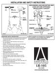
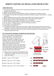
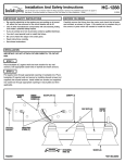
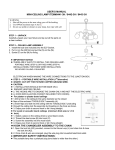
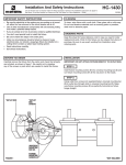
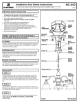
LR-150
Installation And Safety Instructions
Line art shown may not exactly match the fixture enclosed. However, the installation instructions do apply to this
fixture. Fill in Item Number on Carton and File This Sheet For Future Reference. ITEM#_______________
040909
ASSEMBLY
1. See fixture instruction sheet for disassembly of pendant before
installing glass.
2. Determine what part bag you are using.
SPIDER (A)
PART BAGS
PART BAG A – Figure 1
RETAINING
SCREWS (B)
Glass Supporter
PART BAG B – Figure 2
STEM
SUPPORT (C)
Support
PART BAG C – Figure 3
Socket Locator
Retaining Ring
SOCKET
FIGURE 2
PART BAG D – Figure 4
Socket Locator
Retaining Ring
Spider
Socket Locator
Retaining Ring
PART BAG E – Figure 5
Glass Supporter
1. Bring the socket and stem through the top of glass. Bring spider
(A) over socket and secure by threading retaining screws (B)
through glass into spider (A).
2. Set support at desired location on stem and secure by tightening
set screw with allen wrench.
PART BAG F – Figure 6
Spider
PART BAG G – Figure 7
Glass Supporter
CABLE (A)
CABLE (A)
STEM (B)
GLASS
SUPPORT (C)
SOCKET
LOCATOR (D)
RETAINING
RING (C)
STEM (B)
SOCKET (E)
FIGURE 1
1. Determine desired location for glass to hang. Place glass
support (C) onto stem (B) and secure in place by tightening set
screw with supplied allen wrench.
2. Pull cable (A) through glass and place glass on glass support (C)
so it rests evenly.
FIGURE 3
1. Remove retaining ring (C) from socket locator (D) and set aside.
2. Slide socket locator (D) onto stem (B). Secure the socket locator
(D) at desired height with supplied allen wrench.
3. Secure the threaded ring (C) to the socket locator (D).
4. Pull cable (A) from bottom of glass through top opening in glass.
5. Glass should rest on retaining ring.
LR-150 (continued)
CABLE (A)
SPIDER (C)
SOCKET
LOCATOR (E)
RETAINING
RING (D)
SPIDER (A)
SOCKET (B)
STEM (B)
SOCKET
FIGURE 4
FIGURE 6
1. Remove retaining ring (D) from locator (E) and set aside.
2. Slide the socket locator onto stem (B). Secure the socket locator
(E) with the allen wrench to the desired length on the stem (B).
3. Secure the threaded ring (D) to the socket locator (E).
4. Slide spider (C) onto stem (B) and fit on top of retaining ring (D).
5. Pull cable (A) from bottom of glass through top opening in glass.
1. Spider (A) should rest on top of socket (B). You will need to
remove wiring connections at splice compartment (if applicable)
or remove wire from mono point canopy.
2. Place glass on spider (A) so it rests evenly.
CABLE (A)
CABLE (A)
STEM (C)
GLASS SUPPORT (B)
SOCKET LOCATOR (E)
RETAINING RING (D)
GLASS SUPPORT (B)
STEM (C)
FIGURE 5
1. Slide glass support (B) through cable (A) and onto stem (C).
2. Pull cable (A) through bottom of glass so glass rests securely in
glass support (B)
FIGURE 7
1. Remove retaining ring (D) from socket locator (E) and set aside.
2. Slide the socket locator (E) onto stem (C). Secure the socket
locator (E) with the allen wrench to the desired length on the stem
(B).
3. Secure the retaining ring (D) to the socket locator (E).
4. Rest glass support (B) on top of socket locator (E) and retaining
ring (D).
5. Place glass on top of glass support (B).
FINAL ASSEMBLY
1. Reassemble pendant according to pendant instructions.