1
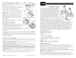
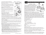
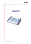
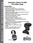
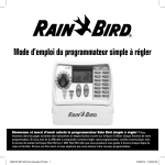
ANTI-SIPHON VALVE
OPERATION MANUAL: DAS-075 / ASVF 3/4” DAS-100 / ASVF 1”
For use with all standard sprinkler controllers with 24 volt AC output. The DAS / ASVF valves are diaphragm anti-siphon valves
with flow control and atmospheric vacuum breaker.
NOTE: These Rain Bird valves are designed for use with static water
pressures of a MAXIMUM of 150 PSI. For higher pressures, a pressure
regulator should be installed. These valves are for outdoor watering use
only.
For dirty water systems-using wells, lakes, ditches, etc. for your
water supply, be sure to install a 100 mesh (or finer) wire filter or
screen filter before the electric valves. For use in cold water, less
than 110°F (43.3°C), applications only.
ANTI-SIPHON VALVES FOR BACKFLOW PREVENTION
The DAS/ASVF models meet or exceed most building code requirements for
connecting a sprinkler system to a city water supply.
#1
These valves prevent the possibility of back siphoning of water from sprinkler
lines into the drinking water.
Wires to Controller
Test this connection
for water tightness
before attaching
outlet pipe.
The anti-siphon valves must be installed at least 6 inches above the highest
sprinkler or elevated piping in the circuit to meet most codes, (See Diagram 1).
(Consult local building code.)
CAUTION: Do not use this anti-siphon valve as a main line backflow device,
nor as a master valve. It is not designed nor approved to be under constant water pressure on both sides of valve. This valve must not be operated continuously for more than twelve (12) hours. Do not install any other valves down
stream. If installed incorrectly with constant pressure on both sides of valve, it is
possible that the valve will fail or burst.
6”
6”
The valve
must be
mounted at
least six
inches above
the highest
sprinkler on
the circuit.
Outlet to Sprinklers
Inlet
HOW TO SELECT THE RIGHT VALVE SIZE
The valve size (3/4" or 1 ") is determined by the water flow (measured in gallons per minute, or GPM) of the main line
or the sprinkler circuit.
3/4" VALVES: 13 GPM or less.
1" VALVES: 14 GPM or more.
1 " valves and pipes allow longer runs and more sprinkler heads per circuit, as well as potentially reducing the total
number of valves required.
ASSEMBLY OF SPRINKLER VALVES TO PIPE
A sprinkler system is made up of one or more groups of sprinklers (called circuits) each operated by its own control
valve. Study the illustrations and follow the instructions for proper assembly.
1
1. Before connecting and testing the assembly, thoroughly flush the main line to prevent debris from damaging the valves.
2. On the inlet side of the control valve, use galvanized
steel pipe or thick-walled, Schedule 40 PVC, white
plastic pipe, as this pipe is under constant pressure. On
the outlet side of the control valve, thin-walled PVC
pipe or flexible potyethylene pipe may be used.
3. To assure a watertight connection, use only one to two
turns of Teflon tape on the threaded valve-to-pipe connections. DO NOT USE PIPE SOLVENT (CEMENT)
OR PIPE DOPE. THIS MAY DAMAGE THE VALVE.
DO NOT OVER-TIGHTEN. Screw adapters into place
finger tight. Tighten adapters one to two additional
turns.
4. Install a master shutoff valve before all electric valves,
so that the water can be conveniently turned off if a
valve needs servicing.
TO OPERATE YOUR VALVE ELECTRONICALLY, BE SURE THE SOLENOID IS TURNED
ALL THE WAY TO THE CLOCKWISE POSITION.
CONNECTION, TESTING AND WIRING THESE
VALVES
1. Shut off the water main or the master shutoff valve and
connect the valve or valve assembly to the main supply
pipe. Be sure the water lines are flushed and clean.
2. Test the pipe and valve connections for water tightness
as follows:
A. Turn the flow control clockwise (down) to off before
turning on the water supply.
B. Turn on the water and check for leaks.
3. Now complete the hookup by connecting the outlet pipes
from the valves to the sprinklers.
5. When grouping valves, allow sufficient spacing between valves to unscrew the valve from the pipe (about
6 inches).
6. Do not connect the outlet side (piping to sprinkler
heads) without first testing for leaks. If the outlet side is
connected and there is a leak, the pipe would have to
be cut in order to tighten the connection.
4. Set flow control adjustment before making wiring connections.
5. WIRE CONNECTIONS (Diagram 2). Use 18 gauge wire
to connect the wires to the controller. Wiring that
is to be buried alongside the pipes should be APPROVED for UNDERGROUND use. For all splices, use
water tight connectors. (Do not exceed 600 ft.)
VALVE OPERATION
Each valve has two wires. Either one may serve as the
“HOT” wire which is connected directly to a station output terminal in the controller. The other wire is
"COMMON" and may be joined to the common wires of
other valves with one wire running to the common terminal of the controller. Check operation using the controller.
Your Rain Bird valve offers two features with which you
should become familiar.
FLOW CONTROL: This feature allows you to control the
amount of water going to your sprinklers. To allow more
water through the valve, turn the black knob counter
clockwise UNTIL RESISTANCE IS FELT. This is fully
open position.
To reduce the amount of water, turn the black knob clockwise. If you keep turning, you can turn the valve all the
way off. In this case, the valve will not open.
#2
Controller Terminals
Common
MANUAL CONTROL: This allows you to override your
automatic controller and turn your sprinklers on AT THE
VALVE. The valve can be turned on manually with the
external bleed screw or with the internal solenoid bleed.
The solenoid (block cylinder with wires) is wired to your
controller and turns the valve off and on electronically.
Common
Wire
To operate manually with the internal bleed, turn the
solenoid 1/4 turn counterclockwise; this opens the valve.
The sprinklers will continue to run until you turn the
solenoid back in the clockwise direction(snugly), but do
not over-tighten.
Valve
Solenoid
To turn on (open) the valve with the external bleed, turn
the external bleed screw counterclockwise, 1/2 turn. Water will exit the external bleed while the valve is on. To
turn off the valve, turn the external bleed screw clockwise
until snug. Do not over-tighten.
2
4
3
Hot
Wires
2
1
4a. Diaphragm filter clogged. Use manual, external bleed
to flush valve. If this does not improve operation, remove top of valve (6 screws). Remove diaphragm and
inspect filter for debris. (Check 4b at the same time.)
Clean diaphragm filter and reassemble valve.
REPAIR KITS
Two types of repair kits are available (Diagram 3)
1.
2.
SRK-ASV Solenoid Replacement Kit. The SRK-ASV
will replace a defective solenoid on models DAS075/ASVF and DAS-100/ASVF.
4b. Diaphragm/valve seat fouled or damaged. Remove diaphragm and inspect diaphragm and valve seat for
damage or debris. Clean or replace diaphragm and reassemble valve.
B. Valve Won't Turn On Manually
DRK-ASV Diaphragm Replacement Kit. The DRKASV will replace a defective diaphragm on models
DAS-075/ASVF and DAS-1 00/ASVF.
For technical assistance call us at 1-800-RAIN-BIRD.
1. Flow control turned off. Check by turning black knob
counterclockwise until encountering resistance. Do not
force beyond point of resistance. Turn knob back clockwise, approximately one half turn.
2. Water supply off at meter or system control shut-off.
(Check this first by manually bleeding the valve with
either bleed screw or by turning solenoid counterclockwise).
3. Blocked ports. If valve will turn on with manual, external bleed screw but NOT by turning the solenoid for internal bleed, remove the solenoid (rod check solenoid
cavity for debris. Visually check small square hole at
edge of cavity and carefully run a straightened wire
through the center round hole to clear tube of possible
debris. Take care not to scratch sides of center port
tube as any change in size can affect valve operation.
#3
Solenoid
Replacement Kit
SRK-ASV
Part # 170277
Diaphragm
Replacement
Kit
DRK-ASV
C. Valves Won't Turn on Electronically (with controller)
1. Controller settings incorrect. Check programming, start
times, run times and day schedules.
2. If none of the valves are working, check the common
(ground) wire for a tight connection or damage. If only
one or part of the valves do not work, check wiring for
damage (staples, nails, cracks) between controller and
valve location.
3. Check all of reasons in Section B.
4. Faulty solenoid. Turn off water supply. Switch solenoid
with one from a nearby operational valve. If original
valve works with second solenoid, replace original
solenoid. (Install water-tight wire connections on all
valves at this time to avoid future solenoid shorts and/
or failures.)
5. Controller not supplying power to valve/valves. Check
fuse. If blown, replace fuse with same size. (Do not
change sizes. A different size fuse will damage controller during operation and will void the warranty.) If
fuse is OK, either use a volt/ohm meter to check controller output (24 VAC) at each terminal screw (station/
valve connection) OR disconnect an operating solenoid
from a valve and take it to the controller. Attach one
wire to the "C" terminal (common/ground) and attach
the other wire to the station which is not working. Activate the controller in manual start. The solenoid should
click (pull the plunger up into the solenoid tube) and it
may hum. (Continued on next page)
TROUBLESHOOTING GUIDE
A. Water Won't Shut Off (seeping or full flow)
1. Incorrect controller setting (check length of run time)
2. Loose solenoid (should be tight)
3. Loose bleed screw - check and tighten (finger tight
only)
3
5.
(Continued) If
nothing happens, (and the controller is still under warranty) you should either return your controller to the
store or call your installer. If it's no longer under warranty, you will need to purchase a new controller. Be sure to
install
water-tight connectors on your wiring and a surge protector (if you live in areas highly prone to lightning). This
will help to avoid future problems.
APPROVED VALVE GROUP INSTALLATION USING PVC PIPE AND FITTINGS
Diaphragm Automatic
Anti-Siphon control valves
Connecting pipe
from water source
Service
Line to
House
Install valves
at least 6”
above
the highest
sprinkler
PVC Pipe
Service
Line
from
Street
To backyard
control valves
To
Control
Valves
Connecting pipe and fittings
to be the same size as the
largest control valve in the
group
Shutoff
Valve
Compression
Tee
Water
Meter
To Sprinklers
Call 1-800-RAIN-BIRD
We’re Here to Help
Customer Support Center u 6991 East Southpoint Rd., Bldg. #1 u Tucson, AZ 85706
1-800-RAIN-BIRD u (520) 434-6290 FAX
® Registered Trademark of Rain Bird Sprinkler Mfg. Corp.
© Copyright 1994 Rain Bird Sprinkler Mfg. Corp. 11/94
4