1
deltawaveC-P
User manual
User manual
deltawaveC-P
portable Ultrasonic flow measuring
systec Controls Mess- und Regeltechnik GmbH
www.systec-controls.de
1/139
V.1.13
deltawaveC-P
User manual
Table of content
Table of content .............................................................................................................................................................. 2
1.
About this manual ............................................................................................................................................. 5
2.
Approvals / CE.................................................................................................................................................. 6
3.
Measuring Principle .......................................................................................................................................... 8
4.
deltawaveC-P and components ...................................................................................................................... 10
4.1.
deltawaveC-P flow transmitter ................................................................................................................... 11
4.2.
Ultrasonic transducers ............................................................................................................................... 11
4.3.
Mounting material and accessories............................................................................................................ 13
4.3.1.
Signal cables ......................................................................................................................................... 13
4.3.2.
Spacer bar for transducer mounting ...................................................................................................... 13
4.3.3.
Mounting chains for transducer mounting ............................................................................................. 14
4.3.4.
Coupling grease .................................................................................................................................... 15
4.3.5.
PT100 Temperature sensors................................................................................................................. 15
4.3.6.
4-20mA analogue output cable.............................................................................................................. 16
4.3.7.
cable for relay/ipulse ............................................................................................................................. 16
4.3.8.
Power adapter 100-240V, 47-63Hz, 1A................................................................................................. 16
4.4.
Interfaces of deltawaveC-P ........................................................................................................................ 17
4.5.
Scope of supply basis package.................................................................................................................. 19
4.6.
Saftey instructions...................................................................................................................................... 20
5.
Operating ........................................................................................................................................................ 21
5.1.
Control Buttons .......................................................................................................................................... 21
5.2.
How to navigate ......................................................................................................................................... 22
6.
Get started ...................................................................................................................................................... 23
6.1.
Basic settings, main menu, navigation ....................................................................................................... 23
6.1.1.
Setting language ................................................................................................................................... 23
6.1.2.
Navigation in main menu (flow 1) .......................................................................................................... 24
6.1.3.
Setting the time and date ...................................................................................................................... 26
6.1.4.
The status bar ....................................................................................................................................... 27
7.
Preparing for measurement ............................................................................................................................ 29
7.1.
Required straight runs................................................................................................................................ 29
7.2.
Mounting positions for transducers ............................................................................................................ 31
7.2.1.
Basics on the mounting of ultrasonic transducers ................................................................................. 31
7.2.2.
Mounting ultrasonic transducers on horizontal piping............................................................................ 31
7.3.
Mounting ultrasonic transducers ................................................................................................................ 33
7.3.1.
V-Mode.................................................................................................................................................. 33
7.3.2.
W- Mode................................................................................................................................................ 34
7.3.3.
Z- Mode................................................................................................................................................. 34
8.
Measuring with deltawaveC-P ........................................................................................................................ 35
8.1.
Parameterization ........................................................................................................................................ 36
8.2.
What needs to be parameterized? ............................................................................................................. 36
8.3.
Parameterizing with Quick Setup ............................................................................................................... 38
8.4.
Mounting distance ..................................................................................................................................... 45
8.4.1.
V-mode and W-mode ............................................................................................................................ 45
8.4.2.
Installation at Z- Mode........................................................................................................................... 47
8.4.3.
Introduction in ultrasonic transducer mounting ...................................................................................... 48
8.4.4.
Mounting in V-mode or W-mode............................................................................................................ 50
8.4.5.
Fix transducers at pipe using mounting chains ..................................................................................... 51
8.4.6.
Mounting the ultrasonic transducers based on the Z method................................................................ 52
8.5.
Edit parameters.......................................................................................................................................... 56
8.6.
Zero Setting ............................................................................................................................................... 60
8.6.1.
Zero calibration starting in "Flow1” menu .............................................................................................. 60
8.6.2.
Zero calibration using the main menu: .................................................................................................. 61
8.6.3.
Deleting the zero value.......................................................................................................................... 62
8.7.
Heat measurement..................................................................................................................................... 63
8.7.1.
Introduction ........................................................................................................................................... 63
8.7.2.
Installing the PT100............................................................................................................................... 65
8.7.3.
Zero setup of temperature sensors ....................................................................................................... 66
8.7.4.
Absolute thermal output measurements (absolute measurement) with PT100 ..................................... 67
9.
Measuring windows of deltawaveC-P ............................................................................................................. 69
9.1.
The main display „flow1“ ................................................................................................................................. 69
9.2.
Measuring window "Flow 2“ ....................................................................................................................... 71
9.3.
Measuring window "Heat“ .......................................................................................................................... 71
9.4.
Selecting the physical units....................................................................................................................... 72
9.4.1.
Selecting the flow unit ........................................................................................................................... 73
9.5.
Selecting the physical unit for the totalizer ................................................................................................. 74
9.5.1.
Selecting the physical unit for thermal output ........................................................................................ 75
9.5.2.
Selecting the physical unit for heat quantity .......................................................................................... 75
systec Controls Mess- und Regeltechnik GmbH
www.systec-controls.de
2/139
V.1.13
deltawaveC-P
User manual
9.6.
Saving, loading and managing data ........................................................................................................... 76
9.6.1.
Logging data ......................................................................................................................................... 76
9.6.2.
Time controlled data logging ................................................................................................................. 76
9.6.4.
Save/load/edit parameters .................................................................................................................... 81
10.
Reading data on the computer........................................................................................................................ 83
10.1.
Exporting data in MS Excel ........................................................................................................................ 84
11.
Parameterize I/O............................................................................................................................................. 86
11.1.
Parameterizing the 4 mA to 20 mA current outputs .................................................................................. 86
11.2.
Parameterize the Relay.............................................................................................................................. 91
Color coding of the relay output cable:................................................................................................................... 91
11.3.
Parameterize the Impulse Output .............................................................................................................. 94
11.4.
Calibrating flow .......................................................................................................................................... 96
11.5.
Calibrating the PT100 ................................................................................................................................ 97
12.
Systems Settings ............................................................................................................................................ 98
12.1.
Editing the time and date ........................................................................................................................... 98
12.2.
Modifying the display backlight .................................................................................................................. 99
12.3.
Change language..................................................................................................................................... 100
12.4.
Miscellaneous .......................................................................................................................................... 101
12.5.
Flow Damping .......................................................................................................................................... 102
12.6.
Flow Cut off.............................................................................................................................................. 102
12.7.
Zero Setting ............................................................................................................................................. 103
12.8.
System Setup-> "System information“ ..................................................................................................... 103
12.9.
Software Reset ........................................................................................................................................ 104
13.
Troubleshooting ............................................................................................................................................ 106
13.1.
Integrated sensor test function................................................................................................................. 107
14.
Troubleshooting ............................................................................................................................................ 109
14.1.
Diagnostic menu of deltawaveC-P ........................................................................................................... 112
14.1.1.
Oscilloscope / Auto-Window................................................................................................................ 112
14.1.2.
Diagnostic menu.................................................................................................................................. 127
14.2.
Software update ....................................................................................................................................... 131
15.
Media properties ........................................................................................................................................... 134
16.
Specifications................................................................................................................................................ 138
systec Controls Mess- und Regeltechnik GmbH
www.systec-controls.de
3/139
V.1.13
deltawaveC-P
User manual
Table of figures
Picture 1 Measuring Principle.......................................................................................................................................... 8
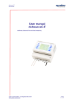
Picture 2 deltawaveC-P – With mounted ultrasonic transducers (bottom) and flow transmitters .................................. 10
Picture 3 deltawaveC-P flow transmitter ....................................................................................................................... 11
Picture 4 signal cables .................................................................................................................................................. 13
Picture 6 Spacer bar for transducer types XUC-PW-10 und XUC-PW-20..................................................................... 14
Picture 7 Transducer PW05 (500 kHZ) for large pipes – Mounting with textile belt...................................................... 15
Picture 8 Back side of deltawaveC-P with connections................................................................................................. 17
Picture 9 deltawaveC-P in the hard-shell case............................................................................................................. 19
Picture 10 Straight run requirements............................................................................................................................. 30
Picture 11 Preferable mounting positions for ultrasonic transducers (1) ....................................................................... 31
Picture 12 Preferable mounting positions for ultrasonic transducers (2) ....................................................................... 32
Picture 13 Mounting of transducers in V-mode ............................................................................................................. 33
Picture 14 Mounting of transducers in W-mode ............................................................................................................ 34
Picture 15 Mounting of transducers in Z-mode ............................................................................................................. 34
Picture 16 Mounting of ultrasonic transducers V-mode................................................................................................. 45
Picture 17 Example of the V- or W-mode without spacer bar........................................................................................ 45
Picture 18 Example of the V- or W-mode with spacer bar............................................................................................. 46
Picture 19 Example of the V-mode mount with fabric-reinforced tensioning tapes for large pipe diameters ................. 46
Picture 20 Mounting of ultrasonic transducers Z-mode ................................................................................................. 47
Picture 21 Mounting of ultrasonic transducers in Z-mode using mounting chains......................................................... 47
Picture 22 Example of Z-mode installation with fabric-reinforced tensioning tapes for large pipe diameters ................ 48
Picture 23 Layout of ultrasonic transducer .................................................................................................................... 49
Picture 24 Proper application of the acoustic gel on the sensing face of the ultrasonic transducer .............................. 49
Picture 25 Positioning the ultrasonic transducers by means of spacer bar grid ............................................................ 51
Picture 26 Securing the ultrasonic transducers (types F10 and F20) by means of stainless steel tensioning chain ..... 51
Picture 27 Attaching plastic template ............................................................................................................................ 52
Picture 28 Attaching plastic template 2 ......................................................................................................................... 52
Picture 29 Pipe with first mounting line for first transducer............................................................................................ 53
Picture 30 Measure required distance (given by flow transmitter)................................................................................. 53
Picture 31 Set up the template to mark the mounting position of the second transducer.............................................. 54
Picture 32 Auxiliary marks............................................................................................................................................. 54
Picture 33 Determining the mounting position for transducer........................................................................................ 55
Picture 34 Right mounting of transducers in Z-mode .................................................................................................... 56
Picture 35 Block diagram of heat measurement ........................................................................................................... 64
Picture 36 Mounted temperature sensor (PT100) ......................................................................................................... 65
Picture 37 Display of deltawaveC-P when connected to PC ......................................................................................... 83
Picture 38 Windows Screen .......................................................................................................................................... 83
Picture 39 Log file opened by text editor ....................................................................................................................... 84
Picture 40 Data imported into MS Excel........................................................................................................................ 85
Picture 41 Part of back side of deltawaveC-P ............................................................................................................. 104
Picture 42 Osci window send signal............................................................................................................................ 107
Picture 43 Test of transducers .................................................................................................................................... 108
Picture 44 Osci window send and receive signal ........................................................................................................ 108
Picture 45 Signal propagation ..................................................................................................................................... 112
Picture 46 Signal images ............................................................................................................................................ 113
Picture 47 Signals in Z-mode ...................................................................................................................................... 114
Picture 48 Measuring window ..................................................................................................................................... 115
Picture 49 Oscilloscope menu showing desired signals.............................................................................................. 116
Picture 50 Oscilloscope menu showing good signals.................................................................................................. 117
Picture 51 Oscilloscope menu showing noisy signal ................................................................................................... 118
Picture 52 Sharpness of signals.................................................................................................................................. 120
Picture 53 Diffuse signals............................................................................................................................................ 121
Picture 53 Interfering signals....................................................................................................................................... 123
icture 55 Separated Signals ........................................................................................................................................ 125
List of Tables
Table 1 Data in main menu (Flow1) .............................................................................................................................. 70
Table 2 Additional content of menu flow2 ..................................................................................................................... 71
Table 3 Data in menu „heat“ ......................................................................................................................................... 72
Table 4 Data in diagnostic menu 1.............................................................................................................................. 128
Table 5 Data in diagnostic menu 2.............................................................................................................................. 129
Table 6 Data in diagnostic menu 3.............................................................................................................................. 130
Table 7 List of available ultrasonic transducers .......................................................................................................... 138
systec Controls Mess- und Regeltechnik GmbH
www.systec-controls.de
4/139
V.1.13
deltawaveC-P
User manual
1.
About this manual
You don't have much time for reading? Use the beacon!
You are a:
Newcomer ?
Advanced user ?
Professional ?
The chapter headings are appended red, orange, or green spots. These will help you in getting started with
deltawaveC-P in no time at all.
Professional:
You already have professional knowledge of ultrasonic measuring systems? ->Set out with the deltawaveC-P
Getting Started (separate attachment) ->You may also want to read the chapters that are marked with the green
dot,
Advanced user:
You occasionally had the opportunity to handle ultrasonic measuring equipment?
-> Start with chapter 8.3 "Quick setup"
Start with the chapters that are marked with an orange spot. You may also want to continue reading the chapters
with the green spot.
Newcomer:
You have never worked with an ultrasonic meter before?
Start at the first chapter. You will receive a step-by-step introduction to ultrasonic measuring technology.
The fields identified with an exclamation mark contain important information that
relates to the basic data and operation of the device.
The fields identified with the letter “i” contain supplementary and helpful
information.
systec Controls Mess- und Regeltechnik GmbH
www.systec-controls.de
5/139
V.1.13
deltawaveC-P
User manual
Key aspects of deltawaveC-P:
• deltawaveC-P is a portable clamp-on ultrasonic flow meter for
measuring liquids in filled piping systems.
• deltawaveC-P operates by the ultrasonic transit-time differential
method
• Heat measurement is included as standard application. Optional
clamp-on PT100 temperature sensors are available.
• deltawaveC-P can be operated in cordless mode as well as on a
power adapter for operation with 100% duty cycle.
• The device supports measurements on piping with diameters from
DN10 to DN6000 (depending on the sensor used)
• The media to measure may have a temperature range from -40°C
to +150C (depending on the transducer used)
• You can save the measuring data to the internal SD card, read the
data via USB port, and import this data using an office software
such as MS Excel.
• The device is equipped with an electrically isolated relay output, as
well as two 4mA to 20mA current outputs that can be operated in
active and passive mode.
2. Approvals / CE
deltawaveC-P is compliant with the following European
Directives and Standards
Test specifications
DIN EN 55011 B (11/2007)
DIN EN 61000-4-2 (09/2008)
DIN EN 61000-4-3 (06/2008)
DIN EN 61000-4-4 (07/2005)
DIN EN 61000-4-5 (06/2007)
DIN EN 61000-4-6 (10/2008)
DIN EN 61000-4-8 (12/2001)
DIN EN 61000-4-11 (02/2005)
systec Controls Mess- und Regeltechnik GmbH
www.systec-controls.de
6/139
deltawaveC-P
User manual
Test requirements
DIN EN 61000-6-1 (10/2007)
DIN EN 61000-6-3 (09/2007)
systec Controls Mess- und Regeltechnik GmbH
www.systec-controls.de
7/139
deltawaveC-P
User manual
3. Measuring Principle
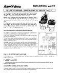
Picture 1 Measuring Principle
deltawaveC-P employs the precise ultrasonic transit-time differential
method. This method involves installation of two ultrasonic transducers on
the surface of the piping and their interconnection with the electronic
evaluation system. The ultrasonic transducers operate in alternating mode
as transmitter and receiver with cyclic exchange of ultrasonic signals.
Measurements cover the transit times of the upstream and downstream
signals (t1, t2). The electronic circuit of deltawaveC-P measures the
transit-time differential of the ultrasonic signals t1 and t2 that that travel
upstream and downstream. These signals are accelerated (t1) or retarded
(t2). The difference that develops between both signal transit times is
proportional to flow velocity and is used on combination with the piping
geometry data for precise calculation of the volumetric flow rate
(T 2 T 1)
vL
T 1 T 2 2 cos
calculation of flow velocity [m/s]
(T 2 T 1)
D2
QL
T 1 T 2 2 cos 4
calculation of flow rate [m3/s]
systec Controls Mess- und Regeltechnik GmbH
www.systec-controls.de
8/139
deltawaveC-P
User manual
The flow transmitter uses a sophisticated cross-correlation to detect
signals. This ensures a reliable detection of signals even in case of harsh
circumstances like gas and/or particle load.
systec Controls Mess- und Regeltechnik GmbH
www.systec-controls.de
9/139
deltawaveC-P
User manual
4. deltawaveC-P and components
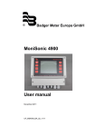
Picture 2 deltawaveC-P – With mounted ultrasonic transducers (bottom) and flow
transmitters
Your deltawaveC-P essentially consists of the ultrasonic transducers and
the flow transmitter that are mounted onto your piping.
systec Controls Mess- und Regeltechnik GmbH
www.systec-controls.de
10/139
deltawaveC-P
User manual
4.1.
deltawaveC-P flow transmitter
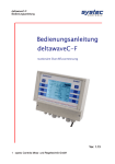
Picture 3 deltawaveC-P flow transmitter
The flow transmitter processes the signals
measurement results available to the user.
4.2.
and
makes
the
Ultrasonic transducers
The ultrasonic transducers are mounted onto the piping and transmit and
receive the ultrasonic signals that are used in the flow transmitter to
calculate the volumetric flow rate.
Ultrasonic transducer XUC-PW F21 (2 MHz), RED housing. Pipe diameters
DN10…DN100. Operating temperatures: -40°C to 150°C
systec Controls Mess- und Regeltechnik GmbH
www.systec-controls.de
11/139
deltawaveC-P
User manual
Ultrasonic transducer XUC-PW F20 (2 MHz), RED housing. Pipe diameters
DN10…DN100. Operating temperatures: -40°C to 150°C
The ultrasonic transducer XUCPW F20 is replaced by model
type XUC-PW F21
Not longer available
Ultrasonic transducer XUC-PW F10 (1 MHz), BLUE housing. Pipe
diameters: DN32 to DN400. Operating temperatures: -40 °C to 150°C
Ultrasonic transducer XUC-PW F5 (0,5 MHz), GREEN housing. For pipe
diameters from DN200 to DN6000. Operating temperatures: -40 °C to 80
°C (150 °C optional on request)
systec Controls Mess- und Regeltechnik GmbH
www.systec-controls.de
12/139
deltawaveC-P
User manual
4.3.
Mounting material and accessories
4.3.1.
Signal cables
Picture 4 signal cables
4.3.2.
Spacer bar for transducer mounting
The ultrasonic transducer models XUC-PW-F10 and XUC-PW-20 are just
used in combination with space bar “long” (40cm). Distance between two
boreholes is 15mm.
(Ultrasonic transducer XUC-PW F5 will be mounted on the pipe without
space bar by using the textile band clamps).
Space bar “long” is not compatible with
ultrasonic transducer model XUC-PW F21
400mm
Picture 5a space bar „long“ 40cm
systec Controls Mess- und Regeltechnik GmbH
www.systec-controls.de
13/139
deltawaveC-P
User manual
The ultrasonic transducer model XUC-PW-F21 is just used in combination
with space bar “short” (25cm). Distance between two boreholes is 7,5mm.
Space bar „short“ is not compatible with
ultrasonic transducer models XUC-PWF20 and XUC-PW-F10 !
Picture 5b space bar „short“ 25cm
4.3.3.
Mounting chains for transducer mounting
Picture 5 Spacer bar for transducer types XUC-PW-10 und XUC-PW-20
systec Controls Mess- und Regeltechnik GmbH
www.systec-controls.de
14/139
deltawaveC-P
User manual
Picture 6 Transducer PW05 (500 kHZ) for large pipes
– Mounting with textile belt
4.3.4.
Coupling grease
The ultrasonic coupling gel is applied between the ultrasonic
transducer and the piping in order to optimize signal input.
4.3.5.
PT100 Temperature sensors
systec Controls Mess- und Regeltechnik GmbH
www.systec-controls.de
15/139
deltawaveC-P
User manual
The clamp-on temperature sensors enable acquisition of temperature data
in heating and cooling circuits. This data is then used to calculate heating
and cooling quantities.
4.3.6.
4-20mA analogue output cable
The analog output cables can be used, for example, to connect an
external data logger or recorder to your deltawaveC-P flow transmitter
for the transmission of measured values such as flow rates, or thermal
output.
4.3.7.
cable for relay/ipulse
The relay connecting cable can be used, for example, to trigger
alerts e.g. when exceeding a certain flow rate.
.
4.3.8.
Power adapter 100-240V, 47-63Hz, 1A
systec Controls Mess- und Regeltechnik GmbH
www.systec-controls.de
16/139
deltawaveC-P
User manual
The power adapter is normally used to charge the battery. Your
deltawaveC-P, of course, supports permanent operation on mains by using
the power adapter.
4.4. Interfaces of deltawaveC-P
1
2a
2
USB
Reset
3
4
5
Down
Up
Relais/Impulse
6
T1/T2
7
Analog Out
Power
18,5 VDC
deltawaveC-P
Picture 7 Back side of deltawaveC-P with connections
1
Power Input
This jack is used to connect the plug-in power adapter that is included with
your deltawaveC-P package
2
USB Interface (Mini.USB Typ B)
Enable access to the integrated SD memory card from a PC. This card is
used to store process tag data and measurement data (LOG files).
Windows XP or later versions detect the internal SD Card as mass
storage medium. This means that you do not need to install additional
drivers..
systec Controls Mess- und Regeltechnik GmbH
www.systec-controls.de
17/139
deltawaveC-P
User manual
2a
Hardware Reset
Please use a small screw driver (or paper clip) to press the reset button.
You can find additional information about using the reset in chapter 12.8.
3
BNC Inputs for ultrasonic transducers
Jacks for the ultrasonic transducers.
4
Relay output/Impulse output (4-Pol Mini DIN)
Electrically isolated output with NO (normally open) contact.This internal
NO contact is open unless an actuating signal is generated. This means
that you can assign alarm or threshold limit functions to this output.
Impulse output with open collector, passive.
5
Inputs for temperature sennsors PT100 (6-Pole Mini DIN)
Receptacles for the optional temperature sensors that enable the
use of the internal heat measurement function of your
deltawaveC-P.
6
4-20mA Analogue outputs (5-Pol Mini DIN)
These outputs can be assigned variables such as the flow rate and return a
current that is proportional to the value of the variables. The outputs
operate in active (power provided by flow transmitter) 2-wire mode.
systec Controls Mess- und Regeltechnik GmbH
www.systec-controls.de
18/139
deltawaveC-P
User manual
deltawaveC-P provides a Hardware Reset function that
resets the device to a defined initialized state. You trigger a
Hardware Reset by actuating the pushbutton switch through
the Reset opening on the deltawave, for example, using a
paper clip.
4.5.
Scope of supply basis package
Picture 8 deltawaveC-P in the hard-shell case
•
Hard-shell case
systec Controls Mess- und Regeltechnik GmbH
www.systec-controls.de
19/139
deltawaveC-P
User manual
•
•
•
•
•
•
•
•
•
•
•
deltawaveC-P flow transmitter
Plug-in power adapter, including an IEC appliance power cable
Signal cable
Ultrasonic transducer (as ordered by the customer)
Spacer bar for the ultrasonic transducers
Cable for the 4 mA to 20 mA analog output (Mini DIN, alligator
clips)
Digital output cable for the relay output, Impulse output (Mini DIN,
alligator clips)
Stainless steel mounting chains (up to DN400)
Getting Started ("Quick-start") manual
CD with operating instructions
Ultrasonic coupling grease
Other ultrasonic transducers for smaller or larger pipe dimensions, as well
as clamp-on temperature sensors, are available on separate order. You
can reach your personal contact partner on the Internet at
www.systec-controls.de, or at the phone number +49 (0)89 80 90 60.
4.6. Saftey instructions
•
•
•
•
•
The flow transmitter may not be operated outside the temperature
range from -20°C to 60°C!
The ultrasonic transducers are sensitive to mechanical stress such as
impact and vibration. You should always safeguard the transducers
against strong vibration or impact. Irreparable damage or destruction
must be expected if you unintentionally drop the transducer!
The plug-in power supply is suitable for operation in closed rooms only!
The plug-in power adapter or the 230 V IEC power cable must be
replaced completely in the case of mechanical or electrical damage!
Information on operation in ATEX protected zones: The flow transmitter
is generally not approved for operation in Ex / ATEX protection zones!
The standard ultrasonic transducers are not approved for operation in
Ex protection zones!
Optional ultrasonic transducers for operation in ATEX protection
zones are expected to be available towards the mid of 2012.
The ultrasonic transducers may not be operated outside their specified
media temperatures.
systec Controls Mess- und Regeltechnik GmbH
www.systec-controls.de
20/139
deltawaveC-P
User manual
5. Operating
5.1. Control Buttons
2
1
3
switches the device On and Off. To shut down the device, press the
button for a duration of approx. 3 seconds and then release it.
1
2
3
switches the backlight On and Off
Multifunctional buttons: Use this button to select the function that is
displayed next to it on the screen
.
systec Controls Mess- und Regeltechnik GmbH
www.systec-controls.de
21/139
deltawaveC-P
User manual
5.2. How to navigate
Use the corresponding multifunctional buttons:
Arrow buttons for navigation
Confirms your entry
Confirms your entries and opens the next window
Returns you to the previous window
Increases the value
Reduces the value
XYZ
Triggers the XYZ function (variable, depending on the application
No function
systec Controls Mess- und Regeltechnik GmbH
www.systec-controls.de
22/139
deltawaveC-P
User manual
6. Get started
6.1. Basic settings, main menu, navigation
6.1.1.
Setting language
Switch on the device. During the start sequence, press the
multifunctional button that is located next to the "SETUP" field.
Confirm the "SETUP LANG." button
systec Controls Mess- und Regeltechnik GmbH
www.systec-controls.de
23/139
deltawaveC-P
User manual
Use the arrows in the next window to select the dialog language.
Confirm your entry with "Enter". Exit the menu with "SETUP
The language setting changes the language used in the menus.
The language in the fields next to the multifunctional button
remains more or less unchanged
6.1.2.
Navigation in main menu (flow 1)
The "Flow rate 1" measuring window is automatically opened with a delay
of a few seconds after power on of the deltawaveC-P and display of the
start screen. The "Flow 1" measuring window provides an overview of all
data that is necessary for flow and heat measurements.
Select "Setup“
systec Controls Mess- und Regeltechnik GmbH
www.systec-controls.de
24/139
deltawaveC-P
User manual
Select "COMPL Setup" once you can see the window“
You are now in the main menu. You can select all necessary
functions of the device in this menu.
To return to the measuring window, proceed as follows: Select
"ESC" -> "MEAS" in the next window
You have now learned the fundamentals for operating your deltawaveC-P .
You can accelerate access to the main menu after power on
by way of a simple trick: select the start sequence "SETUP"
directly after power on of the deltawaveC-P . Select "KOMPL
SETUP" in the next window
systec Controls Mess- und Regeltechnik GmbH
www.systec-controls.de
25/139
deltawaveC-P
User manual
6.1.3.
Setting the time and date
Once you selected the dialog language, the setup menu of the device will
be opened
Select the “System Setup” menu command using the arrow keys.
Select the Time and Date menu command
Enter the time in the following notation Hour (hh) : Minute (mm) : Second
(ss). Enter the date in the following notation Day (dd) : Month (mm) : Year
(YYYY).
systec Controls Mess- und Regeltechnik GmbH
www.systec-controls.de
26/139
deltawaveC-P
User manual
6.1.4.
The status bar
The status bar is located in the uppermost row of the display.
Time: Displays the current time. This is also the system time. A time stamp
that is derived from the system time will be applied to the measurement
data you subsequently log.
SD memory: Displays the free space on the internal SD memory card of
the device (standard is 2 GB).
Backup battery: Provides information about the status of the rechargeable
battery, e.g.:
•
Load: The device is powered using the power adapter while the
battery is charged. The empty battery needs a charging time of
approx. 5 hours
•
Full: The battery is in charged state. The device any be operated
for a time of approx. five hours when the display backlight is
switched off and for approx. three hours when it is switched on.
Percentage display: Displays the charging state of the battery
systec Controls Mess- und Regeltechnik GmbH
www.systec-controls.de
27/139
deltawaveC-P
User manual
The times specified apply to a new battery. The factual
operating/load cycles may deviate from the specified time values
systec Controls Mess- und Regeltechnik GmbH
www.systec-controls.de
28/139
deltawaveC-P
User manual
7. Preparing for measurement
The following section elaborates on essential aspects that must be taken
into account for successful flow rate measurements.
7.1. Required straight runs
The selection of the mounting location has a significant impact on
measurement quality. Particularly the charge and discharge area listed in
the following table should be taken into account
systec Controls Mess- und Regeltechnik GmbH
www.systec-controls.de
29/139
deltawaveC-P
User manual
Picture 9 Straight run requirements
systec Controls Mess- und Regeltechnik GmbH
www.systec-controls.de
30/139
deltawaveC-P
User manual
7.2. Mounting positions for transducers
7.2.1.
Basics on the mounting of ultrasonic transducers
The pipe always has to be filled completely at the
mounting positions of the ultrasonic transducers! It is
not possible to take measurements on partially filled
piping
The ultrasonic transducer can be operated in any mounting position.
However, conformation with the mounting positions shown below is
mandatory: The drawing shows the side view of the piping
7.2.2.
Mounting ultrasonic transducers on horizontal piping
Picture 10 Preferable mounting positions for ultrasonic transducers (1)
On horizontal piping, it is recommended to mount the transducer with an
offset of approx. +/-45% to the horizontal plane. This is based on the fact
that there is a risk of the accumulation of bubbles in the upper section and
sedimentation in the lower section of the pipe.
systec Controls Mess- und Regeltechnik GmbH
www.systec-controls.de
31/139
deltawaveC-P
User manual
Picture 11 Preferable mounting positions for ultrasonic transducers (2)
deltawaveC-P uses the cross section of the pipe to calculate the flow. The
cross section is calculated from the parameterized inner diameter (user
setting). If you have sedimentation in your pipe which decreases the real
inner diameter you might get a (usually very small) uncertainty. Same
happens when inner diameter is not known / estimated.
(T 2 T 1)
D2
QL
T 1 T 2 2 cos 4
If you usually want to measure pipes with unknown /
undocumented wall thicknesses we would recommend to use a
wall thickness gauge to precesily measure the wall thickness.
systec is offering the wall thickness gauge deltawaveC-P-WD.
Please ask you systec dealer for further information or visit us at
www.systec-controls.de
systec Controls Mess- und Regeltechnik GmbH
www.systec-controls.de
32/139
deltawaveC-P
User manual
7.2.3.
Ultrasonic transducers on non-planar surface
You should never mount the transducers on non-planar surfaces such as
welding seams or deformations. You should always try to remove thick and
uneven protective paint coating from the piping area where the ultrasonic
transducers are to be mounted
7.3.
Mounting ultrasonic transducers
This chapter informs you of the options for mounting the ultrasonic
transducers. The V-mode is standard for most applications.
7.3.1.
V-Mode
Transducer 1
Transducer 2
Picture 12 Mounting of transducers in V-mode
In the so-called V-mode, both ultrasonic transducers are mounted onto the
same side of the pipe. This mode is the standard for small and medium
pipe dimensions. The ultrasonic signals are reflected from the pipe wall.
systec Controls Mess- und Regeltechnik GmbH
www.systec-controls.de
33/139
deltawaveC-P
User manual
7.3.2.
W- Mode
Transducer 1
Transducer 2
Picture 13 Mounting of transducers in W-mode
The W-mode is a special method for mounting the ultrasonic transducers.
This method is usually employed on small to very small piping.
7.3.3.
Z- Mode
Transducer 1
Transducer 2
Picture 14 Mounting of transducers in Z-mode
The Z-mode is a special method for mounting the ultrasonic transducers. In
comparison to the V- and W-mode, the signal is transmitted across a
shorter distance with this installation method. It is normally used for
systec Controls Mess- und Regeltechnik GmbH
www.systec-controls.de
34/139
deltawaveC-P
User manual
measurements in large-scale piping systems, or where the system is filled
with heavily contaminated or gas-loaded media.
8. Measuring with deltawaveC-P
In 5 steps to flow measurement:
Look for a suitable location for mounting the ultrasonic
transducers
Parameterize your deltawaveC-P
Mount the ultrasonic transducers onto the piping
Perform a zero calibration
Start the flow measurement
systec Controls Mess- und Regeltechnik GmbH
www.systec-controls.de
35/139
deltawaveC-P
User manual
8.1. Parameterization
8.1.1.
Fundamentals of parameterization
The Parameterization chapter defines the input of all data that is necessary
for flow measurement.
"QUICK SETUP": The Quick Setup guide offers step-by-step
instructions on the essential tasks you have to complete for
deltawaveC-P parameterization. This Quick Setup is quite sufficient for
handling most applications and gets you started with fast and efficient
parameterization in no time at all.
"CMPL SETUP": The complete setup function enables access to
all options and expert settings.
8.2. What needs to be parameterized?
The pipe's outer diameter or circumference.
The wall thickness of the pipe. The material and thickness of the
pipe lining, if such lining exists.
The pipe material
The medium
The type of ultrasonic transducers
The mounting mode for the ultrasonic transducers
Ultrasonic measurement is based on the signal transit time
process. The ultrasonic signals penetrate the piping and the
medium. In order to calculate the signal transit time, each
medium, piping material and existing lining will be assigned a
sonic speed value, as well as the pipe diameter or
circumference value. The tabular database of deltawaveC-P
systec Controls Mess- und Regeltechnik GmbH
www.systec-controls.de
36/139
deltawaveC-P
User manual
specifies the sonic speed values for the materials and media.
The sonic speed for materials not listed in the tables has to be
entered manually. Tables that list additional sonic speed
parameters for different materials are available in the annex to
these operating instruction
systec Controls Mess- und Regeltechnik GmbH
www.systec-controls.de
37/139
deltawaveC-P
User manual
8.3. Parameterizing with Quick Setup
How to access the parameterization dialog:
After power on: Select "Setup" -> "Quick Setup" within the start sequence.
In the primary measuring window "Flow 1": Select "Setup" -> "Quick
"Setup".
Start
1
Specify whether to enter the pipe circumference or
outer diameter
OR
Enter the outer diameter
systec Controls Mess- und Regeltechnik GmbH
www.systec-controls.de
Enter the diameter
38/139
deltawaveC-P
User manual
Enter the pipe's wall thickness:
2
It is advisable to use a wall thickness meter if you do
not know this parameter.
3
Choose pipe material:
OR
systec Controls Mess- und Regeltechnik GmbH
www.systec-controls.de
39/139
deltawaveC-P
User manual
4
Does the pipe have a lining YES/NO?
5
NO
OR
Enter the thickness |
of the lining
YES
Select the database, or
user input if a material is
not listed in the database
systec Controls Mess- und Regeltechnik GmbH
www.systec-controls.de
40/139
deltawaveC-P
User manual
OR
Choose lining material
fom data base
Enter speed of sound
of user-defined coating
Rohrauskleidung
5
Select the medium:
OR
systec Controls Mess- und Regeltechnik GmbH
www.systec-controls.de
41/139
deltawaveC-P
User manual
Enter the
kinematic viscosity of
the medium:
Enter the thermal i
capacity of the medium
Enter the density of
the medium:
systec Controls Mess- und Regeltechnik GmbH
www.systec-controls.de
42/139
deltawaveC-P
User manual
6
Select a suitable ultrasonic transducer
For information on suitable transducers for specific
pipe dimensions, refer to chapter "deltawaveC-P and
components “.
7
Select a suitable mounting mode
For information on suitable transducers for specific
pipe dimensions, refer to chapter "deltawaveC-P and
components .
systec Controls Mess- und Regeltechnik GmbH
www.systec-controls.de
43/139
deltawaveC-P
User manual
8
Output of the distance between
the ultrasonic transducers:
Before you start
measuring we
highly
recommend a
zero setup. How
to perform a
correct zero setup
is written in
chapter 8.6.
Attention
Please pay attention which space bar type is displayed.
Long= distance between two boreholes is 15mm.
Short= distance between two boreholes is 7,5mm.
The space bar type “short” can only be used in combination with
ultrasonic transducer type XUC-PW-F21
The space bar type “long” can only be used in combination with
ultrasonic transducers type XUC-PW-F20 and XUC-PW-F10.
END
The distance between transducers is specified in millimeters
and always measured between the faces of transducers 1
and 2. These dimensions are independent of the selected
mounting mode.
systec Controls Mess- und Regeltechnik GmbH
www.systec-controls.de
44/139
deltawaveC-P
User manual
8.4. Mounting distance
The distance between the ultrasonic transducers is always measured
between their opposing surfaces in all mounting modes. Once you have
completed the parameterization of the measuring point, the flow transmitter
displays the distances that have to be set up using a measuring tape.
When using a spacer bar in the so-called V-mode, you can position the
transducers conveniently by means of the spacer bar.
8.4.1.
V-mode and W-mode
Mounting
distance
Picture 15 Mounting of ultrasonic transducers V-mode
Picture 16 Example of the V- or W-mode without spacer bar
systec Controls Mess- und Regeltechnik GmbH
www.systec-controls.de
45/139
deltawaveC-P
User manual
Picture 17 Example of the V- or W-mode with spacer bar
Picture 18 Example of the V-mode mount with fabric-reinforced tensioning tapes for
large pipe diameters
systec Controls Mess- und Regeltechnik GmbH
www.systec-controls.de
46/139
deltawaveC-P
User manual
8.4.2.
Installation at Z- Mode
Distance
Transducer 1
Abstand 2
Transducer
Picture 19 Mounting of ultrasonic transducers Z-mode
Picture 20 Mounting of ultrasonic transducers in Z-mode using mounting chains
systec Controls Mess- und Regeltechnik GmbH
www.systec-controls.de
47/139
deltawaveC-P
User manual
Picture 21 Example of Z-mode installation with fabric-reinforced tensioning tapes for
large pipe diameters
8.4.3.
Introduction in ultrasonic transducer mounting
Basic structure of the ultrasonic transducer:
The ultrasonic transducer (F10 and F20) consists of a transducer carrying
element and the actual ultrasonic transducer. The ultrasonic transducer is
made of plastic (PEEK) that has a beige colour and is protected by means
of a metal sheath. The transducer is secured by means of a knurled screw
that is passed through the transducer support. This support can be shifted
in axial direction (blue arrow) with the help of the knurled screw (A).
The ultrasonic transducer type F05 consists only of the sensor sheath and
the actual ultrasonic transducer.
Sheath
Ultrasonic transducer
systec Controls Mess- und Regeltechnik GmbH
www.systec-controls.de
48/139
deltawaveC-P
User manual
Knurled screw (A)
Transducer face
Transducer support
Picture 22 Layout of ultrasonic transducer
Before you mount the ultrasonic transducer onto the piping, the beige
transducer surface has to be brought into the position underneath the
bottom edge of the transducer support (“srew transducer into support)
Picture 23 Proper application of the acoustic gel on the sensing face of the
ultrasonic transducer
systec Controls Mess- und Regeltechnik GmbH
www.systec-controls.de
49/139
deltawaveC-P
User manual
8.4.4. Mounting in V-mode or W-mode
Once you have completed parameterization of the measuring point the flow
transmitter displays the distance between the transducers in mm (face to
face, see Picture 22) units and as number of grid holes for use of the spacer
bar (ultrasonic transducers type F10 and F20). Grid number 5, for example,
is equivalent to the number of grid holes between the ultrasonic
transducers, plus the position at which the knurled screw of the
opposing transducer has to be mounted. Install the transducers on the
spacer bar as shown in the figure. Secure the transducers on the spacer
bar using the knurled screws (B).
Knurled screw (B)
1 2
3 4 5 Example: Grid number 5
If the wrong space bar (short or long) is applied, the measurement
fails or the measurement will have wrong values.
systec Controls Mess- und Regeltechnik GmbH
www.systec-controls.de
50/139
deltawaveC-P
User manual
Picture 24 Positioning the ultrasonic transducers by means of spacer bar grid
8.4.5. Fix transducers at pipe using mounting chains
Knurled screw (A)
Picture 25 Securing the ultrasonic transducers (types F10 and F20) by means of
stainless steel tensioning chain
Fix the ultrasonic transducers using the stainless steel chains (with or
without spacer bar).
Attach the chains to the hooks on the transducers while keeping them
under (only slightly!) tension. Approach the ultrasonic transducers to the
pipe by adjusting the knurled screw (A) until the transducer is pressed
slightly onto the pipe.
systec Controls Mess- und Regeltechnik GmbH
www.systec-controls.de
51/139
deltawaveC-P
User manual
8.4.6.
Mounting the ultrasonic transducers based on the Z method
Use a plastic or paper template to mark the mounting positions. The
example shows how to mark the positions using a plastic template.
Wrap the plastic template once around the pipe at the mounting
position of the first ultrasonic transducer (transducers face has to
be in line with the line to be drawn).
Using a felt tip pen, draw a line on the pipe along the template
(corresponds with the pipe circumference)
Picture 26 Attaching plastic template
Draw line
Picture 27 Attaching plastic template 2
systec Controls Mess- und Regeltechnik GmbH
www.systec-controls.de
52/139
deltawaveC-P
User manual
Picture 28 Pipe with first mounting line for first transducer
On successful completion of parameterization, your deltawaveC-P
displays the axial distance between the ultrasonic transducers
(transducer distance). Measure the transducer distance based on
the value displayed on your deltawaveC-P , starting from the first
line drawn to the position at which the second line is to be drawn
(mounting position for face of the second transducer).
Picture 29 Measure required distance (given by flow transmitter)
systec Controls Mess- und Regeltechnik GmbH
www.systec-controls.de
53/139
deltawaveC-P
User manual
Picture 30 Set up the template to mark the mounting position of the second
transducer
Draw two crosshairs on the same axis, centered on the lines drawn
with the help of the template..
2
1
Picture 31 Auxiliary marks
systec Controls Mess- und Regeltechnik GmbH
www.systec-controls.de
54/139
deltawaveC-P
User manual
Mount the first transducer. Its face is positioned on the axis of the
first line drawn. The transducer face (not the transducer) is
centered onto the first crosshair. Now, calculate half of the pipe's
outer circumference..
U1 2
2 r
2
r = Radius of pipe including wall thickness („outer radius“)
Example: Radius (outer) = 250mm -> U = 2*3.1415*250mm / 2 = 785.4mm
Position the zero line of the measuring tape onto the center of the
second crosshair drawn on the pipe (at same level as first
transducer). Measure the previously calculated distance (half
circumference). You should now have located the precise position
opposite to the first transducer. Draw a (third) onto the pip at this
position.
Picture 32 Determining the mounting position for transducer
Mount the second transducer. Its face is positioned on the axis of
the second line drawn. The transducer face is centered onto the
third crosshair. The transducers are now mounted precisely
opposite to each other and are prepared for measuring in Z-mode.
systec Controls Mess- und Regeltechnik GmbH
www.systec-controls.de
55/139
deltawaveC-P
User manual
Picture 33 Right mounting of transducers in Z-mode
8.5. Edit parameters
You can also parameterize the system using the complete setup menu.
However, this method is less convenient, as it does not offer a step-by-step
guide to parameterization. It is therefore recommended to use the main
menu only in situations that require editing of an individual parameter.
You have direct access to the parameters of the piping and medium, as
well as to the dialogs for selecting the ultrasonic transducers and mounting
mode.
If you only want to change the mounting mode from V to Z, simply select
"Transducer parameters" and change it without having to run a complete
"Quick Setup" session.
This document provides only a brief overview of parameterization and main
menu in the form of structure diagrams that help you to identify the
functions grouped in the respective menu. The basic parameterization
sequence is similar to a complete parameterization using the Quick Setup
tool. We therefore do not elaborate in closer detail on this topic.
Navigate to the main menu:
In the primary measuring window "Flow 1": Select "Setup" -> "CMPL.
SETUP"
systec Controls Mess- und Regeltechnik GmbH
www.systec-controls.de
56/139
deltawaveC-P
User manual
Select the parameters to edit, e.g. "Pipe parameters", "Medium
parameters", or "Transducer parameters":
systec Controls Mess- und Regeltechnik GmbH
www.systec-controls.de
57/139
deltawaveC-P
User manual
Direct access to the pipe parameters:
Pipe Setup
Outer diameter
or
Enter
Outer diameter
Outer Circumference
Enter
Outer Circumference
Enter wall thickness
or
Pipe material
from data base
Select from data base:
1 Steel
2 Stainless Steel…..
User defined
pipe material
Enter speed of sound of
your pipe material pipe
material
Does pipe have internal coating?
or
YES
NO
Enter thickness of
coating
Material of coating
Choose from
data base
Select:
1 Rubber
2…
or
Enter
customized
coating
Enter speed of
sound of your
coating
END
systec Controls Mess- und Regeltechnik GmbH
www.systec-controls.de
58/139
deltawaveC-P
User manual
Setup fluid data
Fluid Setup
Choose from data base
or
Select from data base:
1 Water 20 Degree
2…
Set user-defined fluid
Set speed of sound of
user-defined fluid
Enter kinematic viscosity
Enter heat capacity
Enter density
END
Direct access to selection of ultrasonic transducer and mounting mode:
Transducer Setup
Choose transducer
Choose mounting mode
END
systec Controls Mess- und Regeltechnik GmbH
www.systec-controls.de
59/139
deltawaveC-P
User manual
8.6. Zero Setting
It is advisable to run a zero calibration before you start measurements if
possible.
Prerequisite for error-free zero calibration is the complete
parameterization of the device, proper installation of both
ultrasonic transducers on the pipe, as well as their
electrical interconnection with the flow transmitter. Also
there should be really “zero-flow”. It is recommendable to
wait some minutes after stopping process / shut-off pipe to
allow the flow to calm down.
8.6.1.
Zero calibration starting in "Flow1” menu
Close the valves of the piping.
Navigate to the "Setup" window as follows, using either of
three options:
- After power on: Select "Setup" within the start sequence
- In the primary measuring window "Flow 1": Select "Setup" and
“Zero Setup”
- Select "Set Zero"
The following window opens on completion of zero calibration:
systec Controls Mess- und Regeltechnik GmbH
www.systec-controls.de
60/139
deltawaveC-P
User manual
Your deltawaveC-P displays the calculated correction value for the signal
transit time on completion of zero calibration:
8.6.2.
Zero calibration using the main menu:
In the main menu, select "damping/cutOff/Zero" -> "Zero calibration“
Stop flow of media (closing a valve)
Select Set Zero
systec Controls Mess- und Regeltechnik GmbH
www.systec-controls.de
61/139
deltawaveC-P
User manual
8.6.3.
Deleting the zero value
In the main menu, select "Zero Setup" - "Zero" - "Delete zero". This action
deletes your zero calibration and resets the device to factory settings
.
Once the zero offset has been set it will remain in the
system until it will be deleted or a new zero offset will have
been set. Please consider this for your next item. We
recommend to make new zero setting at each new
measurement when possible.
In the course of zero calibration with closed pipe valves, your
deltawaveC-P calculates the transit-time differential that may
develop between the transducers and any residual flow. This
calculated time (including zero) is automatically included for
subsequent calculations during flow measurement. This method
enhances the precision of your flow measurements. If it is not
possible close the pipe valves, delete the zero value that may
have been set previously. If anything prevents you from
performing a zero calibration, you will have to take the
corresponding imprecision into account in your measurements.
The zero setpoint is retained in device memory until it is
overwritten with a new zero setpoint. If it was possible to close
the pipe valves, check the "Flow" column in one of the three
measuring window to determine whether or not the flow rate is
going down. You should not perform a zero calibration until a
settled value is output to the flow display. A stop valve is not
available at all positions of the piping. The tolerances that
develop during installation, including tolerances of the ultrasonic
transducers and pipe data, will lead to a certain zero offset error
in the measuring equipment. Provided meticulous care was
taken during installation, the flow velocity error should stay
within the range from 0.00 m/s to 0.03 m/s. The zero offset error
is reduced in proportion with increasing pipe size.
systec Controls Mess- und Regeltechnik GmbH
www.systec-controls.de
62/139
deltawaveC-P
User manual
8.7. Heat measurement
The integrated heat measurement function enables you to determine the
heat and cooling flow in your application using PT100 temperature sensors.
8.7.1.
Introduction
The PT100 no. 2 is installed in the warmer, while PT100 no. 1 is installed
on the cooler section of the circuit (The PT100 are numbered on the cable).
You can position the ultrasonic transducers at the warmer or colder section.
However, you are well advised to install the transducers in the cooler
section, as it is unlikely that they will be operated beyond their permissible
temperature limit in these sections.
deltawaveC-P displays the thermal output and the accumulated heat
quantity
systec Controls Mess- und Regeltechnik GmbH
www.systec-controls.de
63/139
deltawaveC-P
User manual
PT100 Nr. 2
PT100 Nr. 1
Picture 34 Block diagram of heat measurement
deltawaveC-P shows heat (kWh) and thermal output (kW)
Calculating thermal output
The cross-sectional area of the pipe's inner diameter [A] is multiplied by the
flow velocity [v] and specific thermal capacity of the medium [c], as well as
the differential temperature of both PT100, [T_hot- T_cold]. The product
defines thermal output [Q] in W units.
Q A v cw (Theiß Tkalt )
Q [W , kW ]
systec Controls Mess- und Regeltechnik GmbH
www.systec-controls.de
64/139
deltawaveC-P
User manual
Calculating heat (quantity)
The heat quantity is derived as a function of thermal output over time.
Q [ J , kW / h]
Q Q dt
8.7.2.
Installing the PT100
The PT100 temperature sensors can be mounted on your piping using a
metal strap (photo), mounting chains, or a fabric-reinforced tape strap
(which is standard when buying deltawaveC-P package). Install the PT100
on the pipe as follows, for example:
Picture 35 Mounted temperature sensor (PT100)
The measuring method deployed for the PT100 is a relative
measurement. This means that the measured temperature values
with absolute reference may deviate from this measuring
equipment (e.g. compared to submersion thermometers). It is of
importance to set up a relation between both PT100s. The ideal
differential temperature between the PT100 temperature sensors
should amount to zero degrees prior to installation on the piping
systec Controls Mess- und Regeltechnik GmbH
www.systec-controls.de
65/139
deltawaveC-P
User manual
8.7.3.
Zero setup of temperature sensors
From main menu flow1: Press button SETUP -> COMPL SETUP ->
CALIBRATION SETUP -> Select „PT100 T2-T1“
The differential temperature between both PT100 should amount
to approximately zero degrees prior to installation of the
transducers on the piping. You should avoid touching the
transducers in the preliminary phases. To equal both PT100s you
can e.g. put them in a glass of water for a couple of minutes. o
check the temperature of both transducers, use the values
displayed in the "Heat quantity" measuring window that is
described in the following chapte.
Select “READ OFFSET". Now, deltawaveC-P automatically calculates the
T2 to T1 offset. On completion of this calculation, the differential
temperature T1 to T2 should amount to approximately zero degrees. Use
the "Reset Offset" command to reset the calculated differential temperature
to zero
systec Controls Mess- und Regeltechnik GmbH
www.systec-controls.de
66/139
deltawaveC-P
User manual
8.7.4. Absolute thermal output measurements (absolute measurement)
with PT100
The device supports the alignment of the displayed temperature with a
reference thermometer for each PT100 used. This functionality can be
useful, for example, for heat measurements.
Example: The resistance thermometer installed in the pipe displays
80 °C. However, the resistive contact thermocouple PT100 T1 of
your deltawaveC-P displays only 78.5 °C. deltawaveC-P also
supports manual adjustment of the offset. In this case, specify a
setpoint of 80 °C. The setpoint is an absolute value and not an
offset.
Proceed as follows:
In the primary measuring window "Flow 1": Select "SETUP" -> "CMPL
SETUP" -> CALIBRATION SETUP -> "PT100 T1"
Enter the absolute setpoint for T1. Caution: The setpoint is an absolute
value and not an offset in terms of the temperature displayed! You can
select "RESET" to delete the setpoint for PT100 T1. In this case, PT100 will
indicate the actual temperature
systec Controls Mess- und Regeltechnik GmbH
www.systec-controls.de
67/139
deltawaveC-P
User manual
Same procedure is applicable for second temperature sensor. In this case
please choose PT100 T2 in calibration menu.
systec Controls Mess- und Regeltechnik GmbH
www.systec-controls.de
68/139
deltawaveC-P
User manual
9. Measuring windows of deltawaveC-P
9.1. The main display „flow1“
The flow1 menu is the main menu which shows the current measured
values like flow, thermal output etc.
How to open the central measuring window "Flow 1“
After power on: Wait approx. five seconds for the display of the start
screen. The deltawaveC-P automatically opens the central measuring
window "Flow 1“.
Starting in the main menu: Select "ESC" > "MEAS.“
The Flow 1 measuring window provides concise information that is
important for your flow and heat
Parameter
Designation
Displays the current flow rate
Totalizer = flow rate counter. Displays the actual flow
rate value. Displays the actual heat quantity
systec Controls Mess- und Regeltechnik GmbH
www.systec-controls.de
69/139
deltawaveC-P
User manual
Displays the actual heat quantity
Displays the actual heat quantity
Returns the sonic speed of the mediums
Specifies the signal quality in [%]
Outputs the actual temperature of the connected
PT100 temperature sensors. Signals the
measurement status
Signalisiert den Status der Messung
LOG
INACTIVE
LOG ACTIVE
USB ON
Indicates deactivated data logging
Indicates ongoing data logging
Indicates USB-connection to PC
Table 1 Data in main menu (Flow1)
Resets the Totalizer (flow rate counter) to zero
Change to the diagnostics windows. Only necessary for information or if
you do not receive any measurement results
Change to measuring window "Flow 2“ providing further information
Change to oscilloscope menu where you can watch signals
systec Controls Mess- und Regeltechnik GmbH
www.systec-controls.de
70/139
deltawaveC-P
User manual
9.2. Measuring window "Flow 2“
How to open the central measuring window "Flow 2"
Starting in the primary measuring window "Flow 1": Select "Flow 2"
Flow measuring window 2 provides concise information that is important for
your flow measurements (without heat measurement). The window also
provides additional flow velocity data.
Funktion:
Designation
Displays the actual flow velocity
Table 2 Additional content of menu flow2
Change to the primary measuring window“
"Flow 1". Change to measuring window "Heat“
9.3. Measuring window "Heat“
How to open the primary measuring window "Heat”
systec Controls Mess- und Regeltechnik GmbH
www.systec-controls.de
71/139
deltawaveC-P
User manual
Starting in the primary measuring window "Flow 1:Select "Flow 2"
-> Heat"
The "Heat" measuring window outputs concise information that is important
for your heat measurements
Parameter:
Designation
Displays the actual thermal output.
Displays the actual heat quantity.
Displays the differential temperature between the
connected PT100 T1 and PT100 T2 temperature
sensors
Table 3 Data in menu „heat“
Change to measuring window "Flow 2“
9.4. Selecting the physical units
How to access the "Units Setup" menu:
In the primary measuring window "Flow 1": Select "SETUP" -> "CMPL
SETUP" -> Navigate to "Units Setup" in the main menu.
Select the variable at which you want to change the physical unit:
systec Controls Mess- und Regeltechnik GmbH
www.systec-controls.de
72/139
deltawaveC-P
User manual
9.4.1.
Selecting the flow unit
How to access the physical unit from submenu "Flow1"
In the primary measuring window "Flow 1": Select "SETUP" -> "CMPL
SETUP" -> Navigate to "Units Setup" in the main menu and then select
"Flow"
Select the parameter you want to change the unit:
systec Controls Mess- und Regeltechnik GmbH
www.systec-controls.de
73/139
deltawaveC-P
User manual
Now select the desired unit
The physical unit gallon is a metric unit
9.5.
Selecting the physical unit for the totalizer
How to access the physical unit submenu "Totalizer"
In the primary measuring window "Flow 1": Select "SETUP" -> "CMPL
SETUP" -> Navigate to "Units Setup" in the main menu and then select
"Total Flow"
Select the physical unit:
systec Controls Mess- und Regeltechnik GmbH
www.systec-controls.de
74/139
deltawaveC-P
User manual
The physical unit gallon is a metric unit
9.5.1.
Selecting the physical unit for thermal output
How to access the physical unit submenu "Thermal output"
In the primary measuring window "Flow 1": Select "SETUP" ->"CMPL
SETUP”. In the main menu, select "Units Setup"-> "Power"
Select the physical unit:
9.5.2.
Selecting the physical unit for heat quantity
How to access the physical unit submenu "Heat quantity"
In the primary measuring window "Flow 1": Select "SETUP" -> "CMPL
SETUP" — In the main menu, select "Units Setup" -> "Heat"
Select the physical unit:
systec Controls Mess- und Regeltechnik GmbH
www.systec-controls.de
75/139
deltawaveC-P
User manual
9.6. Saving, loading and managing data
9.6.1.
Logging data
The term data logging denotes the recording (saving) of measured value
data on the internal SD Memory Card. All measurement data like
time&date, flow, velocity, totalizer and thermal output, heat quantity and
temperatures (when using temperature sensors). If temperature sensors
should not be in use these values are shown as “0” in the log files. The
data is stored in a text file (*.txt) which allows easy and quick export into
office software like Microsoft Excel or similar.
9.6.2.
Time controlled data logging
Your deltawaveC-P supports time controlled data logging to the internal
SD memory card.
systec Controls Mess- und Regeltechnik GmbH
www.systec-controls.de
76/139
deltawaveC-P
User manual
Please note that the time controlled data logging uses the
internal system time which needs to be set by user. If you
use current time at data logger when having completely
different system time data logger might not be activated!
In the primary measuring window "Flow 1": Select "SETUP" -> "CMPL
SETUP" -> "Data logger"
You can now edit the log files, or parameterize the data logger. Navigate to
the Data logger parameters field and confirm your entry with "NEXT“.
Navigate to the Data logger parameters field and confirm your entry with
"NEXT". Assign a file name (min. 4 characters). Use the arrow keys to
select the letters, or delete a letter by means of "DEL". Accept the letter
with "ENTER". Select "DONE" and press "ENTER" to conclude data input.
systec Controls Mess- und Regeltechnik GmbH
www.systec-controls.de
77/139
deltawaveC-P
User manual
Continuous data logging:
Example: You want to log the data generated from May 25, 20YY, 3:00 PM
to May 26, 20XX, 4:00 PM. The data is to logged at cyclic intervals of 60
seconds to the SD Card^
Start 15:00
25.05.20YY
27.05.20YY
Stop 16:00
26.05.20YY
Enter the start date May 25, 20XX
Enter the start time 3:00 PM
Enter the duration in 001:01:00:00 format
Enter the interval in 00:00:60 format
The data logger does not make average over the cycling period.
Always the current values are stored. If you choose interval of 10
seconds the current values each 10 seconds are stored (not the
average over last 10 sec). .
systec Controls Mess- und Regeltechnik GmbH
www.systec-controls.de
78/139
deltawaveC-P
User manual
To delete or to rename existing log files please connect your deltawaveC-P
to your PC using the USB cable. Then you can access the log files directly
at the SD card.
Message „LOG ACTIVE“ is being shown at the display while data logging is
going on. If there is no data logging display shows LOG INACTIVE.
9.6.3.
Cancel active data logging
If you want to quit an ongoing data logging before the defined stop time
please go to main window “Flow”: Choose “SETUP” -> COMPL SETUP ->
DATA LOGGER
systec Controls Mess- und Regeltechnik GmbH
www.systec-controls.de
79/139
deltawaveC-P
User manual
The following window appears
If you want to cancel data logging please press YES
If you cancel data logging the already stored data will be still
available on the SD card.
systec Controls Mess- und Regeltechnik GmbH
www.systec-controls.de
80/139
deltawaveC-P
User manual
9.6.4.
Save/load/edit parameters
The primary measuring window "Flow 1": Select "SETUP" -> "CMPL
SETUP" -> "Save/load parameters"
Your deltawaveC-P provides functions for saving and loading the
parameter data. This will save time if you are taking measurements at
different locations.
To save the parameters, use the arrow keys to select the memory space
and confirm your entry with "NEXT“:
Your currently parameterized data is displayed:
Enter a file name. Use the arrow keys to select the letters, or delete a letter
by means of "DEL". Accept the letter with "ENTER". Select "DONE" and
press "ENTER" to exit data input.
Select "SAVE" to save the parameter data
systec Controls Mess- und Regeltechnik GmbH
www.systec-controls.de
81/139
deltawaveC-P
User manual
Select "LOAD" to load a parameter set from memory. Select "RENAME" to
rename the stored file. Select Delete to delete the choosen parameter file.
Please use button
to scroll through the details of the stored parameter
file
The parameter files are stored into an internal data logger an
not in the SD card. The SD card is reserved for data log files
only. If you perform software reset also stored parameter files
will be deleted!
systec Controls Mess- und Regeltechnik GmbH
www.systec-controls.de
82/139
deltawaveC-P
User manual
10.
Reading data on the computer
When connected via USB port to a computer (please use USB cable
supplied by systec) running one of the operating systems XP, WIN2000,
Vista, Windows 7, or MAC OS X.x, your deltawaveC-P is automatically
detected as mass storage medium (like a USB stick). Your deltawaveC-P
is equipped with a USB 2.0 interface
When succesfully connected to a PC display will show message USB ON
in the main menu (Flow1)
Picture 36 Display of deltawaveC-P when connected to PC
deltawaveC-P`s SD card will be detected from Windows/Linux and can be
accessed in order to rename/delete or copy files.
Picture 37 Windows Screen
systec Controls Mess- und Regeltechnik GmbH
www.systec-controls.de
83/139
deltawaveC-P
User manual
10.1. Exporting data in MS Excel
Data logs are saved to a file with *.txt extension on the SD Card. The data
can be imported directly to a standard data processing software such as
Microsoft Excel
Introduction:
Please copy the desired file to your PC. This guide shows basics of
exporting the files into MS Excel. Of course working with the data logs is
not restricted to Excel and is possible with basically each common office
software.
There is a free office software similar to Microsoft Office. Please
visit www.openoffice.org for download and further information.
The log file will look like this: Each line represents the data from
one measuring point. The different values are separated by
semicolon.
Picture 38 Log file opened by text editor
systec Controls Mess- und Regeltechnik GmbH
www.systec-controls.de
84/139
deltawaveC-P
User manual
Picture 39 Data imported into MS Excel
systec Controls Mess- und Regeltechnik GmbH
www.systec-controls.de
85/139
deltawaveC-P
User manual
11.
Parameterize I/O
How to access the I/O setup menu
In the primary measuring window "Flow 1": Select "SETUP" -> "CMPL
SETUP". In the „complete setup“ menu, select "I/O Setup“
11.1.
Parameterizing the 4 mA to 20 mA current outputs
Your deltawaveC-P provides two 4 mA to 20 mA current outputs. These
outputs can be assigned different measured values. The outputs are set
actively by default. This means that your deltawaveC-P always provides a
voltage at these outputs.
Any connection of an active 4 mA to 20 mA analog output
of deltawaveC-P with an external device that also provides
a voltage at its inputs will cause fatal damage to your
deltawaveC-P and external device. Before you
interconnect both devices, always verify that your
external recording (PCS) system is set to passive
state!
systec Controls Mess- und Regeltechnik GmbH
www.systec-controls.de
86/139
deltawaveC-P
User manual
The outputs of your deltawaveC-P are work in active mode in factory state.
That means that the flow transmitter provides the required voltage to run
the outputs
The inputs of the external device are connected directly to your
deltawaveC-P .
Outputs are activated (factory setting)
Activ 1:
deltawaveC-P
24VDC
I1/2_A
-
Ri
+
I1/2_B
Color coding of the 4mA to 20 mA output cable:
black
I1A (output 1)
red
I1B (output 1)
green
I2A (output 2)
white
I2B (output 2)
Current output 1 (I1A/B): Current flow is directed from I1B to
I1A.
Current output 2 (I2A/B): Direction of the current flow is
directed from I2B to I2A
How to access the "Analog output" menu“:
systec Controls Mess- und Regeltechnik GmbH
www.systec-controls.de
87/139
deltawaveC-P
User manual
In the primary measuring window "Flow 1": Select "SETUP" -> "CMPL
SETUP". In the main menu, select -> "I/O Setup" -> Analog outputs".
Select the analog output to be used:
Specify the variable to be output at the analog output:
systec Controls Mess- und Regeltechnik GmbH
www.systec-controls.de
88/139
deltawaveC-P
User manual
Select the value to be assigned to the 4 mA output (Example Flow)
Select the value to be assigned to the 20mA output. The analog outputs at
your deltawaveC-P only support unidirectional flow.
deltawaveC-P can only provide positive flows to the outputs.
The flow display must return positive values. What happens if
the value exceeds the parameterized high or low limits?
Example: You expect a flow rate of 100m3/h and assigned
this rate a value of 20 mA. However, the flow rate may reach
130 m³. This means that a value of 20 mA will also be output
for flow rates higher than 100 m3/s
Select the error response of the analog output:
systec Controls Mess- und Regeltechnik GmbH
www.systec-controls.de
89/139
deltawaveC-P
User manual
Select the time that expires before deltawaveC-P switches to the fault
mode:
When do you have an error situation?
- If limits of the values previously assigned to the 4 mA and 20 mA outputs were exceeded on
expiration of a specific time (burnout)
- Signal loss
Example:
You expect a maximum flow rate of 100 m3 in your application and assigned this rate the 20
mA value. You also set the following defaults for the error mode
If an error is pending, the 4 mA to 20 mA output enters the error mode and outputs 4 mA on
expiration of a delay time of 2 0 s e c o n d s . In practical operation you may have a flow rate of
130 m³ in the piping for a duration up to t w o m i n u t e s . In this case, your deltawaveC-P
would output 20 mA for the duration of 2 0 s e c o n d s and then enter the error mode and
output 4 mA on expiration of a timeout of 2 0 s e c o n d s . After the flow rate has dropped again
systec Controls Mess- und Regeltechnik GmbH
www.systec-controls.de
90/139
deltawaveC-P
User manual
11.2. Parameterize the Relay
Your deltawaveC-P is equipped with a relay output.
This output can be assigned a function or a range.
Example of an external circuitry:
Alarm
Voltage supply
You link an alarm beacon with the output to signal that the flow rate has
undershot the lower threshold limit.
Color coding of the relay output cable:
yellow
Clamp 1
white
Clamp 2
systec Controls Mess- und Regeltechnik GmbH
www.systec-controls.de
91/139
deltawaveC-P
User manual
The relay has a NO (normally open) contact. The contact is
only closed when triggered by a parameterized function. The
contact will retain its open state on power failure and with
low rechargeable battery. You do not have to observe the
polarity of the wiring since it is potential free.
How to access the "Analog output" menu:
In the primary measuring window "Flow 1": Select "SETUP" -> "CMPL
SETUP". In the main menu, select -> "I/O Setup" -> "Relay:
Choose value (lower limit) for activation of relay. Relay will be activated
when measured value fall below the limit.
In addition to parameterized variables such as flow, your
deltawaveC-P applies the corresponding unit that is
selected in the "Units Setup" setting and appended to the
respective variable that is displayed in a measuring
systec Controls Mess- und Regeltechnik GmbH
www.systec-controls.de
92/139
deltawaveC-P
User manual
window. Example: If you selected the physical unit m³ for
flow variables, the values of the switching points are also
parameterized in cubic meter.
Select the upper limit value for the relay. Relay will be activated when
measured value exceeds the maximum limit.
Example:
A pump is operated in an application and the discharge
volume of this pump is measured. The pump has a
maximum discharge volume of 6000 m3 /h and there is a
risk of damage to the pump when the discharge volume
drops to less than 150 m3/h. The objective is for
deltawaveC-P to shut down the pump as soon as the
value drops below a point at which damage to the pump
can be expected. So in that case lower limit has to be set
to 150m3/h, upper limit to 6000m3/h. Relay will be
activated if flow falls below 150m3/h or exceeds
6000m3/h.
The physical unit cubic meter must have been assigned to
the flow variables in the physical unit settings. The
minimum activation point must have been parameterized.
systec Controls Mess- und Regeltechnik GmbH
www.systec-controls.de
93/139
deltawaveC-P
User manual
11.3. Parameterize the Impulse Output
deltawaveC-P which have been shipped from January 2013 are equipped
with one impulse output. The impulse output is an open collector output. It
is possible to allocate different volume values to impulse output
(heat/volume). The impulse output is ex works passive (the deltwaveC-P
hardware design offers no possibility to set the impulse output in active
mode). For impulse output operation it is mandatory to supply it with an
external voltage. The external voltage must lay between 3…30V/DC.
How to access the impulse output setup:
In the primary measuring window "Flow 1": Select "SETUP" -> "CMPL
SETUP". In the main menu, select -> "I/O Setup" -> "Impulse Output
Please choose between volume or power as output:
Please choose a value for the impulse length:
systec Controls Mess- und Regeltechnik GmbH
www.systec-controls.de
94/139
deltawaveC-P
User manual
Define impulse counter value.
The unit for the impulse counter value for volume and power
will be automatically used from the value which was setup
under unit setup for total flow and power. For example if power
unit was setup in [kWh] same unit is used automatically as
impulse counter unit.
systec Controls Mess- und Regeltechnik GmbH
www.systec-controls.de
95/139
deltawaveC-P
User manual
Calibration
Your deltawaveC-P provides a calibrating function that can be used to
calibrate the flow. It may also be used to calibrate the analog outputs and
PT100 temperature sensors.
How to access the "Calibration" menu:
In the primary measuring window "Flow 1": Select "SETUP" -> "CMPL
SETUP" -> Navigate to "Calibration Setup" in the main menu
“
11.4. Calibrating flow
Select "Flow" from the calibration menu“.
systec Controls Mess- und Regeltechnik GmbH
www.systec-controls.de
96/139
deltawaveC-P
User manual
Enter an offset percentage that is relative to your calibration reference.
To calibrate your deltawaveC-P , it is recommended to take
measurements at different flow velocities and then calculate the
mean value of the results. systec Controls calculates the mean
value based on five different flow velocities. The flow offset is
retained in device memory until it is overwritten with a new
valuwird.
11.5. Calibrating the PT100
For more information on PT100 calibration, refer to the chapter 8.7.3 Heat
measurement.
systec Controls Mess- und Regeltechnik GmbH
www.systec-controls.de
97/139
deltawaveC-P
User manual
12.
Systems Settings
How to access the "System settings" menu:
In the primary measuring window "Flow 1": Select "SETUP" -> "CMPL
SETUP" -> Navigate to "System Setup" in the main menu
12.1. Editing the time and date
How to access the "Time and date" menu:
In the primary measuring window "Flow 1": Select "SETUP" -> "CMPL
SETUP". In the main menu, select "System Setup " -> "Time and date
systec Controls Mess- und Regeltechnik GmbH
www.systec-controls.de
98/139
deltawaveC-P
User manual
Enter the time with the notation hh(hour):mm(minutes):ss(seconds). Enter
the time with the notation: dd(day).mm(month).yy(year).
12.2. Modifying the display backlight
How to access the "Backlight" menu:
In the primary measuring window "Flow 1": Select "SETUP" -> "CMPL
SETUP" — In the main menu, select "System Setup" -> "Backlight“
Adjust the display brightness by setting value (0% = no backlight, 100%
maximum brightness).
systec Controls Mess- und Regeltechnik GmbH
www.systec-controls.de
99/139
deltawaveC-P
User manual
12.3. Change language
Switch on the device — Within the start sequence, press the
multifunctional key next to the "SETUP" field.
Confirm the "SETUP LANG." button
Use the arrows in the next window to select the dialog language.
Confirm your entry with "Enter" and exit the menu with "SETUP“.
systec Controls Mess- und Regeltechnik GmbH
www.systec-controls.de
100/139
deltawaveC-P
User manual
The language setting changes the language used in the menus.
The language in the fields next to the multifunctional button
remains more or less unchanged
12.4.
Miscellaneous
How to access the "Miscellaneous" menu:
In the primary measuring window "Flow 1": Select "SETUP" -> "CMPL
SETUP" — In the main menu, navigate to "Damping/CutOff/Zero" menu
systec Controls Mess- und Regeltechnik GmbH
www.systec-controls.de
101/139
deltawaveC-P
User manual
12.5.
Flow Damping
In the primary measuring window "Flow 1": Select "SETUP" -> "CMPL
SETUP". In the main menu, navigate to "Damping/CutOff/Zero" ->
"Damping Flow"
You can specify an attenuation of signal output in this dialog. Enter a
damping time. It is a T63 damping. That means after damping time the
displayed value has reached 63% of real change.
Example: Damping time 5 seconds, Flow change from 1 m3/h to 2 m3/h
Display: Shows 1.63m3/h after 5 seconds, 1.93 m3/h after another 5
seconds (10 seconds in total).
Typical values are 5-30 seconds. The higher the damping the slower the
measurement but the “smoother” the measurement curve.
12.6. Flow Cut off
In the primary measuring window "Flow 1": Select "SETUP" -> "CMPL
SETUP". In the main menu, navigate to "System Setup" -> "Damping/Cut
off/ Zero" -> "Cut off Flow".
Only the flow velocities that are greater than the parameterized "Cut off" will
be displayed. Lower velocities will be considered (and displayed) as 0.
systec Controls Mess- und Regeltechnik GmbH
www.systec-controls.de
102/139
deltawaveC-P
User manual
12.7.
Zero Setting
In the primary measuring window "Flow 1": Select "SETUP" -> "CMPL
SETUP". In the main menu, navigate to "System Setup" -> "
Damping/CutOff/Zero " -> "Zero".
For more information, refer to chapter 8.6
12.8.
System Setup-> "System information“
In the primary measuring window "Flow 1": Select "SETUP" -> "CMPL
SETUP" — In the main menu, navigate to "System Setup" -> "Info Flow
Module“. Here you can check e.g. version of your software to check
whether update might be available or not.
systec Controls Mess- und Regeltechnik GmbH
www.systec-controls.de
103/139
deltawaveC-P
User manual
12.9.
Software Reset
You have two different types of resets:
Hardware Reset
Software Reset
Hardware Reset:
Picture 40 Part of back side of deltawaveC-P
The hardware reset can be activated by pressing the button (behind
enclosure) by putting a small srew driver or a paper clip into the small hole
on the back side of deltawaveC-P. Hardware reset is only necessary when
deltawaveC-P hangs up and can not be operated any longer by using the
buttons. Data stored internally or on the SD card will not be deleted.
Software reset
Please use software reset in all other cases like getting inplausible
measurements or reading on the display. Data stored on SD card will not
be deleted. Data stored in internally (parameter files) will be deleted.
There are different possibilites to make a software reset
Immediately after switching on press „RESET SYS” at the starting
screen.
systec Controls Mess- und Regeltechnik GmbH
www.systec-controls.de
104/139
deltawaveC-P
User manual
From the main menu (flow1) please choose SETUP -> COMPL
SETUP -> SYSTEM -> RESET SYS.
After software reset you need to set date&time again! gesetzt
(Parametrierung, Datenlogger etc.).
Parameter files will be deleted!
systec Controls Mess- und Regeltechnik GmbH
www.systec-controls.de
105/139
deltawaveC-P
User manual
13.
Troubleshooting
Use the following check lists for troubleshooting and check all items listed.
If the error that prevents you from taking proper measurements persists
after you completed the check, contact your systec delater or the systec
Controls Hotline at: +49 (0)89 809 06 0
Please make sure to have the following information at hand for your
support request:
Pipe material
Pipe outer diameter
Wall thickness
Medium, medium temperature
Type / length of the intake/discharge circuits
Type of transducer used
Simply print the "deltawaveC-P troubleshooting" information
(chapter 15A) for troubleshooting by means of step-by-step
elimination of all items. This procedure helps you in remaining
cool, calm and collected when troubleshooting an application that
is possibly rather complex and in locating the fault systematically.
systec Controls Mess- und Regeltechnik GmbH
www.systec-controls.de
106/139
deltawaveC-P
User manual
13.1.
Integrated sensor test function
Your deltawaveC offers the possibility to check the ultrasonic transducers in
combination with sensor cables.
For example: If there are no measurement results during a measurement than a
sensor test makes sure that the ultrasonic transducers works in a proper way. Thus
a non possible measurement is caused not by the instrument but possibly from the
application.
To perform a sensor test, following described steps are necessary:
1. Open OSCI window.
It is possible to open the OSCI window from the “DIAG” window or one of the three
measurement windows.
From that screens the OSCI window is reached by the press on the “OSCI” button.
A prompt with the question to apply autowindow function is shown. To perform a
sensor test it is necessary to proceed with “no”.
2. To get to the send signal the arrow button on the right side of the window (1) has
to be pressed several times until the displayed delay time (2) indicate “0.0”.
At the beginning of the y- line there are two signal packages (3). That packages are
the both send signals.
3
2
1
Picture 41 Osci window send signal
4. Proceeding with the test procedure there must be a little acoustic coupling grease
on one of the two transducers.
systec Controls Mess- und Regeltechnik GmbH
www.systec-controls.de
107/139
deltawaveC-P
User manual
5. By pressing both ultrasonic transducers slightly together as shown in the picture
below, the test can be preceded.
Picture 42 Test of transducers
6. If the ultrasonic transducers are working in a good condition a second signal
package is measured after the send signals. This signal packages are the receiving
signals (1). The post pulse oscillation (2) depends on the type of ultrasonic
transducer and could differ from the example photography below. Post pulse
oscillations are not in relation of good working ultrasonic transducers.
1
2
Picture 43 Osci window send and receive signal
systec Controls Mess- und Regeltechnik GmbH
www.systec-controls.de
108/139
deltawaveC-P
User manual
14.
Troubleshooting
A. No measurement at all
1 A. Are you absolutely certain that the piping is completely filled?
2 A. Can you exclude gas load on the medium? Is a pump close
by?
If there is gas load:
•
Are the transducers installed at the 10 AM or 2 PM
position on the horizontal pipe?
•
If there is gas load on the medium, is there an option of
mounting the transducers to a vertical pipe? If yes, mount the
transducers to a vertical pipe.
3 A. What is the solid particle content of the medium?
4 A. Are you absolutely certain of the wall thickness? Check the
piping for the presence of engraved information that may be of
relevance. Hot water piping is subject to the formation of lime
deposits that may propagate the deposit of solid particles of media
with high content thereof. Use a wall thickness meter. You can
lease or purchase a wall thickness meter from systec Controls.
check the wall thickness entry on the device.
5 A. Did you enter the outer diameter of the pipe, or its
circumference? Check the corresponding values once again.
Please make sure that you did not mix it up.
6 A. Have you selected the correct piping material? You are certain
that the piping is not lined? When taking measurements on a pipe
made of concrete you must presume that this piping does not have
sound conducting properties. Check the parameterized values
once again.
7 A. Does the ultrasonic transducer match the application
with regard to pipe dimensions and medium temperature?
Is the
systec Controls Mess- und Regeltechnik GmbH
www.systec-controls.de
109/139
□
□
□
□
□
□
□
deltawaveC-P
User manual
temperature of the medium within permitted limits? Did you select a
suitable ultrasonic transducers for the application with regard to the
pipe dimensions? Once again, verify that you selected the correct
ultrasonic transducer and that it is parameterized.
8 A. Which transducer mounting mode did you select?
Standard is the V-mode. If you selected the W-mode,
you should first try the V-mode.
9 A. You selected the proper transducer distance. Take the
measurements at the transducer faces. When using a spacer bar,
check the number of holes between the transducer mounting
positions acc. to chapter 7.3
10 A. Does the piping have a thick paint coating? If yes, try to
remove the paint at the position where you are planning to install
the ultrasonic transducers, e.g. using sand paper. You can never
take any measurements on piping insulation, no matter what
type of material is involved!
11 A. Did you apply an appropriate film of acoustic coupling gel
(Magnalube) to the transducer faces? Small transducers (types
XUC-PW-10 and -20) need approx. 3 cm, whereas the large
transducer (XUC-PW-05) requires approx. 6 cm of coupling gel.
12 A. Do the transducers apply adequate pressure on the piping?
13 A. Are the transducers that are mounted without spacer bar
precisely aligned along a common axis (!) on the piping?
14 A. Are there any sources of strong disturbance such as
transformers or electrical drives, or sources of vibration in the
immediate area of measurement?
14 A. Use the Z-mode for installation if all of your efforts did not
yield a satisfactory result. Parameterize your device accordingly.
You might also try to test your equipment on a different piping
section that is close by in order to find out whether or not you can
perform a measurement. Check all measuring leads for damage.
systec Controls Mess- und Regeltechnik GmbH
www.systec-controls.de
110/139
□
□
□
□
□
□
□
□
deltawaveC-P
User manual
B. Imprecise measurement results
1B. Did you observe the corresponding upstream and downstream
distances? The quality of measurements will deteriorate in
proportion to shorter upstream and downstream distances.
2 B. Did you perform a zero calibration while after having closed a
stop valve on piping?
3 B. Once again, check the parameterized values with regard to
the:
•
Pipe outer diameter
•
Wall thickness
•
Piping material
•
Transducer distance
□
□
□
What measures can you take if the piping is not filled completely?
If you cannot simply separate the piping, because it is plastic piping, for
example, or if the application is in the planning or installation phase, it is
recommended to use a siphon to compensate for partially filled piping. The
gradient of the siphon is calculated based on the expected flow (flow
velocity) and contamination load. Contact us for support if it is necessary to
install a siphon for your application.
sypho
systec Controls Mess- und Regeltechnik GmbH
www.systec-controls.de
111/139
deltawaveC-P
User manual
14.1.
Diagnostic menu of deltawaveC-P
14.1.1. Oscilloscope / Auto-Window
14.1.1.1.
Signal propagation
deltawaveC-P offers sophisticated diagnostic menus allowoing experienced
users to optimize challenging measurements at harsh conditions. To use
the diagnostic menu as a powerful tool for troubleshooting a background in
signal propagation is provided by this chapter.
UP-Transd.
De
n
Sig
d
e
sir
al
Pip
e
Sig
na
l
Picture 44 illustrates which signals do occur and how they progagate at
your pipe.
V-Mode
V-M
Sig ode
na
l
W-Mode
WSig Mod
na el
eod
M
Z nal
Sig
Z-Mode
Picture 44 Signal propagation
The UP-transducer mounted at upstream position emits the send (or
desired) signal. This signal propagates within the pipe wall (“pipe signal”)
as well as in the fluid. The signal propagating in the fluid is reflected a
couple of times at the pipe walls (Z-Mode signal, V-mode signal, W-mode
signal). The signal which represents the desired signal depends on
systec Controls Mess- und Regeltechnik GmbH
www.systec-controls.de
112/139
deltawaveC-P
User manual
mounting mode. E.g. when mounted in V-mode the V-mode signal is the
desired signal. The other signals (Z-mode, W-mode, pipe wall) are also
there and might disturb (seldomly) this signal (see below). The
corresponding transducer is mounted in V-mode as standard but also Zmode and W-modes are possible. This transducers receives the signals
and return another signal to UP transducer.
The time the signals needs from one transducer to the corresponding
transducer (run time) depends on path length (distance), speed of sound of
materials and fluid and of course on flow velocity.
-Sig
nal
igna
de-S
W -M
ode
Sen
d
Pipe
Sign
al
al
tp
V-M
o
t1v
l
t1w
sign
Amplitude
Depending on mounting mode the signals might look as shown in Picture 45
time
Picture 45 Signal images
At t=0 the UP-transducer starts signal transmission. After time T=tp you
can see the pipe wall signal which reaches the corresponding transducer
first because of shorter distance and (usually) faster propagation cause by
higher speed of sound of pipe material.
After that, at time T=t1v, the V-mode signal reaches the transducer (single
reflection at opposite pipe wall). After t1w (ca. 2x t1p) the W-mode signal is
being detected. Usually, when having pipe materials highly conductible for
ultrasonic signals (metals) and small pipes, the pipe wall signal has high
amplitude which is similar to amplitude of V-mode signal. When having
sound-absorbing materials (plastic, concret) and/or coating the pipe wall
systec Controls Mess- und Regeltechnik GmbH
www.systec-controls.de
113/139
deltawaveC-P
User manual
signal is usually weak indicated by low amplitude. The V-mode signal is
usually stronger than the W-mode signal.
The time between the different signals might be significantly higher or lower
depending on pipe sizes and speed of sound of involved materials.
t1z
Sign
al
tp
Sen
d
Amplitude
A different situation occurs when measuring in Z-mode
time
Picture 46 Signals in Z-mode
Beside the send signal only the desired signal (Z-signal) is visible. The Zsignal reaches the receiving transducer after T=t1z
14.1.1.2.
Oscilloscope menu of deltawaveC-P
With the oscilloscope menu you can analyse signals and even manipulate
them in order to handle very challenging applications.
systec Controls Mess- und Regeltechnik GmbH
www.systec-controls.de
114/139
deltawaveC-P
User manual
deltawaveC-P sets all necessary parameters for the signal processing. When
manipulating signals these settings will change. This might result in a loss of signals
and/or failure in measurement. The changes done in the oscilloscope menu might
remain valid even when leaving the menu. To get settings from deltawave the site
should be parameterized again..
t1w
ode
-S
sign
al
W -M
V- M
Sen
d
Pipe
al
tp
ode
-Sig
nal
igna
l
t1v
sign
Amplitude
deltawaveC-P only works with the signals within the measuring window.
The measuring window represents a certain period of time which is
analysed by deltawave about signals. The measuring window can be
moved back and forth by using the arrow buttons.
Time
Delay
Zoom - Window
Zoom -
Zoom +
Picture 47 Measuring window
Normally deltawaveC-P tries to set the measuring window that way that
only the desired signal (e.g. V-mode signal when using V-mode as
installation). Other signals (Interfering signals) are out of window.
systec Controls Mess- und Regeltechnik GmbH
www.systec-controls.de
115/139
deltawaveC-P
User manual
Picture 48 Oscilloscope menu showing desired signals
Using ZOOM- / ZOOM+ buttons you can scale-up / scale-down the
measuring window (decrease / increase the time the window is open).
Using arrow buttons you can move window to left or to right (opens earlier /
later).
Please note that deltawaveC-P only uses signals within the window. If
you move window that way that signal will disappear you might get
wrong / no measurement.
You get information about starting point (“delay”) of measuring window, see
Picture 48. In this picture window starts at 154 µSec. Using arrow buttons
will change this starting time.
systec Controls Mess- und Regeltechnik GmbH
www.systec-controls.de
116/139
deltawaveC-P
User manual
14.1.1.3.
Signal analysis using oscilloscope
The oscilloscope allows quick check of signal quality. This helps when you
do not get measurement or instable measurement. Good signal to noise
ratio and “sharpness” of signals are important to get good results
Signal-to-noise ratio (SN)
SN indicates the difference of amplitudes between the desired signal and
the noise. The higher the SN the better the signal processing
Picture 49 shows good signals with very good SN.
Picture 49 Oscilloscope menu showing good signals
There is almost no noise at all and a clear and distinguished signal.
systec Controls Mess- und Regeltechnik GmbH
www.systec-controls.de
117/139
deltawaveC-P
User manual
Picture 50shows a noisy signal with lower SN. You can see noise around
the signal which reaches about 20-40% of signal
Picture 50 Oscilloscope menu showing noisy signal
deltawaveC-P is capable to handle noisy signals thanks to its sophisticated
signal processing. But of course a high SN should be approached by user
to have some leeway in case of additional interferences.
systec Controls Mess- und Regeltechnik GmbH
www.systec-controls.de
118/139
deltawaveC-P
User manual
If there are problems with your measurement SN can be improved by:
Surface of pipe: Remove painting or rust
Coupling grease: Use sufficient coupling grease (Magnalube)
Alignment of transducers: Make sure that transducers are mounted
as suggested by deltawaveC-P. Please also make sure that center
of transducers touches the pipe sufficiently (might be problem at
very small pipes). You can check the oscilloscope while mounting
the transducers.
Make sure that transducers are not mounted e.g. on welding
seams
Make sure to remove air from your liquid (deareate)
Choose another mounting position (e.g. vertical pipe)
Make sure to provide sufficient straight run
Make sure that signal cables are not disturbed by power cables
Especially pumps and motors (with frequency inverters) generate
electric noise and should be avoided to be nearby
Use Z-mode rather than V-mode to reduce path length and
therefore to increase signal strength
Use V-mode rather than W-mode
Use stronger transducers, e.g. –F05 instead of –F10 or –F10
instead of –F20
systec Controls Mess- und Regeltechnik GmbH
www.systec-controls.de
119/139
deltawaveC-P
User manual
14.1.1.4.
Sharpness of Signals
deltawaveC-P uses coded signals to ensure to detect signals also in case of noise.
Coded means that deltawaveC-P makes phase shifts within a signal package.
Picture 51 shows a sharp signal. You can see ca. 5 waves followed by a phase
shift and another waves.
Phase shift
Picture 51 Sharpness of signals
systec Controls Mess- und Regeltechnik GmbH
www.systec-controls.de
120/139
deltawaveC-P
User manual
Picture 52 Diffuse signals
Picture 52 shows diffuse signals. There is basically no phase shift. This
might result in misdetection of signals.
Thanks to it’s sophisticated signal processing deltawaveC-P is
able to handle diffuse signals until a certain limit. Nevertheless
sharp signals should be aspired.
systec Controls Mess- und Regeltechnik GmbH
www.systec-controls.de
121/139
deltawaveC-P
User manual
If there are problems the sharpness can be increased by:
Choose different signal sequence (described later)
Use other mounting mode
Use different transducer
Pipe surface: Remove painting and/or rust
Make sure to use sufficient amount of coupling grease
(Magnalube)
Alignment of transducers: Make sure that transducers are mounted
as suggested by deltawaveC-P. Please also make sure that center
of transducers touches the pipe sufficiently (might be problem at
very small pipes). You can check the oscilloscope while mounting
the transducers.
Make sure that transducers are not blocked e.g. by welding seams
Choose a different location for your measurement
To select a different signal sequence please enter the diagnostic menu
(Diag) and press button on the right of parameter SendCode. Usually the
signal sequences 3-Barker 5 or 4-Barker 7 are expected to bring best
performance. You can try different sequences and check influence in
diagnostic data (SigQ, see chapter 14.1.2) as well as visually in
oscilloscope.
systec Controls Mess- und Regeltechnik GmbH
www.systec-controls.de
122/139
deltawaveC-P
User manual
14.1.1.5.
Separating signals (small pipes)
-Sig
nal
W -M
ode
V-M
ode
-Sig
nal
Pipe
sign
al
tp
t1w
t1v
Sen
d si
gna
l
Amplitude
When measuring at small pipes (<50mm) the distances between the
received signals become smaller. In worst case signals might interfere as
shown in Picture 53 Interfering signals
Time
Zoom - Window
Zoom -
Zoom +
Picture 53 Interfering signals
Here, there are not only the desired signal within the measuring window but
also the interfering pipe wall signal and also a part of the W-mode signal.
systec Controls Mess- und Regeltechnik GmbH
www.systec-controls.de
123/139
deltawaveC-P
User manual
deltawaveC-P uses sophisticated algorithms to separate desired signals from
interfering signals. These algorithms are mainly applied when having the auto
window function activated. But especially when measuring at very small pipes
interference might occur anyway. In that case the user can separate signals (in
order to filter out the desired signal) manually in the oscilloscope mode.
If interference does occur you can try to:
Use W-Mode rather than V-mode (first counter-measure)
Use Z-Mode rather than V-mode (when W-mode does not work)
Deactivate Auto-Window (see chapter 14.1.1.6) and use ZOOM
function / shift function (arrow buttons) to kick out disturbing signals
of the measuring window.
Use different signal sequence (see previous chapter), e.g. 3Barker5 or 1Puls rather than 4-Barker 7
Use transducer working at higher frequence (-F20 rather than –
F10) to get sharper signals.
When using –F20 (2MHZ) instead of –F10 (1MHZ) the signals
become half as wide (half of time) which makes it easier to
separate signals.
systec Controls Mess- und Regeltechnik GmbH
www.systec-controls.de
124/139
-Sig
nal
V-M
ode
t1w
ode
-Sig
nal
Pipe
Sign
al
Sen
dS
igna
l
t1v
tp
W-M
Amplitude
deltawaveC-P
User manual
time
Zoom - Window
Zoom -
Zoom +
icture 54 Separated Signals
If you de-activate the auto-window –e.g. in order to separate signals
manually- please always check the measured speed of sound of the
separated signal. When having the (separated) desired signal within the
measuring window the speed of sound (parameter vs in diagnostic menu)
should be within +/- 20% of the expected speed of sound (e.g. when
measuring water at 20°C speed of sound should be within 1400….1500
m/s). If vs exceeds the expected values you most likely have separated the
wrong signal (e.g. pipe wall signal, then vs is showing speed of sound of
pipe material)
systec Controls Mess- und Regeltechnik GmbH
www.systec-controls.de
125/139
deltawaveC-P
User manual
14.1.1.6.
Activate / Deactivate Auto-Window
When being in main menu (flow1) please choose OSZ to enter the
oscilloscope menu.
You now have to choose if you want to use auto window or not. In case of
problems with your measurement we recommend to try without auto
window first.
Choose „NO“
You should see distinguished signals (UP and DOWN) in the oscilloscope
as described in previous chapter.
If you want to activate auto-window please press DIAG and OSZ again.
Answer with YES. Please check if position of ultrasonic signals have been
changed. Please also check if value for delay has been changed. If yes,
please use auto window for your measurement (once you choose YES auto
window is activated also when you leave oscilloscope mode. To de-activate
auto window you have to enter oscilloscope mode again and answer with
NO)
systec Controls Mess- und Regeltechnik GmbH
www.systec-controls.de
126/139
deltawaveC-P
User manual
14.1.2. Diagnostic menu
The diagnostic menu shows a lot of parameters which are
mainly readable for experienced users. The diagnostic data are
also suited for troubleshooting
Diagnostic window 1 / 3:
Frequency:
Shows the signal frequency which depends on the selected transducer
Basically there are three different transducer using different frequencies
(500kHz, 1000kHz, 2000kHz)
Signal:
Shows the type of signal code. deltawaveC-P uses coded signals to allow
reliable detection of signals.
T1:
Signal run time signal 1 (Upstream signal or downstream signal depending
on connection of cables).
T2:
Signal run time of back signal 2 (Upstream signal or downstream signal
depending on connection of cables).
dT:
Measured difference between T1 and T2 (minus zero offset if applicable).
dT is proportional to flow.
vF:
Measured velocity
Vs:
systec Controls Mess- und Regeltechnik GmbH
www.systec-controls.de
127/139
deltawaveC-P
User manual
Measured speed of sound of media. Depends e.g. on temperature.
SigQ:
Number of valid signals (in percentage). deltawaveC-P makes a lot of
measurements per second and automatically filters out unreliable signals.
The number of measurements in relation to valid measurements is SigQ.
The achievable number is related to the choosen quality (see parameter
quality below) The higher the quality the lower usually the SigQ. When
setting quality to 0 there is basically no filtering of signals and all signals
are used for measurement (with the risk of using bad signals
K- Factor: Factor which compensates the influence when measuring
laminar flow (Re <8000). When measuring in that area a (small) additional
uncertainty might occur.
Reynolds
The number of Reynolds automatically affects the choosen compensation
factor.
Send Code (=signal sequence):
The used signal sequence
Table 4 Data in diagnostic menu 1
Diagnostic menu 2 / 3:
systec Controls Mess- und Regeltechnik GmbH
www.systec-controls.de
128/139
deltawaveC-P
User manual
Theta:
Angle between ultrasonic path and flow vector
Path length
Length of acoustic path. Depends on pipe size and on choosen installation
mode of transducers.
(Delay):
Represents the time when the measuring window starts
Sensor distance
Distance between the two transducers
Bar index
Mounting positions when using spacer bar
Gain
The required amplification (gain) of the signals is automatically set
continously. 0 represents no amplification (not applicable) while 255
represents the maximum amplification. The lower the gain the better the
signal transmission. Very high gain might indicate a disturbed signal (gas,
particles, wrong mounting,…)
dT Corr:
Time shift of signals created by zero setting
Quality
The quality parameter represents the “thoughness” of the internal filter.
Filter means that deltawaveC-P checks each signal if plausible or not
using the quality parameter. When choosing quality 0 there will be no
filtering. That means that each signal is used for measurement even the
bad (and maybe wrong) ones. Filtering of 100 would mean that filtering is
very strict. Both values ( 0 / 100) are not recommended. Typical values are
50-75. When not getting measurement it might be useful to set quality
lower (e.g. set to 20)
Table 5 Data in diagnostic menu 2
systec Controls Mess- und Regeltechnik GmbH
www.systec-controls.de
129/139
deltawaveC-P
User manual
Diagnostic menu 3 / 3
T1/T2 (raw): Signal run times along complete signal path including pipe
wall and transducer enclosure
dt (raw): Measured time difference of T1/T2 (raw)
XDCR (DCR=Transducer): Signal run time within transducer
Pipe delay: Signal run time within pipe wall
qp: Compensation factor considering changes in temperature (and
therefore changes in speed of sound of fluid).
Coating delay: Delay in signal run time generated by coating (if
applicable)
Lambda Corr.:
Delay can be manually edited (not recommended, only for maintenance)
by multiples of wave length of signal.
Delay Corr:
Shows Lambda Corr in useconds
Table 6 Data in diagnostic menu 3
systec Controls Mess- und Regeltechnik GmbH
www.systec-controls.de
130/139
deltawaveC-P
User manual
14.2.
Software update
14.2.1. Check current software version
Before making an software update please check version of your software.
Switch off deltawaveC-P and restart it. During start you can find version at
the bottom of start screen (e.g. 1.0.6c or similar). Please note this value.
Number of software
When using software version 1.0.3 or higher you can
upgrade your deltawaveC-P by yourself by using update files
(provided by systec on request). When using software lower
than 1.0.3. please send your deltawaveC-P to systec
Controls for update.
systec Controls Mess- und Regeltechnik GmbH
www.systec-controls.de
131/139
deltawaveC-P
User manual
14.2.2. Unpack update file
Systec provides update files which are usually zipped. The file name
represents the version of software. E.g. V1.0.6c
Please unpack the file. You will get two files, readme.txt and sysctrol.hex.
The file readme contains information of how to update your deltawaveCP and also information about the new functions / changes to be made by
this update.
14.2.3.Performing the update
6 steps to update your deltawaveC-P
1. Connect deltawave to power supply.
2. Switch on deltawaveC-P
3. Connect deltawaveC-P to PC using USB cable. deltawaveC-P
should be detected as mass storage from your PC
What if deltawaveC-P is not detected from your PC?
Depending on your PC operating system you might need to
format deltawaveC-P (the SD card). If you get this prompt
from your system you need to do this in order to use the SD
card later.
Please select FAT (not NTFS or others) from the format
menu. All data stored on the SD card will be deleted when
systec Controls Mess- und Regeltechnik GmbH
www.systec-controls.de
132/139
deltawaveC-P
User manual
formatting the SD card.
4. Copy the file „Sysctrl.hex“ to deltwaveC-P (must be copied to root
directory)
5. Switch off deltawaveC-P -P
6. Switch on deltawaveC-P -P. During start the update will start
automatically. This might require some minutes. After update it
will restart automatically. You can now check version in the lower
most line of the start screen.
If you should face any problems while copying update files from PC to
your deltawaveC-P (hang up) an update might fail since a part of the
required file is missing. Please contact your systec dealer in that
case.
Attention !
Please make software reset (see chapter reset) after update.
To make software reset you can press button RESET SYS
at start screen.
systec Controls Mess- und Regeltechnik GmbH
www.systec-controls.de
133/139
deltawaveC-P
User manual
15.
Media properties
Speed of sound and temperature of various liquids
Name of liquid
T °C
F
pg/cm³
V m/s
Acetone
20
68
0.7905
1190
Aniline
20
68
1.0216
1659
Alcohol
20
68
0.7893
1168
Ether
20
68
0.7135
1006
Ethylene glycol
20
68
1.1131
1666
n-octane
20
68
0.7021
1192
o-xylene
20
68
0.871
1360
Chloroform
20
68
1.4870
1001
Chlorobenzene
20
68
1.1042
1289
Glycerin
20
68
1.2613
1923
Acetic acid
20
68
1.0495
1159
Methyl acetate
20
68
0.928
1181
Ethyl acetate
20
68
0.900
1164
Cyclohexane
20
68
0.779
1284
Dithionic acid
20
68
1.033
1389
Heavy water
20
68
1.1053
1388
Carbon tetrachloride
20
68
1.5942
938
Mercury
20
68
13.5955
1451
Nitrobenzene
20
68
1.207
1473
Carbon disulfide
20
68
1.2634
1158
Chloroform
20
68
2.8904
931
n-propyl alcohol
20
68
0.8045
1225
n-pentane
n-hexane
20
20
68
68
0.6260
0.654
1032
1083
Light oil
25
77
0.81
1324
32.5
91
0.859
1425
Spindle oil
32
90
0.905
1342
Petroleum
34
93
0.825
1295
Gasoline
34
93
0.803
1250
13.5
16
56
61
1.
1.
1460
1510
Transformer oil
Water
Sea water (salinity: 3.5%)
T: Temperatur, p: Density, V: speed of sound
systec Controls Mess- und Regeltechnik GmbH
www.systec-controls.de
134/139
deltawaveC-P
User manual
Speed of sound subject to change of temperature in water
T°C
0
1
2
3
4
5
6
7
8
9
10
11
12
13
14
15
16
17
18
19
20
21
22
23
24
25
V m/s
1403
1408
1413
1417
1422
1427
1431
1435
1439
1444
1448
1452
1455
1459
1463
1466
1470
1473
1476
1480
1483
1486
1489
1492
1494
1497
T°C
26
27
28
29
30
31
32
33
34
35
36
37
38
39
40
41
42
43
44
45
46
47
48
49
50
V m/s
1500
1502
1505
1507
1509
1512
1514
1516
1518
1520
1522
1524
1526
1527
1529
1531
1532
1534
1535
1537
1538
1539
1541
1542
1543
T°C
51
52
53
54
55
56
57
58
59
60
61
62
63
64
65
66
67
68
69
70
71
72
73
74
75
V m/s
1544
1545
1546
1547
1548
1549
1549
1550
1551
1551
1552
1552
1553
1553
1554
1554
1554
1555
1555
1555
1555
1555
1555
1555
1555
T°C
76
77
78
79
80
81
82
83
84
85
86
87
88
89
90
91
92
93
94
95
96
97
98
99
100
V m/s
1555
1555
1555
1555
1555
1555
1554
1554
1554
1553
1553
1552
1552
1551
1551
1550
154958
1549
1548
1548
1547
1546
1545
1544
1543
T: Temperatur, V: Speed of sound
systec Controls Mess- und Regeltechnik GmbH
www.systec-controls.de
135/139
deltawaveC-P
User manual
Dynamic Viscosity coefficient of various liquids
Name of liquid T °C
Acetone
20
Aniline
20
Ether
20
Ethylene glycol
20
Chloroform
20
Glycerin
20
Acetic acid
20
Methyl acetate
20
Ethyl acetate
20
Heavy water
20
Carbon
tetrachloride
20
Mercury
20
Nitrobenzene
20
Carbon
disulfide
20
n-pentane
20
n-hexane
20
Spindle oil
32
Gasoline
34
Water
13,5
-6
2
pg/cm3
0.7905
1.0216
0.7135
1.1131
1.4870
1.2613
1.0495
0.928
0.900
1.1053
V m/s
1190
1659
1006
1666
1001
1923
1159
1181
1164
1388
v (x10 m /s)
0.407
1762
0.336
21.112
0.383
1188.5
1.162
0.411
0.499
1.129
1.5942
13.5955
1.207
938
1451
1473
0.608
0.114
1.665
1.2634
0.6260
0.654
0.905
0.803
1.
1158
1032
1083
1324
1250
1460
0.290
0.366
0.489
15.7
0.4 to 0.5
1.004(20°C)
T: Temperatur, p: Density, V: Schallgeschwindigkeit, v: Dynamic Viscosity
systec Controls Mess- und Regeltechnik GmbH
www.systec-controls.de
136/139
deltawaveC-P
User manual
Speed of sound of various pipe materials
Material
Iron
Steel
Ductile cast iron
Cast iron
Stainless steel
Copper
Lead
Aluminum
Brass
VinyIchIoride
Acrylics
FRP
Mortar
Tar epoxy
Potyethylene
Teflon
V m/s
3230
3206
3000
2460
3206
2260
2170
3080
2050
2640
2644
2505
2500
2505
1900
1240
V: Speed of sound
systec Controls Mess- und Regeltechnik GmbH
www.systec-controls.de
137/139
deltawaveC-P
User manual
16.
■
■
■
■
■
■
■
■
■
■
■
Specifications
Operating voltage: 100-240 V/AC, DC input 18 V / max. 2.22A
Power consumption: 10 W. Operating temperatures: -20 °C to 60 °C
Degree of protection flow transmitter: IP54
Battery time (with new battery, fully charged):
With enabled backlight: approx. 3 h With disabled
backlight: approx. 5 h
Flow transmitter weight: 1.5 kg
Display LCD, 320x240, dimmable backlight
Flow transmitter dimensions (l x b x t): 265 x 190 x 70 mm.
Display LCD, 320x240, dimmable backlight
Measuring range: -30... +30 m/s
Signal attenuation: 0 t o 1 0 0 sec (variable)
Flow transmitter weight: 1.5 kg
I/Os
■
■
2 x BNC, impedance 50 ohm (ultrasonic transducer)
Analog outputs: 2 x 4mA to 20 mA, selectable active or passive mode
(active 24V/DC with factory default), short circuit-proof
■ Digital output: 1 x relay, NO, electrically isolated
■ Impulse output open collector, passive
■ USB Mini jack: Type B
2 x PT100 (3-wire
Available ultrasonic transducers
Typ
Pipe Size
XUC-PW-F21 (2 MHZ)
DN10….DN100
XUC-PW-F10 (1 MHZ)
DN32….DN400
XUC-PW-F05 (500 kHz)
DN200…DN6000
Table 7 List of available ultrasonic transducers
systec Controls Mess- und Regeltechnik GmbH
www.systec-controls.de
Temperatur
-40….150°C
-40….150°C
-40…80°C (150°C a.A.)
138/139
deltawaveC-P
User manual
Notes:______________________________________________________
____________________________________________________________
____________________________________________________________
____________________________________________________________
____________________________________________________________
____________________________________________________________
____________________________________________________________
____________________________________________________________
____________________________________________________________
____________________________________________________________
____________________________________________________________
____________________________________________________________
Contact:
systec- Controls
Mess- und Regeltechnik GmbH
Lindberghstraße 4
82178 Puchheim, Germany
Telefon: +49 89 80 90 6-0
Fax
: +49 89 80 90 6-200
eMail : [email protected]
systec Controls Mess- und Regeltechnik GmbH
www.systec-controls.de
139/139