1
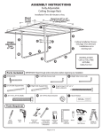
ATTACH SUPPORT BAR ASSEMBLIES
Ceiling Joist
Remove
Screws
to
Adjust
Downrods
to Desired
Length
If necessary, adjust length ofSupport Bar Assemblies(C) by removing Hex Bolts & Hex Nuts as shown.
Overlap downrods to the length desired & reinstall Bolts & Nuts.
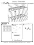
PLACE AND ATTACH GRIDS
3A
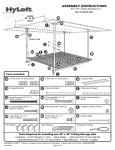
Lay both 15" Wire Grids (A) on left & right sides
of Support Bar Assemblies(C) and attach as
shown. Note: Long grid wires go on the bottom.
3B
G
E
H
four-wire clusters
nearest downrods
d.
installe
erly toda la
if impropasume te.
kg) or dor ctamen
(114
lbs. . El compra o incorre onon.
s 250 liability instaladd del limitati
e
exceed on on O si estásabilida installé
été .
if load limitati kg).
respon
liabilityents for libras (114para la n'a pas sabilitég
nité
s all
docum 250 ión si l'u de respons Pendin
ser assumetion excedela instalac kg) ou on Patent
Purchasee installasi el pesoentos de livres (114 la limitatitional
d
pour
Please sabilida docum 250 ion & Interna
1; US
los
l'installat
respon favor poids excède
nant 640903
por si le
Vea
concer 5;
sabilité ents 3; 643510
la responles docum
7; D47035
toute ter
consul 6; D47795
r assume z
Veuille D45992
L'acheteu
ement. 2;
correct s: D41615
US Patent
F
Sticker(K)
I
Lay 13" Wire Grid (B) on top of
Support Bar Assemblies(C), between
the two 15" grids (A), and Bolt Together
using 2 bolts (G), washers (I) and nuts
(H) on each side.
You have now completed the installation and are ready to load your new HyLoft Storage Unit.
(Maximum 250 lbs. per 45" x 45" unit, evenly distributed).
Place the Sticker(K) provided on a support bar for easy reference information.
Periodically (at least annually) check all connections to ensure that they remain tightly fastened
Installing Two HyLoft 45 x 45 Units:
Follow the instructions above. Multiple Units may be joined together by using Plastic TieStraps(J)
provided.