1
INSTALL INSTRUCTIONS
VERSARAC
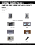
Assembled View
Center Support Beam
Wire Grids
Support Beams
18” Upright
Vertical Post
27” Upright
Vertical Post
Long Cross Beam A
Short Cross Beams
Long Cross Beam B
need more information? try, WWW.NEWAGEPRODUCTS.COM or 1 877 306 8930 for answers to commonly asked questions.
INSTALL INSTRUCTIONS
VERSARAC
SAFETY WARNING - PLEASE READ THIS FIRST
1. All VersaRac units have a rated load capacity of 600 pounds, evenly distributed, using a minimum of 1.75” lag bolt anchored into
solid wood joists or supports capable of supporting such a load.
2. Do not load more than 600lbs on to a VersaRac. Live loads (people, pets, etc) may weigh less than the rated weight capacity,
however will exert force on the rack beyond its rated capacity. As such, do not stand, jump or hang from your VersaRac.
3. VersaRac units must be installed into structurally sound overhead joists or supports. NewAge Products Inc. makes no claim to
the capacity or strength of the structure to which the units are mounted.
4. NewAge Products Inc. can not be held liable for structure failure, or damage or injury resulting from structure failure.
5. VersaRac is not intended for steel framed homes. Do not attempt mounting to steel beams.
6. Ensure all weight is distributed evenly on the rack. Place heavier objects near the vertical angle posts, and lighter
objects in the center.
7. Do not jump or climb on your VersaRac.
8. Routinely inspect your system to ensure all components are fastened securely.
TOOLS REQUIRED TO INSTALL VERSARAC:
• Eye Protection
• Rubber Mallet
• Ladder
• Drill
• Stud Finder
• 7/16” Wrench
• 7/16” Nut Driver
• 3/16” Drill Bit
• Pencil
• Measuring Tape
VERSARAC COMPONENT QUANTITIES
Description
4’ X 4’
4’ X 6’/ 4’ X 8’
1.5” x 1.5” x 4.5” ceiling mounting angle
4
4
1.5” x 1.5” x 18” vertical angle posts
4
4
1.5” x 1.5” x 27” vertical angle posts
4
4
1” x 2.75” x 48” short cross beam
4
2
1” x 2.75” x 51” long cross beam A
0
2
1” x 2.75” x 51” long cross beam B
0
2
47” Cross Supports
4
6
Center Support Beam
0
1
Steel Grid Platforms
2
4
1/4” diameter x 3/4” long bolts
12
24
1/4” nylon lock nut
12
24
1/4”diameter x 3” long lag bolt
8
8
Washers
24
48
Installation instructions, Layout diagrams and Warranty
1
1
need more information? try, WWW.NEWAGEPRODUCTS.COM or 1 877 306 8930 for answers to commonly asked questions.
INSTALL INSTRUCTIONS
VERSARAC
Installation Instructions
STEP 1
Unpack boxes to verify you’ve received all proper components for the rack you’ve purchased.
STEP 2
Identify parts by matching them to the parts list provided. You may receive extra hardware with each unit. If you do not have all parts,
please call us immediately.
STEP 3
Determine where you want to install your VERSARAC and examine the ceiling structure. Do not install more than one VERSARAC unit on any
two overhead supports.
STEP 4
Locate the ceiling joists (the horizontal studs or beams that run along the ceiling structure). If your garage has an open ceiling, you will see
the supports. If your garage has finished drywall on the ceiling, use a stud finder to locate both sides of the ceiling joists. Use a pencil to mark
both sides of the ceiling joist, and the center of the ceiling joist. If you have steel beams, you will not be able to install VersaRac. VersaRac is
not intended for steel framed homes. Do not attempt to mount to steel beams.
STEP 5
Place a ceiling mount angle on the ceiling so that the center of the holes in the mounting angle are lined up with the center of the
joist. Mark a hole in the narrow part of the keyhole, making sure the mark is in the center of the ceiling mount angle. You need to mark 2
holes per bracket. See figure 1.
Figure 1
STEP 6
Use the 3/16” drill bit to drill pilot holes for the long lag bolts, 8 holes total for the 4 brackets. Use the diagram in Step 8 to determine the
locations of the lag bolts in the ceiling.
STEP 7
Install the ceiling mount angle into the joists using ¼” x 3” lag bolts and washers provided. Place a washer between the bolt head and the
ceiling mount angle. Lag bolts must be installed into solid wood joists. Make sure the lag bolts are tight against the ceiling but do DO NOT
over-tighten the lag bolts. If lag bolts are over-tightened, they could snap the lag bolt head or strip out the hole. See Figure 2.
Figure 2
need more information? try, WWW.NEWAGEPRODUCTS.COM or 1 877 306 8930 for answers to commonly asked questions.
INSTALL INSTRUCTIONS
VERSARAC
STEP 8
Use the diagrams below to determine the locations of the ceiling mounting angles.
Note: Install at
48”, 72”, or 96”
to suit your
This measurement depends on the orientation and size of the rack you are installingapplication.
B
48”, 72” or 96”
A
48”
72”
96”
Ceiling Joist
A
Ceiling Joist
Note: The Ceiling
Mounting Angle
Bracket should be
facing outwards on
the opposite side
of the rack. See A-B
orientation.
B
LEFT SIDE
RIGHT SIDE
48”
Note: Ceiling
Mounting Angles
must be orientated in
same direction, and
measured from same
end of the bracket.
STEP 9
Identify the height from the ceiling where you would like the bottom of the shelf to be. Remember that your
storage space will be 3” shorter than this dimension due to the height of the bottom shelf beam.
need more information? try, WWW.NEWAGEPRODUCTS.COM or 1 877 306 8930 for answers to commonly asked questions.
INSTALL INSTRUCTIONS
VERSARAC
STEP 10
Place one 18” angle post and one 27” angle
post together to create one upright angle
post. The angle post that attaches to the
ceiling mounting angle should be on the
outside. The widest part of the keyholes
should be facing up on both pieces. Slide
the pieces until you get your desired overall
length. Bolt 2 angle posts together using
the ¼” dia. x ¾” long bolts, washers and nuts
provided. Use 2 washers, one between the
bolt head and angle post and one between
the nut and angle post. Place one bolt on
each side of the upright angle. See figure 3.
Tighten both bolts.
STEP 13
Install the short cross beams into the bottom of the vertical angle posts. The 1” wide flange
on the cross beam goes on top. Tap the cross beams into place using a rubber mallet to
seat the beams into the upright posts. The rivet nubs should go all the way to the bottom
of the keyholes. See figure 5. If ceiling mount angles move when you tap down the cross
beams, the ceiling angles are not tight or are not bolted into sufficient structure. Double
check ceiling lag bolts to make sure they are tight and securely fastened to the supports.
If there is not sufficient structure, remove brackets and find the proper ceiling support.
If installing the 4’x4’ Versarac please continue on to Step18.
Figure 5
Figure 3
STEP 14
Bolt together one Long Cross Beam A and one Long Cross Beam B together at the desired 8‘
length (Figure 6), or 6’ length (Figure 7) to form the long beam assembly. Use washers behind
the head of the bolt and before the nut on the opposite side. Beam A will go on the outside of
Beam B. You will notice that when you do this all the holes should line up properly.
2nd
Figure 6
Long Beam B
STEP 11
Long Beam A
1st
Repeat step 7 to form the other 3 angle
posts. Make sure all 4 angle posts are the
same length.
2nd
STEP 12
Figure 7
Bolt angle posts to ceiling angle brackets
you have already installed. Use the ¼” dia.
x ¾” long bolts, washers and nuts. Use 2
washers, one between the bolt head and
angle post and one between the nut and
angle post. See figure 4.
Long Beam B
2nd
Figure 4
1st
Long Beam A
1st
need more information? try, WWW.NEWAGEPRODUCTS.COM or 1 877 306 8930 for answers to commonly asked questions.
INSTALL INSTRUCTIONS
STEP 15
STEP 17
Install the long cross beams into the bottom of the vertical angle
posts. The 1” wide flange on the cross beam goes on top. Tap the
cross beams into place using a rubber mallet to seat the beams into
the upright posts. See Figure 8.
Place the six 47” long cross supports into the slots on the top of the
cross beams. If you have created the 6’ assembly you will have an
extra two of these left over. See Figure 10
Figure 8
Figure 10
STEP 18
STEP 16
Find the holes in the middle of the long cross beams assembly. Install
the Center Support into these holes with the remaining nuts, bolts, and
washers. The washers should behind the head of the bolt and before the
nut on the opposite side. See Figure 9
Figure 9
Place Steel Grid Platforms with the flange overhanging the cross
beams on either side of the width of the rack frame. If you have
created the 6’ assembly you will have an extra one of these grids
left over.
STEP 19
Periodically (at least quarterly) inspect your VERSARAC unit
to ensure beams are seated properly and brackets are firmly
connected to the overhead supports and securely fastened to the
supports. If there is not sufficient structure, remove brackets and
find the proper ceiling support.
8’ Configuration
OR
6’ Configuration
For specific questions regarding: product
installation, care, or cleaning, please
contact Customer Service at NewAge
Products
need more information? try, WWW.NEWAGEPRODUCTS.COM or 1 877 306 8930 for answers to commonly asked questions.
NEWAGE PRODUCTS INC. VERSARAC WARRANTY
1 YEAR LIMITED MANUFACTURER WARRANTY.
NOTE: NewAge Products Inc. assumes no liability for any personal injury, direct or indirect damages resulting from improper
installation of the VERSARAC unit.
WARNING: VERSARAC units are not intended nor designed for live loads. Do not climb in, step on, hang from or play on any
VERSARAC unit.
VERSARAC WARRANTY
THE SOLE AND EXCLUSIVE SOLUTION FOR NONCONFORMING PRODUCTS SHALL BE REPLACEMENT OF SUCH PRODUCTS
OR, AT SELLER’S OPTION, REFUND OF THE PURCHASE PRICE TO BUYER (EXCLUDING TAXES, SHIPPING, AND HANDLING
CHARGES PAID BY THE BUYER).
SELLER MAKES NO OTHER WARRANTIES, EXPRESS OR IMPLIED, AND SELLER DISCLAIMS ANY WARRANTY OF ANY OTHER
KIND, INCLUDING ANY WARRANTY OF MERCHANTABILITY OR FITNESS FOR A PARTICULAR PURPOSE, EXCEPT IN THOSE
JURISDICTIONS THAT PROHIBIT DISCLAIMER OF SUCH IMPLIED WARRANTIES.
This warranty shall not apply to loss or damage in shipping, accident, unreasonable use, or buyer’s negligence. Seller
specifically disclaims any warranty or liability for products resold in packages other than Seller’s original packing and for
products altered in any way by others after sale. Seller reserves the right to examine any defective products to determine
whether the warranty applies.
PLEASE CONSULT YOUR STATE OR PROVINCE’S LAWS. YOU MAY HAVE RIGHTS IN ADDITION TO THIS WARRANTY.
DISCLAIMER OF IMPLIED WARRANTIES; LIMITATION OF REMEDIES
IMPLIED WARRANTIES, INCLUDING TO THE EXTENT APPLICABLE WARRANTIES OF MERCHANTABILITY OR FITNESS
FOR A PARTICULAR PURPOSE, ARE EXCLUDED TO THE EXTENT LEGALLY PERMISSIBLE. ANY IMPLIED WARRANTIES
THAT MAY BE IMPOSED BY LAW ARE LIMITED TO ONE YEAR, OR THE SHORTEST PERIOD ALLOWED BY LAW. SOME
STATES AND PROVINCES DO NOT ALLOW LIMITATIONS OR EXCLUSIONS ON HOW LONG AN IMPLIED WARRANTY OF
MERCHANTABILITY OR FITNESS LASTS, SO THE ABOVE LIMITATIONS OR EXCLUSIONS MAY NOT APPLY TO YOU. THIS
WARRANTY GIVES YOU SPECIFIC LEGAL RIGHTS, AND YOU MAY ALSO HAVE OTHER RIGHTS WHICH VARY FROM STATE
TO STATE OR PROVINCE TO PROVINCE
need more information? try, WWW.NEWAGEPRODUCTS.COM or 1 877 306 8930 for answers to commonly asked questions.