1
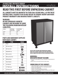
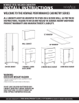
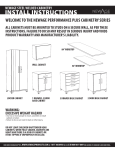
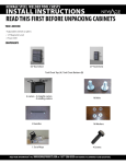
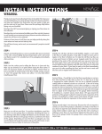
48” WORKBENCH
72” WORKBENCH
96” WORKBENCH
Workbench Series
Warning: Excessive weight hazard!
Use two or more people to move, assemble or install workbench.
Failure to do so can result in back or other injury.
For assistance, call 1.877.306.8930; for UK 0800.031.4069; e-mail at [email protected]
Parts List
LONG CROSS BEAM
WORKTOP
LONG SUPPORT BEAM FOR 96” BENCH
TOOL TRAY
SHORT SUPPORT
BEAM
TOOL TRAY DIVIDERS
LEG (A)
SHORT CROSS BEAM
LEG (B)
5/16” X 5/8”
HEX BOLTS
5/16” LOCK
WASHERS
#8-32 X 7/8”
BOLTS
#8-32 LOCK
WASHERS
AND NUTS
ADJUSTABLE FEET
#8-32 X 3/4”
SCREWS
#8-32 X 1”
SCREWS
Tools Needed
1 x 9/16” wrench
1 x 12” Magnetic Leveler
1 x #2 Phillips Bit Screwdriver
1 x Pliers
1 x Tape Measure
1 x Pencil
Parts and Hardware Supplied
Parts
48” Workbench
72” Workbench
96” Workbench
Threaded Adjustable Foot
4
4
4
Long Cross Beam
2
2
2
Long Support Beam
0
0
1
Short Cross Beam
2
2
2
Short Support Beam
2
2
2
Leg (A)
2
2
2
Leg (B)
2
2
2
5/16” x 5/8”L Hex Bolts
32
32
36
5/16” Lock Washers
32
32
36
#8 x 3/4” Wood Screws
12
12
12
#8-32 x 7/8” Bolts
2
2
2
#8 Lock Washers
2
2
2
#8-32 Nuts
2
2
2
9/32” Mini Wrench
1
1
1
#8 x 1” Wood Screws
4
4
4
Tool Tray
1
1
1
Tool Tray Dividers
4
6
8
Worktop
1
1
1
Power bar
1
1
1
Tablet Stand
1
1
1
Rated Weight Capacity
Evenly Distributed
Tray Weight Capacity (lbs)
Weight Capacity (lbs)
48” Workbench
2000
40
72” Workbench
2000
40
96” Workbench
2000
40
WARNING:
Mechanical Max load. 2000lb.
Electrical limitations is Max 15A.
Assemble The Frame
1. Select one Leg (A) and one Leg (B) and lay them opposite one another
on the floor with the leg brackets positioned on the outside of the two legs,
and facing in the same direction. See Figure 1.
2. Select one Short Cross Beam, and one Short Support Beam, and bolt the side
frame assembly together with the supplied 5/16” hex bolts and lock washers.
See Figure 1.
Note: Legs are shown being assembled upside down, as this will be easiest
for assembly and installing the top.
5. Repeat Step 4 for the opposite side to secure the two side frame
assemblies to the Long Cross Beams.
6. Secure the leg brackets to the Long Cross Beams with the supplied 5/16”
hex bolts and lock washers. See Figure 3.
7. Repeat Step 6 for the remaining leg brackets.
Fig.3
Fig.1
LEG (A)
LEG (B)
8. Place the workbench top upside down on a protected surface and mark
the top with a pencil 2” in from the sides, 1-9/16” in from the front
edge, and 3/16” in from the back edge as seen in Figure 4. This boundary
represents the correct mounting location for the steel workbench frame.
Fig.4
Rear Edge
(Stainless steel top has holes for mounting workbench tray)
3/16"
1-9/16"
3. Repeat steps 1 and 2 for assembling the opposite side frame assembly.
4. Secure the two Long Cross Beams to the post of the two legs
with the supplied 5/16” hex bolts and lock washers. See Figure 2
Fig.2
2"
Front Edge
(Stainless steel top has metal edge wrap around)
2"
9. Place the frame within the marked boundary and attach the top
with the supplied #8 x 5/8” wood screws in the 12 locations provided.
For bamboo top: Drill 1/16” pilot holes and install screws. See Figure 5.
Fig.5
Mounting
The Tool Tray
1. For Stainless Steel Top:
Install four #8 x 1” screws in the
locator holes along the edge of the
worktop, 3/4 of the way in.
Installing Bamboo Top Tray
1
Fig.1
WORKTOP
For Bamboo Top:
Place tray flush with the top of
worktop (Figure 1) and use the tray
as a guide to mark the center of the
top of the keyholes for the 4 screw
locations along the edge. (Figure 2)
+
MARK CENTER HERE
KEYHOLE ON TRAY
2. Slide the keyholes on the side of the
tray over the heads of the screws.
2
3. Slide the tray down over the screws
and tighten with a screwdriver to
secure the tray to the workbench.
3
Insert screwdriver through
the access holes for easy
installation.
5. Insert tray dividers in the desired
locations.
TRAY
Fig.2
Drill 1/16” pilot hole and install
screws 3/4 of the way in.
4. Thread in the leveling feet and
adjust as needed for leveling the
workbench.
Side View
4
5
Mounting
Power Bar
1. Insert the two #8-32 bolts into the
slots on the back of the power bar.
Secure the screws in the lower gap
towards the cord.
2.Install the power bar onto the
workbench by inserting the two
screws through the corresponding
holes on the front, or sides of the
workbench.
1
2
If installing the power bar on the
front of the workbench you can feed
the cord for the power bar through
the rubber grommets on the front
and back of the workbench.
3.Using the supplied 9/32” wrench,
fix the power bar in place with the
provided lock washers and #8-32
nuts.
3
Note: It may be necessary to grip the
ends of the bolt with a pair of pliers to
prevent the bolt from spinning while
tightening.
INSTALL TABLET STAND (OPTIONAL):
1. Angle the tablet stand and insert
through slots located on the workbench
tray and allow the hooks to engage under
the workbench tray.
Use the tablet stand with your favorite
device.
Note: Ensure your device is stable inside the stand. Newage products will not be
responsible for any damage caused to your device as a result accidental droppage or use
of this stand.
Thank you for purchasing fromNewAge Product.
NEWAGE PRODUCTS INC. WELDED WORKBENCH
10 YEAR LIMITED MANUFACTURER WARRANTY
When this product is installed, operated and maintained according to the instructions attached to or furnished with the
product, NewAge Products Inc. will replace the defective product or parts if the part fails as a result of defective materials
or workmanship for a period of ten years from the date of purchase.
NEWAGE PRODUCTS INC. WILL NOT PAY FOR:
1. Service calls to correct the installation of any NewAge products or to instruct you how to use or install them.
2. Damage resulting from improper handling or shipping of products, or products damaged by accident, misuse,
abuse, fire, flood, improper installation, acts of God, neglect, corrosion, modification or mishandling.
3. Products damaged by improperly loading beyond the specified maximum weight capacity outlined in the
instructions provided with the product.
4. Repairs or replacement when your product is used in other than normal, single-family household use, such as
a commercial environment, or handled in any way inconsistent with the installation instructions included with
the product.
5. Cosmetic damage, including scratches, dings, dents or cracks in paint that do not affect the structural or functional
capability of the product.
6. Surfaces damaged due to chemical interaction resulting in corrosion of paint or metal.
7. Replacement parts for NewAge products outside Canada, United States, or United Kingdom.
8. Replacement keys or locking mechanisms.
9. Loss of product contents due to theft, fire, flood, accident or acts of God.
10. Shipping or freight fees to deliver replacement products or to return defective products.
11. Any labor costs during the limited warranty period.
DISCLAIMER OF IMPLIED WARRANTIES; LIMITATION OF REMEDIES
IMPLIED WARRANTIES, INCLUDING TO THE EXTENT APPLICABLE WARRANTIES OF MERCHANTABILITY OR FITNESS
FOR A PARTICULAR PURPOSE, ARE EXCLUDED TO THE EXTENT LEGALLY PERMISSIBLE. ANY IMPLIED WARRANTIES
THAT MAY BE IMPOSED BY LAW ARE LIMITED TO ONE YEAR, OR THE SHORTEST PERIOD ALLOWED BY LAW. SOME
STATES AND PROVINCES DO NOT ALLOW LIMITATIONS OR EXCLUSIONS ON HOW LONG AN IMPLIED WARRANTY OF
MERCHANTABILITY OR FITNESS LASTS, SO THE ABOVE LIMITATIONS OR EXCLUSIONS MAY NOT APPLY TO YOU. THIS
WARRANTY GIVES YOU SPECIFIC LEGAL RIGHTS, AND YOU MAY ALSO HAVE OTHER RIGHTS WHICH VARY FROM STATE
TO STATE OR PROVINCE TO PROVINCE
Need more information? Try WWW.NEWAGEPRODUCTS.COM
Call At 1.877.306.8930; for UK 0800.031.4069
Or e-mail at [email protected]
NewAge Products Inc.
201 Chrislea Road, Vaughan, ON
L4L 8N6, Canada
ÉTABLI DE 48 PO
(121,92 CM)
ÉTABLI DE 72 PO
(182,88 CM)
ÉTABLI DE 96 PO
(243,84 CM)
Séries Établis
Avertissement : Cet article est très
lourd et peut représenter un danger!
Veuillez à transporter, assembler et installer cet établi avec deux personnes ou plus.
Dans le cas contraire, vous pourriez vous blesser au dos ou ailleurs.
Pour obtenir de l'aide, composez le 1-887-306-8930; pour le UK, le 0800-031-4069; envoyez
un courriel à [email protected]
Liste des pièces
LONGUE POUTRE TRANSVERSALE
PLAN DE TRAVAIL
LONGUE POUTRE DE SOUTIEN POUR ÉTABLI DE 96 PO
PLATEAU À OUTILS
PETITE POUTRE DE SOUTIEN
PETITE POUTRE
TRANSVERSALE
SÉPARATEURS POUR
PLATEAU À OUTILS
BARRE (A)
BOULONS
HEXAGONAUX DE
5/16 PO X 5/8 PO
BARRE (B)
RONDELLES
DE SÉCURITÉ
DE 5/16 PO
BOULONS
#8-32 X 7/8 PO
ÉCROUS ET
RONDELLES
DE SÉCURITÉ
#8-32
PIEDS RÉGLABLES
VIS #8-32 X
3/4 PO
VIS #8-32 X
1 PO
Outils requis
1 Clé anglaise et à douille de 9/16 po
1 Niveau magnétique de 12 po
1 Tournevis à pointe cruciforme #2
1 Ruban à mesurer
1 Crayon
1 Pince
Pièces et matériel fournis
Pièces
Atelier de 48 po
Atelier de 72 po
Atelier de 96 po
Pieds ajustables filetés
4
4
4
Longue poutre transversale
2
2
2
Longue poutre de soutien
0
0
1
Petite poutre transversale
2
2
2
Petite poutre de soutien
2
2
2
Barre (A)
2
2
2
Barre (B)
2
2
2
Boulons hexagonaux de 5/16 po x 5/8 po L
32
32
36
Rondelles de sécurité de 5/16 po
32
32
36
Vis à bois #8 x 3/4 po
12
12
12
Boulons #8-32 x 7/8 po
2
2
2
Rondelles de sécurité #8
2
2
2
Écrous #8-32
2
2
2
Mini-clé de 9/32 po
1
1
1
Vis à bois #8 x 1 po
4
4
4
Plateau à outils
1
1
1
Séparateurs du plateau à outils
4
6
8
Plan de travail
1
1
1
Barre d'alimentation
1
1
1
Support pour tablette
1
1
1
Capacité pondérale nominale
Capacité pondérale
Capacité pondérale du
uniformément répartie (lb)
plateau (lb)
Établi de 48 po
2000
40
Établi de 72 po
2000
40
Établi de 96 po
2000
40
AVERTISSEMENT :
Charge max. mécanique 2 000 lb.
Limitations électriques 15 A.
Assemblage de la structure
1. Prendre une barre (A) et une barre (B) et les placer à l’opposé l’une de l’autre par terre avec les étriers placés à l’extérieur des barres dans la même direction. Voir figure 1.
2.Prendre une petite poutre transversale et une petite poutre de soutien, et
les boulonner à la structure avec les boulons hexagonaux de 5/16 po et les rondelles de sécurité fournis. Voir figure 1.
Remarque : Les barres sur l’illustration sont montées à l’envers pour faciliter
l’assemblage du plateau.
5. Répéter l’étape 4 de l’autre côté pour attacher les deux structures latérales aux longues poutres transversales.
6. Attacher les étriers aux longues poutres transversales avec les boulons hexagonaux de 5/16 po et les rondelles de sécurité fournis. Voir figure 3.
7. Répéter l’étape 6 avec les étriers restants.
Fig.3
Fig.1
BARRE
(A)
BARRE
(B)
8. Retourner le plan de travail de l’établi sur une surface protégée et faire une marque sur la partie supérieure au crayon à 2 po des côtés, puis une autre à 1-9/16 po en partant du bord avant, et à 3/16 po en partant du bord arrière comme illustré sur la figure 4. Cette limitation marque les emplacements de montage corrects du cadre en acier de l’établi.
Bord arrière
(le plan de travail en acier inoxydable possède des trous pour installer le
plateau de l’établi)
Fig.4
3. Répéter les étapes 1 et 2 pour assembler le cadre du côté opposé.
4. Attacher les deux longues poutres transversales aux deux barres avec les boulons hexagonaux de 5/16 po et les rondelles de sécurité fournis.
Voir figure 2
Fig.2
3/16"
1-9/16"
2"
2"
Bord avant
(le plan de travail en acier inoxydable possède une bordure métallique)
9. Placer le cadre en suivant les marques et assembler le plateau avec les vis à bois #8 x 5/8 po fournies aux 12 endroits indiqués. Pour le plan de travail en bambou : Percer des avant-trous de 1/16 po et installer les vis. Voir figure 5.
Fig.5
Assemblage
du plateau à outils
1. Pour le plan de travail en acier
inoxydable :
Installer quatre vis #8 x 1 po
dans les trous le long du rebord du
plan de travail, à 3/4 de distance des bords.
Pour le plan de travail en
bambou :
Aligner le plateau à outil avec le
haut du plan de travail (Figure 1) et
utiliser le plateau à outils comme
outil de référence pour marquer
le centre au-dessus des trous où
mettre les 4 vis le long du rebord.
(Figure 2)
Percer des avant-trous de 1/16 po
et insérer les vis au 3/4.
1
Installation du plan de travail en bambou
Fig.1
PLAN DE TRAVAIL
+
5.Insérer les séparateurs de plateau
là où désiré.
MARQUER LE CENTRE ICI
TROUS DANS LE PLATEAU
2
3
Insérer le tournevis dans les trous
d’accès pour une installation facile.
4.Visser les pieds réglables et les ajuster au besoin pour mettre l’établi à niveau.
PLATEAU
Fig.2
2. Faire glisser le plateau à outils dans les trous par-dessus la tête des vis.
3. Faire rentrer le plateau à outils
dans les vis et serrer avec un tournevis pour fixer le plateau à outils à l’établi.
Vue latérale
4
5
Installation
de la barre d’alimentation
1. Insérer les 2 boulons #8-32 dans les fentes au dos de la barre d’alimentation. Fixer les vis dans le creux inférieur vers le cordon.
2. Installer la barre d’alimentation sur l’établi en insérant les deux vis dans les trous correspondants en avant ou sur les côtés de l’établi.
1
2
Si vous installez la barre
d’alimentation à l’avant, vous pouvez
passer le cordon dans les passe-fils
en caoutchouc situés à l’avant et à
l’arrière de l’établi.
3. À l’aide de la clé anglaise de 9/32 po fournie, fixer la barre d’alimentation avec les rondelles de sécurité et les écrous #8-32 fournis.
3
Remarque : Il est parfois nécessaire
de tenir le bout du boulon avec une
pince pour l’empêcher de tourner au
moment de le resserrer.
INSTALLATION DU SUPPORT POUR
TABLETTE (FACULTATIF) :
1. Aligner le support pour tablette et
l’insérer dans les trous situés sur le plateau
de l’établi en prenant soin d’enclencher les
crochets situés sous le plateau.
Utiliser le support pour tablette avec votre
appareil préféré.
Remarque : Assurez-vous que l’appareil est stable une fois dans le support. NewAge
Products n’est pas responsable des dommages causés à votre appareil en cas de chute
accidentelle ou suite à son utilisation avec le support.
Merci d’avoir fait l’achat d’un produit NewAge.
NEWAGE PRODUCTS INC. ÉTABLI SOUDÉ
GARANTIE LIMITÉE DE 10 ANS OFFERTE PAR
LE FABRICANT
Pendant 10 ans à compter de la date d’achat, lorsque ce produit est installé, exploité et entretenu conformément aux
instructions fournies avec le produit, NewAge Products Inc. remplacera les pièces ou le produit défectueux, advenant que le
bris provienne d’un défaut de matériel ou de fabrication.
NEWAGE PRODUCTS INC. NE PAIERA PAS POUR :
1. Les appels de service pour corriger l’installation de tout produit NewAge ou pour vous montrer comment les utiliser
ou les installer.
2. Les dommages causés par une manutention ou une expédition inadéquate du produit, ou des produits
endommagés par un accident, une mauvaise utilisation, un abus, un incendie, une inondation, une installation
inadéquate, un cas fortuit, une négligence, la corrosion, une modification ou une mauvaise manipulation.
3. Les produits endommagés en raison d’une charge supérieure au poids maximum précisé dans les instructions
fournies avec le produit.
4. Les réparations ou le remplacement lorsque votre produit est utilisé dans un autre lieu qu’un ménage
unifamilial normal, comme un environnement commercial, ou manipulé de toute manière incohérente avec les
instructions d’installation comprise avec le produit.
5. Les dommages cosmétiques, y compris les éraflures, les marques, les entailles ou les fissures dans la peinture qui
n’affectent pas la capacité fonctionnelle ou structurelle du produit.
6. Les surfaces endommagées en raison d’une interaction chimique entraînant la corrosion de la peinture ou du métal.
7. Les pièces de rechange pour des produits NewAge à l’extérieur du Canada, des États-Unis ou du Royaume-Uni.
8. Les clés ou mécanismes de verrouillage de rechange.
9. La perte du contenu de l’article en raison d’un vol, d’un incendie, d’une inondation, d’un accident ou de cas fortuits.
10. Les frais d’expédition ou de transport pour livrer les produits de rechange ou pour retourner des produits
défectueux.
11. Tout coût de main-d’œuvre pendant la période de garantie limitée.
EXONÉRATION DE GARANTIES IMPLICITES; LIMITATION DE RECOURS
LES GARANTIES IMPLICITES, Y COMPRIS LES GARANTIES APPLICABLES DE QUALITÉ MARCHANDE OU DE
CONFORMITÉ À UN USAGE PARTICULIER, SONT EXCLUES DANS LA LIMITE OÙ LA LOI LE PERMET. TOUTE GARANTIE
IMPLICITE QUI POURRAIT ÊTRE IMPOSÉE PAR LA LOI DOIT SE LIMITER À UN AN, OU À LA PÉRIODE LA PLUS COURTE
PERMISE PAR LA LOI. CERTAINS ÉTATS AINSI QUE CERTAINES PROVINCES NE PERMETTENT PAS LES LIMITATIONS
OU LES EXCLUSIONS SUR LA DURÉE D’UNE GARANTIE IMPLICITE DE QUALITÉ MARCHANDE OU DE CONFORMITÉ À
UN USAGE PARTICULIER. PAR CONSÉQUENT, IL EST POSSIBLE QUE LES LIMITATIONS CI-DESSUS NE S’APPLIQUENT
PAS À VOUS. CETTE GARANTIE VOUS DONNE DES DROITS LÉGAUX PARTICULIERS ET VOUS POURRIEZ ÉGALEMENT
DISPOSER D’AUTRES DROITS VARIANT SELON L’ÉTAT OU LA PROVINCE
Vous avez besoin de plus de renseignements? Consulter le site WWW.NEWAGEPRODUCTS.COM
Ou nous contacter au 1-877-306-8930; ou pour le R.-U. au 0800-031-4069
Ou envoyer un courriel à [email protected]
NewAge Products Inc.
201 Chrislea Road, Vaughan (Ontario)
L4L 8N6, Canada