1
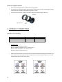
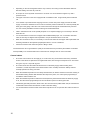
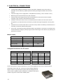
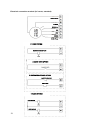
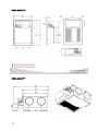
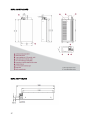
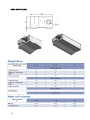
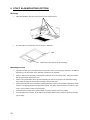
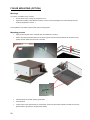
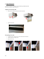
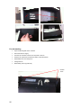
INSTALLATION AND MAINTENANCE MANUAL FAN COIL UNIT CASSETTE BORA 1. GENERALITIES ............................................................................................................................................. 2 2. PRESENTATION ........................................................................................................................................... 3 3. INSTALLATION ............................................................................................................................................. 3 Choice of the place ............................................................................................................................................. 3 Implantation ........................................................................................................................................................ 3 Reception - Storage ............................................................................................................................................ 5 Protective film ..................................................................................................................................................... 5 Installation........................................................................................................................................................... 6 Condensates evacuation .................................................................................................................................... 6 4. AIR DUCT CONNECTION ............................................................................................................................. 8 Blowing spigot (Sofit version).............................................................................................................................. 8 Fresh air intake ................................................................................................................................................... 8 Fresh air regulator module .................................................................................................................................. 9 5. HYDRAULIC CONNECTIONS ....................................................................................................................... 9 Diameter of connections ..................................................................................................................................... 9 Control valves ................................................................................................................................................... 10 6. ELECTRICAL CONNECTIONS ................................................................................................................... 11 Motors supply ................................................................................................................................................... 11 Voltage/air flow balance for EC motors ............................................................................................................. 11 Supply of auxiliary electrical resistances: Nominal current ............................................................................... 12 Electrical connection terminal (AC motor, standard) ......................................................................................... 13 Electrical connection terminal (EC motor, low consumption) ............................................................................ 13 7. DIMENSIONS AND WEIGHT ...................................................................................................................... 15 8. STAFF SLAB MOUNTING (OPTION) .......................................................................................................... 20 Warnings........................................................................................................................................................... 20 Mounting process ............................................................................................................................................. 20 FOILER MOUNTING (OPTION) ............................................................................................................................ 22 Warnings........................................................................................................................................................... 22 Mounting process ............................................................................................................................................. 22 9. MAINTENANCE ........................................................................................................................................... 23 Opening of the pivoting slab ............................................................................................................................. 23 Dismantling of the slab ..................................................................................................................................... 23 Cleaning and changing of the filters .................................................................................................................. 24 Dismantling and disinfection of the condensate drain pan ................................................................................ 24 Fan dismantling ................................................................................................................................................ 25 Long stoppage periods ..................................................................................................................................... 26 User guide ........................................................................................................................................................ 26 10. REPLACEMENT PARTS ............................................................................................................................ 26 To get all the air flow and acoustic performances, refer to the general catalogue and/or the BORA datasheet (available on www.aircalo.fr) 1 1. GENERALITIES CAUTION: before any intervention on the system and before handling any intern component, cut the power of the main circuit-breaker. Read attentively this manual before starting the installation The unit is in conformity with the Low Voltage Directive (CEE/73/23) and electromagnetic compatibility (CEE/89/336). Confide the installation to a qualified installer. The maintenance must be made only by qualified personnel. Respect safety requirements of national standards. In particular, check that you dispose of a connection on the ground with an adequate size. Check that the tension and the frequency of the power supply is like the ones necessary at the unit which will be installed. Eventually, take into account of others devices connected up at the same electric circuit. Make sure that the safety requirements of national standards have been respected over the power supply circuit Use this unit only as a part of registered applications: they do not have to be used in a laundry room or any other local with steam ironing. It should be avoiding the use of Cassettes in an atmosphere that contains oil vapors or corrosive. It is recommended to disinfect once by year, condensate drain pan to avoid the development and spreading of legionella. Keep the device away from frost. Do not install or use damaged devices. The manufacturer declines any responsibility for damage caused by the modification or mistake in electric connections or hydraulic connections. Failing to follow the electric security rules can cause a risk of fire in the case of an electric short. In case of an unusual functioning, turn off the unit, remove the electricity supply and contact specialized personnel. Unless particular conditions, Aircalo gives one year parts warranty against defects in conception or production. Are excluded defects of installation and use and also wearing parts and environment condition which damage the smooth functioning of the device that would have not be specified in the order. Failing to follow the manufacturer instructions concerning the installation or the use of the unit in conditions that exceed functioning limits indicated in this manual can lead to the loss of the unit warranty. 2 2. PRESENTATION BORA Cassette range is available in many versions : Bora standard for ceiling slabs whit metal structure Bora “thinline” for ceiling slabs with thinline profile Bora “Staff” slab in option, for a ceiling plaster Bora “Sofit” for a duct supply The all range is available in 2 heights: 300 mm and 380 mm. 3. INSTALLATION Choice of the place Avoid the following locations: Exposure to sunbeam Areas close by sources of heat. Humid locations and places where water may penetrate into the unit. Places where curtains or furniture can disturb a good circulation of the air. Location advised: A place without obstacle that can cause an unequal distribution or return of the air. Consider a location where the installation will be easier. Allow required clearances. Look for a place into the room that will guarantee a good distribution of the air. It could be easier to connect condensate drain pipe through the appropriated pipework. Implantation Units must be installed at the far end of the rooms, because the blowing is done face to the exterior side of the unit. Ensure a minimum space of 300 mm between the wall and the intake grille. In the case of an “open-space”, it would be right to put Cassettes at regular interval from each other’s in order to ensure a linear diffusion of the air through the opposite wall. Caution: the power capacity of installed units must be defined following the thermal balance and the acoustic of the locals. Units are realized with diffusion grilles which have a low induction rate. In this way, the air flow is done with an important ceiling effect (coanda). The diffusion of the air generated by the grille is maximized; therefore it is not necessary to realize any manual adjustment. It is valid for heating and cooling. Check that the panels from the false ceiling can be dismounted in order to get enough space for maintenance. All of the hydraulic and electric arrangements are put on a same lateral face (for standard unit: at the right in the way of the air). 3 Do not put the Cassettes on false ceilings which are not horizontals (because it caused water runoff). The Coanda effect could be troubled by relief accidents located in the false ceiling. It could be right to ensure that the ceiling is free from any important protuberances in the line of the blowing grille and in the width on both sides of the line. 1m for BORA 60 1.5m for BORA 120 Example of installation Bora 60: Example of installation Bora 120 4 Reception - Storage Check the conformity of goods delivered according to the order. Read and control the instructions given by the identification plate. In the case of shortages or damages, it must be done reserves on the delivery coupon of the transporter. Then, confirm this with a registered letter over 48 hours. Storage the equipment in a clean, dry place, protected from shocks, vibration and temperature fluctuation and at a relative humidity level of less than 90%. The period of storage should not exceed 1 year. Proceed with the unpacking of the device using the protections of accident prevention which are required. Recycle packaging in accordance with local laws regarding waste. It is recommended to bring the unit as close as possible to its definitive location before to unpack it. Protective film Extern faces of the device (structure and slab) in sheet metals are protected against scratches by a protective film in plastic. Before the installation stage, it is necessary to take off the film from visible surfaces, which means the frame and the slab of the unit. Note: the pivoting slab can be dismantled so it is possible to take of the film after the installation. 5 Installation Standard units Use a forklift to facilitate the installation of the unit to the ceiling. Fasten the 4 mounting clips (recommended diameter: M8) in the ceiling regarding the gap of fixation clips of the Cassette (clips are realized with slotted holes to permit a final adjusting). The mounting clips and its anchoring system must be adapted to the nature of the ceiling. Put water pipes as indicated in the « hydraulic connection » paragraph and take off the « T » profile to install the unit easily and rapidly. Raise the unit carefully taking it by its 4 mounting clips (or by the four corners) and put it into the false ceiling. If it is impossible to take off the “T” profile it will be necessary to incline the unit. Do not handle the device using pipes or valves as well as the condensate drain pan. Grab it by its 4 edges. Put up the unit horizontally with a spirit level adjusting the nuts and counternuts of threaded mounting clips. Reassemble the « T » profile and line up the unit to the profiles themselves by tightening up the nuts and counternuts (Put eventually anti-vibration/dampening washer) Finally, when all water and condensate piping connections have been made, check that the unit is horizontal and pour water into the pan to check that the evacuation is done without declination. Units with « thinline » slab It is the same that the standard unit installation. The only one modification concerns the pivoting slab which is thicker to create a necessary gap for the slab alignment with the false ceiling slabs. Unit with « staff » slab It is the same that the standard unit installation. See the corresponding section of this staff slab unit. Units « Sofit » It is the same that the standard unit installation, except for the hydraulic connection. See the corresponding section. Condensates evacuation The condensate drain pan is equipped with a smooth output DN 14 mm. It is recommended to connect the pipe of 25 mm with sealed links To ensure a good runoff of the condensates, the pipe should be slopped downwards and have a constant downslope of 2 % without curves or horizontal draining. Foresee a siphon with at least 50 mm of depth to prevent bad smells to propagate into the room. 6 If it is impossible to ensure this downslope to drain the condensates, it will be necessary to install an auxiliary draining pump with a level controller (we advise the models with floats to stop the flow in case of pump damage). Aircalo suggests the condensate pump option. The condensate drain tube must be surrounded with an insulating cover like the polyurethane, propylene, neoprene with 5 to 10 mm of thickness. For the unit equipped with a condensate drain pan which is downward removable, the condensate drain tube is connected inside the device. In this case, the drain tube passes through an orifice in the panel. In case of multiple units, the evacuation plan to realized is this one : The condensate drain tube must be put with a minimum downslope of 2 %. Its connection to sewage must be done with a siphon sized in function of the discharge pressure of the unit in order to permit an enough and permanent water evacuation. Before the starting of the unit, pour some water in the extern condensate drain pan. Check the regular runoff into the pan. In case of a mounting with condensate pump, control that the pump evacuates the water. If the runoff is insufficient, check the slope of the unit and the pipework and look for an eventual bottleneck. After the installation, try the system completely and explain to the user all the functions. 7 4. AIR DUCT CONNECTION Blowing spigot (Sofit version) Spigots that connect the blowing side (AIRCALO denomination: AIRCLIP), DN 200 mm, are provided not mounted on the unit. Spigots from the blowing side Caution: Bora Sofit casings are pre-cut on both sides. Put the spigots on the blowing side (Opposite side of the return air grille) Spigots installation (2 for BORA 60, 4 for BORA 120): Take off the pre-cut coverplates on the unit casing a screwdriver to lever it in order to break the thin metal fixation. Check that the insulating foam glued on the coverplate is correctly extracted (in some configurations, it is possible that the insulating material do not cover the coverplate). If it is needed, cut the insulating material which still staying on, with a cutter. Introduce the AIRCLIP spigot into the orifice. Apply an adequate pressure to loosen the hanging lugs behind the sheet metal of the unit casing. In this case the O-ring seal must be lightly compressed. The mechanical bond is strong. (In case of deterioration, it is impossible to remove an AIRCLIP; it has to be cut in half before putting a new one). It could be possible to put on spigots before to install the fan coil into the ceiling. Connect the ducts with clamps or adhesive tape. Make sure to cover all the surface of the spigots to ensure the best airtightness. The pressure losses generated by the ductwork must be compatible with the performance of the Cassettes. Otherwise, it should be checked that the ducts are smooth and that do not have any leaks or crushing or obstructions. The bends generate huge pressure losses and even more if its bend radius is small. Fresh air intake A side opening is foreseen on the Cassette to permit the putting up of a fresh air inlet. Clear the fresh air intake delimited by the pre-cutting and take off the coverplate in sheet metal using the same process described above. With a cutter, cut the insulating foam which is inside the fresh air inlet and make sure that you do not put insulation particles inside the unit. Standard fresh air intake spigots are DN 125 (AIRCLIP Aircalo denomination). They are provided not mounted on the unit. The fresh air intake must be done with an adequate pressure and a pre-filtered air introduced at more than 2°C. To avoid any functioning problem or excessive noise, the outside air flow must be limited at 10% of the total air flow. 8 Fresh air regulator module The unit can be equipped with a constant fresh air flow regulator. It is necessary to control the fresh air supply pressure because the functioning of the regulator must be conformed to the manufacturer impositions (in general > 70 Pa) The fresh air flow regulator or MR module slides easily into the fresh air spigot diam. 125. Regulator Spigot diam.125 Seal 5. HYDRAULIC CONNECTIONS Diameter of connections Taille BORA 60 BORA 120 Main coil 1/2" Gas female 3/4" Gas female Auxiliary coil 1/2" Gas female 1/2" Gas female Operating limits: Maximum allowable pressure: 100 Mce Minimum ambient air temperature: 5°C, maximum: 32°C Minimum water temperature: 2°C, maximum 100°C Maximum supply air temperature: 60°C Unless otherwise indicated concerning the unit, the water inlet matches with the pipe at the bottom. The water outlet matches with the pipe at the top. Respect this connection disposition when the coil is preequipped with thermo-electric control valves. 9 Depending on the unit arrangement and the way of the air, the cooling coil is located either before or after the heating coil in the way of the air. The torque to use for hydraulic connections is of 25 Nm. It is recommended to tighten it up with a spanner wrench. The upper connection of the coil is equipped with a ventilation screw. Purge entirely the air inside the coil. If it is needed to proceed with the emptying of the unit, cut the main power supply and also the water supply. Unscrew the ventilation screw in order to lower the pressure inside the coil. Unscrew partially the lower pipe of the piping or the valve. The runoff can be done through the condensate drain pan if this one was correctly installed and if the functioning was tested beforehand. Take in mind that the coil can be partially emptied. For a complete emptying, it is necessary to blow air inside the coil. It is recommended to connect the coil pipes with insulated flexible pipes. For a connection with steel tubes, ensure they are aligned and suspended to not put mechanical stress on the unit. When the connection is done, it is necessary to surround the valves and the pipes with impermeable and insulating materials as the expanded polyethylene with 5 to 10 mm of thickness. Check all connector seals when the system is filling of water. The manufacturer cannot guarantee the quality of the seals which are provided by the installer. He declines all responsibility of an eventual malfunction of the kit and for damages that can come from leaks. Control valves The motor control valves can be supply by us. In this case, they are mounted in the factory. Standard motors of the valves are planned to be supplied with 230V, their average consumption 5 VA. The valves are type 2 ways or 3 ways with by-pass. The valves must close the water inlet when there is no electricity supply. Before looking at the connections, control the position of the thermo-electric valve: normally closed from battery side and normally opened from the by-pass side. When the ambient temperature do not satisfy the thermostat, an electric resistance cause the warming of thermostatic heating element that determine the slope of the piston ; the valve opens progressively to circulate the water inside the coil. When the ambient temperature reaches the level required by the thermostat when the electricity supply is cut, the valve closes progressively from the coil side and opens from the by-pass side. Insulate the pipes with precaution, all the valve, the coil connections (chilled water side) to avoid that the condensation that could be formed does not flow in the false ceiling. It is recommended to foresee control valves which will permit to do not open the valve if the fan does not work. 10 6. ELECTRICAL CONNECTIONS The electrical installation of the device must be conformed to installation rules in the country of destination and be realized by qualified personnel following the diagrams added at the end of the manual. The power supply is 230 V single-phase + earth (Minimum functioning : 198 V, maximum : 264 V) Make the ground connection before any other connection. Check that the power supply passes by the circuit-breaker that could cut the current in all poles, respecting a gap of at least 3 mm between the contacts. All electric connections must be done on the terminal which is located in the same side of the unit arrangements. (For standard models, the device is provided with a right arrangement in the way of the air). An electric box must control each device. In the case of many devices controlled by one thermostat, it is necessary to foresee an electrical relay system. For this unit, we recommend using an electrical cable of type HO RN-F. The section of connection wires must be defined according the power input given below and the length of the cables to put (following the geometry of the locals). Motors supply AC motor BORA 60 BORA 120 Power input (W) 60 86 Current input (A) 0.27 0.38 BORA 60 BORA 120 Power input (W) 106 212 Current input (A) 0.8 1.6 EC motor Voltage/air flow balance for EC motors BORA 60 Air flow Power input Air flow Voltage Power input (V) (W) (m3/h) (V) (W) 160 2.97 6.6 180 1.55 7.6 210 3.96 10.0 240 2.08 10.7 255 4.81 14.4 440 3.81 23.0 340 6.31 28.4 580 5.0 39.2 375 6.91 36.9 705 6.07 63.7 (m3/h) Voltage BORA 120 Those values permit to nearly the adjustment to do for some regulations for EC motors. See the technical specification sheet of each unit, it shows the nominal voltage adjustment. Signal convertor of type CNV Aircalo (option with extra charge) permit to connect classic regulation systems designed for 3 ventilation speeds (low / medium / high) on EC motors with a variable speed. 11 Signal convertors CNV arrives mounted on the terminal unit. The installer is in charge to do the adjustment of the 3 air flows according to the air flow foreseen during the thermal study. Supply of auxiliary electrical resistances: Nominal current Capacity BORA 60 BORA 120 375 W 1.65 (A) - 500 W 2.20 (A) - 750 W 3.25 (A) - 1000 W 4.35 (A) - 1125 W - 4.9 (A) 1500 W - 6.55 (A) 2000 W - - 2250 W - 9.80 (A) 3000 W - 13.05 (A) Note: A reset safety thermostat is integrated to the electric resistance block. To reset it, cut the main supply of the resistance block, wait few minutes and switch the supply on again. None disassembly is necessary for this operation. The electric resistance block incorporates a second thermostat, with fuse type. In the case of the first thermostat failed, this one will interrupt definitively the supply of the resistance block. The replacement of the resistance block is necessary. Caution : Post-ventilation: it is necessary to foresee a forced functioning timing on the fan after the stop of the electric battery in order to ensure persistent energy dissipation on the resistances. For power capacities from 750W to 1000W the minimal timing is 30 seconds. For power capacities from 2000W to 3000W the minimal timing is 45 seconds. Failure to follow those recommendations can cause the deterioration of the unit even the environment. During the functioning of the electric battery, a cut of power supply can cause the onset of the security thermostat. It will be necessary to reset it. The functioning of electric resistances is forbidden when the main coil is supplied by hot water. With 2 tubes and 1 electric battery (electric resistance) system, it is forbidden to connect the lower speed (V1) on the 5 available. 12 Electrical connection terminal (AC motor, standard) GREEN /YELLOW BLUE SKY WHITE (V min) RED GREY ORANGE BLACK (V max) 2 TUBES SYSTEM HEATING OR COOLING VALVE CHANGE OVER OPTION ELECTRIC RESISTANCE OPTION SAFETY THERMOSTAT RESISTANCE 4 TUBES SYSTEM HEATING VALVE COOLING VALVE 13 Electrical connection terminal (EC motor, low consumption) GREEN /YELLOW BLACK (SUPPLY) BLUE (SUPPLY) GREY (SIGNAL 0-10V) WHITE (0 V) 2 TUBES SYSTEM HEATING OR COOLING VALVE CHANGE OVER OPTION ELECTRIC RESISTANCE OPTION SAFETY THERMOSTAT RESISTANCE 4 TUBES SYSTEM HEATING VALVE COOLING VALVE 14 7. DIMENSIONS AND WEIGHT BORA 60 STANDARD BORA 60 THINLINE 15 BORA 60 STAFF BORA 60 SOFIT 16 BORA 120 STANDARD BORA 120 THINLINE 17 BORA 120 STAFF BORA 120 SOFIT 18 BORA WITH FOILER 19 8. STAFF SLAB MOUNTING (OPTION) Warnings Staff slab installation requires mounting clips on the Cassette frame. The Staff slab is not mounted on the unit when it is delivered. Slab Maintenance door (take off for the mounting) Mounting process Install the Cassette as it is described before. The position of the 4 mounting clips will have to be realized depending on the layout plan of the Staff slab compared to the Cassette. Take the slab out of its packaging and handle it carefully to do not scratch the paint. Take the protection film off. Remove the maintenance door. Put the unit up horizontally with a spirit level adjusting the nuts and counternuts of threaded mounting clips. Adjust the height of the Cassette and align it with the slab edge. Present the Staff slab on the Cassette by aligning the fixation holes on the Cassette supports and check if there is a small play between the slab and the ceiling. The ceiling does not deform or prevent the slab to be in contact with the bottom of the Cassette. Check also that the frame of the peripheral slab covers the opening done in the ceiling. Once the adjustment is ended, fix the slab on the Cassette with the plastic fixations which are provided (use a mallet) 20 Fixingpoints Cassette Staff slab Ceiling staff Cassette Staff slab Plastic fixation 21 In the case that the false ceiling is not horizontal, it will appear a gap compared to the Cassette panel. Test again the condensate drain pan with a glass of water. Install the maintenance door on the slab (no tool required). FOILER MOUNTING (OPTION) Warnings Le Foiler is an esthetic piece, it means: Do not cause stress or hang any component on it. Unpack and install it at the ultimate moment in order to reduce handling and to avoid marking exposed surfaces (fingerprints, scratch…) The installation of the Foiler requires a slab with two fixing inserts. Mounting process Open the pivoting slab of the Cassette (see the maintenance section) Put the stop links (provided) where are the latch supports and block their extremities at the slab level, by putting the end marble into the notch of the slab. Check the limits of the slab opening by the links Close the slab. Fix the Foiler on the slab with the two countersunk screws and the inserts located in the slab. Put the two plastic fixations (provided) to disguise screw heads. 22 9. MAINTENANCE Cleaning and maintenance operations must be realized by specialized personnel. Before any intervention, switch the power off. Opening of the pivoting slab Push on the two edges of the slab from the air return side. Opened slab position Dismantling of the slab 23 In opened position, push the slab up, then to the bottom of the device The slab is freed of its rotation axes Bring down the slab Cleaning and changing of the filters The cleaning of the filters depends on the functioning conditions of the Cassette (about every 2 months). It must be changed at least once a year. The filter is placed at the air return level, inside the pivoting slab of the Cassette. To access to the filter, release the slab by pushing the both extremities of the air return side. The slab pivots to the bottom. The filter is maintained in position by to rotating clips. Turn the clips to take off the filter. Put the new filter or clean the grille and block it with the clips. Close the slab by pivoting it in the opposite direction by pushing again the two extremities, until the locking of the latches. Dismantling and disinfection of the condensate drain pan The condensate drain pan is in a moist area (in cooling functioning mode) thus develops legionellas. BORA Cassette has been designed to permit an easy dismantling of the condensate drain pan in order to realize a regular disinfection. This is recommended in hospitals in particular. Condensate drain pan with outside exit Take off one or many slabs from the false ceiling or use the maintenance door (if it is installed) to access to the condensate drain tube. Disconnect the condensate drain pipe. Open the pivoting slab of the Cassette. Take off the two foam insulation wedges from both side of the Cassette. Bring down the condensate drain pan Take off the condensate drain pan by the exterior through the opening cleared by the wedge. Clean the condensate drain pan Proceed to the assembly in the opposite way. Condensate drain pan with inside exit 24 Open the pivoting slab of the Cassette. Disconnect the condensate drain pipe. Take off the two foam insulation wedges from both side of the Cassette. Bring down the condensate drain pan Take off the condensate drain pan by the exterior through the opening cleared by the wedge. Clean the condensate drain pan Proceed to the assembly in the opposite way Wedges with foam insulation Fan dismantling Open the pivoting slab of the cassette. Disconnect the fan supply Unscrew the 2 fixation screws from the panel of the fan. Pivot the fan panel from the back and pull it toward the bottom. Dismantle the fan from the panel. Change the fan Reassembly in the opposite way Fixation screw 25 Long stoppage periods Before restarting the unit and at least once a year: Clean or change the filters of the unit. Examine the fins of the coil and if it is necessary, remove the dust Examine and clean the condensate drain pan of the unit and remove any stranger elements. Check that the electrical connections are duly tightened. User guide Once the installation and test are finished, explain to the user the main instructions of the functioning and maintenance manual, and especially pay attention of the main operating modes of the unit: How to put into service and stop How to modify the operating modes How to select the temperature Give to the user the installation manual of the unit, as well as the use and service manual, in that way, it could be used for the maintenance or in the case of an installation in another place or other eventualities. 10. 26 REPLACEMENT PARTS Piece BORA 60 (3R) BORA 60 (4R) BORA 120 2 tubes coil BAT 923 BAT924 BAT 944 4 tubes coil BAT 925 BAT926 BAT 946 Fan (AC) VEN 074 VEN 078 Fan (EC) VEN 079 2 x VEN 079 Filter G3 FTR 930 FTR 931 Filter G4 FTR 932 FTR 933 Foam support MBO107 MBO207 Spigot DN 125 VIR125 Spigot DN 200 VIR200 Diagrams and pictures are not contractual. To improve constantly the products, we reserve the right to change the characteristics, without notice it. M 7-05-13 Tel : 05 56 70 14 00 - Fax 05 56 70 14 09 14 Rue Cassiopée www.aircalo.fr 33160 Saint Médard en Jalles 27