1
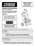
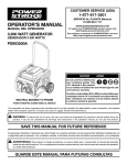
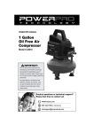
2 Gallon Oil Free
Air Compressor
Item# 22020
Owner’s Manual
DO NOT RETURN TO
STORE
Questions? Problems?
Please call our customer help line:
(800) 232-1195 M-F 8-5 CST
Or by email:
[email protected]
TABLE OF CONTENTS
Technical Data……………………………………………………………. 2
Package Contents…………………………………………………………. 2
Rules for Safe Operation…………………………………………………. 3
General Instructions for All Power Tools………………………………… 4
Specific safety Rules and Precautions……………………………………. 7
Assembly Instructions….…………………………………………………. 8
Operating instructions…………………………………………………….. 8
Inspection, Maintenance, and Cleaning…………………………………... 10
Troubleshooting…………………………………………………………… 11
Parts List………………………………………………………………….. 12
Parts Diagram……………………………………………………………… 13
Warranty Statement………………………………………………………. 14
Technical Data
1/3 HP 2 Gal. Oil Free Air Compressor
Model Number:
Volts:
Amperage:
Power Cord Type:
Power Plug Type:
Pressure Switch Type:
Air Inlet:
Fuse:
Compressor Style:
Pump Style:
Maximum Air Pressure:
Air Flow:
Air Tank Capacity:
Weight:
22020
120V~
2.6 A
18 AWG, 6 ft. Length
3-Prong Grounded
ON/OFF Switch
1/4” - 18 NPT Female Thread
3A
Oil Free
Single Cylinder
100 PSI
0.6CFM@90PSI
1.0CFM@40PSI
2 Gallons
15.5 Lbs
Package Contents:
1-Air Compressor
1-Coil Air Hose 1/4" x 25'
1-Blow Gun
1-Female Universal Quick Connect 1/4"
1-Air Chuck
1-Thread Seal Tape
1-Blow Gun Tapered Nozzle
1-Blow Gun Adapter
1-Inflation Needle
1-Air-Flow Valve
1-Female Connector 1/4"
2
Rules for Safe Operation
The purpose of safety symbols is to attract your attention to possible dangers. The safety
symbols, and the explanations with them, deserve your careful attention and understanding. The
safety warnings do not by themselves eliminate any danger. The instructions or warnings they
give are not substitutes for proper accident prevention measures.
Symbol
Meaning
Safety Alert Symbol:
Indicates danger, warning, or caution, may be used in conjunction with other
symbols or pictographs. Always follow the safety precautions to reduce the risk
of fire, electric shock and personal injury.
Note:
Advises you of information or instructions vital to the operation or maintenance
of the equipment
IMPORTANT
Servicing requires extreme care and knowledge and should be performed only by a qualified
service technician. For service, call our customer help line at (800) 232-1195 M-F 8-5 CST.
When servicing, use only genuine PowerPro Technology™ replacement parts.
WARNING:
Do not attempt to operate this tool until you have read thoroughly and understand completely all
instructions, safety rules, etc…contained in this manual. Failure to comply can result in accidents
involving fire, electric shock, or serious personal injury. Save this operator’s manual and review
frequently for continuing safe operation and instructing others who may use this tool.
Safe operation of this power tool requires that you read and understand this operator’s manual
and all labels affixed to the tool. Safety is a combination of common sense, staying alert, and
knowing how your tool works.
3
General Instructions for All Power Tools
READ AND UNDERSTAND ALL INSTRUCTIONS!!!
Failure to follow all instructions listed below may result in electrical shock, fire and/or serious
personal injury.
WORK AREA
•
•
•
Keep your work area clear and well lit. Cluttered work surfaces and dark areas invite
accidents.
Keep people not involved in the work, especially children away from the work area while
operating a power tool. Distractions can cause you to lose control of the tool.
Do not operate power tools in an unsafe environment such as explosive atmosphere,
flammable liquids, gases and dust. A spark created by a power tool may ignite the fumes or
dust.
ELECTRICAL SAFETY
•
•
•
•
•
Grounded tools must be plugged into an outlet properly installed and grounded in accordance
with all codes and ordinances. Never remove the grounding prong or modify the plug in any
way. Do not use any adapter plug. Check with a qualified electrician if you are in doubt as to
whether the outlet is properly grounded. If the tool should electrically malfunction or break
down, grounding provides a low resistance path to carry electricity away from the user.
Avoid body contact with grounded surfaces such as radiators, pipes, ranges and refrigerators.
There is an increased risk of electrical shock if your body is grounded.
Do not operate power tools in the rain or wet conditions. Water entering a power tool
increases the risk of electrical shock.
Do not stress the power cord. Never carry the power tool by the cord or disconnect the plug
from the receptacle by yanking on the cord. Keep cord away from sharp edges, heat, solvents
and oil. Replace damaged cord immediately. Damaged cords increase the risk of electrical
shock.
Use outdoor extension cords when operating the power tool outside. Outdoor power cords are
marked “W-A” or “W” and are rated for outdoor use. These cords reduce the risk of
electrical shock.
GROUNDING INSTRUCTIONS
z
z
z
z
Your compressor has a grounded, three-prong plug. If using an extension cord, it must be a
three-prong type. You must connect to a three-prong receptacle only. The third prong is for
grounding; do not remove or disable the third prong, as this will create an unsafe condition.
Common household current is 110-120 volts. As long as your compressor is rated from 110120 volts, there will be no complications in using power from a household receptacle. Never
try to plug a tool designed for 110-120 Volts into a 220-240 Volt receptacle. 220V plugs and
outlets are shaped differently to prevent this.
Only use rounded jacket extension cords, preferably listed by Underwriter’s Laboratories
(UL)
Make sure the cord is rated for outdoor use, even if your application is indoors. Outdoor use
cords have the letters “WA” on the cord jacket.
4
ALL GROUNDED, CORD-CONNECTED TOOLS:
In the event of a malfunction or breakdown, grounding provides a path of least resistance for
electric current to reduce the risk of electrical shock. Tools equipped with an electric cord having
an equipment-grounding conductor must be plugged into a matching outlet that is properly
installed and grounded in accordance with all local codes and ordinances.
Do not modify the plug provided in any way. If the plug dose not fit the outlet, have the proper
outlet installed by a qualified electrician.
The use of any Extension Cord will cause some loss of power. To keep this to a minimum and to
prevent overheating and motor burn out; use the table below to determine the minimum wire
size (A.W.G.) Extension Cord.
Use only 3-wire extension cords that have 3-prong grounding plugs, and 3-pole receptacles that
accept the tool's plug.
AMERICAN WIRE GAUGE RATING CHART
EXTENSION CORD
25
50
75
100
125
150
175
200
LENGTH (FEET)
AMPS
AWG (wire gauge)
0 to 10.0
18
18
16
16
14
14
12
12
10.1 to 13.0
16
16
14
14
14
12
12
12
13.1 to 15
14
12
12
12
12
12
12
NA
15.1 to 18
14
12
12
12
12
12
NA
NA
Use only UL approved extension cord.
Repair or replace cords as soon as damage occurs. Never use a damaged cord.
Tools with three wire grounding plugs (that look like the plug illustrated in Sketch A in Figure)
are intended for use on a circuit that has an outlet that look like the one illustrated in Sketch A in
Figure. A temporary adapter, which looks like the one illustrated in Sketches B and C, may be
used to connect this plug to a 2-pole receptacle as shown in Sketch B if a properly grounded
outlet is not available. The temporary adapter should be used only until a properly grounded
outlet can be installed by a qualified electrician. The green-colored rigid ear, lug, etc. extending
5
from the adapter must be connected to a permanent ground such as a properly grounded outlet
box.
PERSONAL SAFETY
•
•
•
•
•
•
Dress appropriately. Do not wear loose clothing or jewelry. Keep long hair in place and
contained. Keep clothing, hair and gloves away from moving parts. Loose clothing, jewelry
and hair can be snagged in moving parts.
Use common sense, stay alert and watch what you are doing while operating a power tool.
Do not use tools while under the influence of alcohol, medication, or drugs. Keep focused on
the work at hand while using a power tool to prevent personal injury.
Make sure the power switch is in the “OFF” position before plugging it into the receptacle.
This will prevent accidental starting. Carrying tools with your finger on the switch or
plugging in the tools with the switch in the “ON” position invites accidents.
Remove adjusting tools such as wrenches or keys before turning the tool on. A wrench or key
left attached to a rotating part will fly off and may cause personal injury.
Do not overreach while operating a power tool. Keep proper footing and balance at all times.
Good balance and solid footing enables better control in unexpected situations.
Always wear appropriate safety equipment. Always wear eye protection while operating a
power tool. Use appropriate dust respirators, hearing protection, hard-hat, face shield or
safety shoes as dictated by the work and tool.
TOOL USE AND CARE
•
•
•
•
•
•
•
Secure the work piece with clamps or other practical methods to provide a secure work
platform. Holding the work by hand or against your body is not secure and may lead to loss
of control.
Use the correct tool for the work. The proper tool will do the work faster and safer.
Do not use the tool if the “ON/OFF” switch is not working. Operating a tool that cannot be
controlled by you is dangerous and must be repaired before use.
Always disconnect the power cord from the electrical outlet before storing the tool, making
adjustments or adding/replacing accessories. This simple prevention will reduce the risk of
accidental starting the tool.
Store the tool in a secure place out of reach of children. A secure storage location will
prevent the unauthorized use by untrained users.
Properly maintain tools. Keep all cutting tools sharp and clean. Remove contaminants from
the tool and keep clean. Check for broken parts or binding of moving parts before use. If
damaged, have the tool serviced before use. Prevent accidents caused by poorly maintained
tools.
Use only accessories recommended for your model. Accessories suitable for one tool may
become hazardous when used on another tool.
SERVICE
•
Tool service, mechanical and/or electrical is to be performed only by qualified repair
personnel. Service performed by unqualified personnel may result in a risk of injury.
• When servicing a tool, use only identical replacement parts. Use of unauthorized parts or
failure to follow maintenance instructions may create a risk of electrical shock or injury.
NOTE: if any parts are damaged or missing, do not attempt to plug in the power cord and turn
the switch on until the damaged or missing parts are obtained and are installed correctly.
6
Specific Safety Rules and Precautions
1.
CAUTION! Your Warranty is voided if: You drop the Air Compressor. Always lift the
Air Compressor using its Handle.
2.
Do not expose to a high-dust environment. Dusty conditions may increase wear on the
Compressor.
3.
DANGER! This Air Compressor is NOT designed for and should not be used to supply
breathing air.
4.
DANGER! Never attempt to repair or modify the Air Tank (53). Welding, drilling, or any
other modification will weaken the Tank resulting in damage from rupture or explosion.
Always replace worn, cracked, or damaged Tanks.
5.
WARNING! Use only air hose with minimum rating of 150 PSI.
6.
Make sure all tools and equipment used with the Air Compressor are rated to the appropriate
capacity. Do not use any tool or equipment that operates above 100 PSI.
7.
Drain the Air Compressor every day. Do not allow excessive moisture to build up inside the
Air Compressor’s Tank. Do not open the Drain Valve (54) with more than 10 PSI of air
pressure in the Tank. Do not unscrew the Drain Valve so that more than four threads are
showing.
8.
Do not alter or remove the Safety Valve (25).
9.
Make sure the Air Compressor is located on a flat, level, sturdy surface capable of
supporting the weight of the Compressor, operator(s), and any additional tools and
equipment.
10. Do not move or transport the Compressor if the Air Tank (53) is under pressure.
11. Industrial applications must follow OSHA guidelines.
12. Never stand on the Air Compressor. Serious injury could result if the Compressor is tipped.
13. Never leave the Air Compressor unattended when it is plugged in and running. Turn off the
Compressor, and unplug the unit before leaving.
14. Do not allow children and other unauthorized people to handle or play with the Air
Compressor.
15. Do not modify the factory set pressure shutoff or startup switches. This tool will do the work
better and safer at the speed and capacity for which it was designed.
16. Avoid body contact with oils and lubricants used in the Compressor. If swallowed, seek
medical treatment immediately. For skin contact, immediately wash with soap and water.
For eye contact, immediately flush eyes with clean water.
17. People with pacemakers should consult their physician(s) before use. Electromagnetic fields
in close proximity to heart pacemaker could cause pacemaker interference or pacemaker
failure.
18. WARNING! The warnings and precautions discussed in this manual cannot cover all
possible conditions and situations that may occur. It must be understood by the operator that
7
common sense and caution are factors which cannot be built into this product, but must be
supplied by the operator.
Assembly Instructions
CAUTION! Always make sure the Compressor’s Power Switch (45) is in its “OFF” position
prior to performing any service, maintenance, or cleaning of the Compressor.
1. Handle is shipped partially attached. Remove screw (46) and position handle as shown in
figure A. Re-install screw (46) and tighten securely.
2. Install air-flow valve in pressure regulator (24). Note: Use sealing tape or silicon thread
compound on air-flow valve threads to prevent air leaking. Connect the ¼” female
connector to the air-flow valve. Remember to use the sealing tape.
HOSE CONNECTION
1. Attach an air hose to the compressor’s air outlet (air-flow valve) with the ¼” female
connector already attached. Connect the air hose to the air inlet of the tool. Use sealing tape
for best air tight connections.
Operating Instructions
To Start The Compressor:
1. Check to make sure the Air Tank’s Drain Valve (54), located at the bottom of the Air Tank
(53), is fully closed. Pull on the Safety Valve (25) to verify that it is not stuck. (See Figure B
and C)
8
Safety Valve (25)
2. Plug the Power Cord (35) into the nearest 120 volt, grounded, electrical outlet.
3. Push in the “ON” side of the ON/OFF Power Switch (45) to turn the compressor on. (See
Figure B.)
To Adjust The Air Regulator:
1. With the supplied air-flow valve attached to the Pressure Regulator (24) and the valve handle
in the “OFF” position (handle perpendicular to the outlet pipe), turn the compressor on.
When the maximum air pressure, 100 PSI, is reached as indicated by the Tank Pressure
Gauge (26), the motor will stop.
2. Turn the Pressure Regulator (24) knob to adjust Pressure Regulator (24). Turn the Pressure
Regulator (24) knob counterclockwise to decrease the PSI, turn it clockwise to increase the
PSI. When the Regulated Pressure Gauge (70) shows the pressure that you want to limit the
compressor to, the Pressure Regulator (24) is set. (See Figure C.)
3. Between the Pressure Regulator knob and valve body, a narrow ring acts as a lock-ring for
9
the knob. Rotate the ring in a counterclockwise direction and tighten it against the knob to
secure the setting. (See Figure C).
4. Attach hose to air-flow valve, then tool to hose, turn on air-flow valve to supply air
pressure shown on gauge (70) to tool.
NOTE: When the maximum air pressure, 100 PSI, is reached as indicated by the Tank
Pressure Gauge (26), the motor will stop. The Compressor will automatically restart when the
air pressure drops below 85 PSI. (See Figure C.)
To Stop The Compressor:
1. Push the ON/OFF Power Switch (45) to its “OFF” position.
2. Turn air-flow valve to off (handle perpendicular to outlet pipe). Press trigger on tool to
relieve air pressure in hose. Disconnect hose from air-flow valve
3. Relieve the Air Tank pressure and remove moisture by opening the Tank Drain Valve (54).
Turn the valve slowly counter-clockwise until the pressure is relieved. Then, retighten the
Drain Valve (54). (See Figure B.)
4. Allow the Air Compressor to completely cool. Then store the unit in a clean, dry, safe
location out of reach of children.
Inspection, Maintenance, and Cleaning
1. WARNING! Make sure the ON/OFF Power Switch (45) of the Air Compressor is in its
“OFF” position, the unit is unplugged from its electrical outlet, and air is drained from the
Tank (53) before performing any inspection, maintenance, or cleaning procedures or leaving
it unattended.
2. Before each use, inspect the general condition of the Air Compressor. Check for loose screws,
misalignment or binding of moving parts, cracked or broken parts, damaged electrical wiring,
loose air fittings, and any other condition that may affect the safe operation of the
Compressor. If abnormal noise or vibration occurs, have the problem corrected before further
use. Do not use damaged equipment.
3. Daily, purge the Air Tank (53) of all air and moisture to prevent corrosion. To do so, slowly
and carefully unscrew (no more than four threads) the Tank Drain Valve (54) until the
compressed air and condensation begins to be released from the Tanks. Allow sufficient time
for all of the air and condensation to escape from the Tanks. Then, firmly re-tighten the Drain
Valve.
4. CAUTION! All maintenance, service, or repairs not mentioned in this manual must only be
performed by a qualified service technician.
5. To replace the Fuse (43), unscrew the fuse and replace with a 250V, 3A fuse.
10
Troubleshooting
Problem
Compressor will not
start.
Low pressure.
Safety valve releasing.
Pressure switch will not
turn off compressor at
100PSI.
Cause
Blown fuse.
Loose electrical connections.
Defective pressure switch
(56).
Air leak in safety valve.
Drain valve not fully closed.
Defective safety valve.
Defective pressure switch.
11
Solution
Replace fuse.
Make sure compressor is plugged into
a working, 120 volt, grounded,
electrical outlet.
Have a qualified service technician
replace pressure switch (56).
Replace safety valve.
Close drain valve.
Replace safety valve.
Immediately unplug compressor from
its electrical outlet. Do not operate
compressor until a qualified service
technician can replace pressure
switch.
Part List
Part #
1
2
3
4
5
6
7
8
9
10
11
12
13
14
15
16
17
18
19
20
23
24
25
26
27
29
30
31
32
33
34
35
Description
Motor
Crank
Screw
Bearing (608-2RS)
Connecting Rod
Silica Gel Ring (21.2 x 2.5)
Piston Ring
Paper Pad
Hoop
Cylinder
Cylinder Washer
Silica Gel Ring (31 x 2)
Cylinder Head
Connector
Silica Gel Ring (31.5 x 1.8)
Screw (M4 x 40)
Flat Washer
Spring Washer
Fan
Screw (M4 x 10)
Tube
Pressure Regulator
Safety Valve
Tank Pressure Gauge
Two-Way Valve
Muffler Board
Screw (M3 x 6)
Copper Connector Rod
Copper Hoop
Screw (M6 x 25)
Damping Pad
Power Cord
Qty
1
1
1
1
1
1
1
1
1
1
1
1
1
2
1
4
5
5
1
1
1
1
1
1
1
1
4
2
2
4
1
1
Part #
36
37
38
39
40
41
42
43
44
45
46
47
48
49
50
51
52
53
54
55
56
57
58
59
60
61
62
70
71
72
12
Description
Motor Cover
Circuit Board
Screw (M4 x 8)
Washer
Wire Clip
Screw (M4 x 15)
Nut
Fuse (3 Amp)
Fuse Box
Power Switch
Screw (M5 x 16)
Handle
Handle Soft Grip
Cords
Flat Washer
Zip Tie
Rubber Sheath
Air Tank
Drain Valve
Rubber Foot
Pressure switch
Ball
Spring
Screw (M6 x 15)
Flat Washer
Copper Tube
Screw (M6 x 20)
Regulated Pressure Gauge
Air Flow Valve
Female Nipple ¼”
Qty
1
1
2
1
1
2
4
1
1
1
2
1
1
1
1
1
1
1
1
4
1
1
1
4
6
1
4
1
1
1
Parts Diagram
13
WARRANTY STATEMENT
FOR POWERPRO TECHNOLOGY™ PRODUCTS
PowerPro Technology™ air compressors are warranted (to the original purchaser) to be
free from defects in materials and workmanship for a period of one (1) year from the date
of original purchase. Air compressors used for commercial or for rental have a warranty
period of 90 days from date of original purchase. Please fill out the enclosed warranty card
(if applicable) and mail it to Power Pro Technology along with a copy of the receipt. The
information is required to process warranty claims.
PowerPro Technology™ will repair or replace, at its discretion, any part that is proven to
be defective in materials or workmanship under normal use during the one (1) year
warranty period. Warranty repairs or replacements will be made without charge for parts
or labor. Parts replaced during warranty repairs will be considered as part of the original
product and will have the same warranty period as the original product.
TO EXERCISE WARRANTY COVERAGE:
Do not return to retailer! For warranty and technical support call the toll-free
Customer Service Number: (800) 232-1195 and you will be informed of the nearest
authorized service center or where to ship the unit for repair. We will prearrange the repair
with the repair center should that be the procedure for this particular compressor.
WARRANTY COVERAGE:
This warranty is conveyed to the original purchaser and is not transferable.
Warranty does not extend to air compressors damaged or affected by accidents, neglect,
misuse, unauthorized alterations, use in applications beyond product design and any other
modification or abuse.
PowerPro Technology™ is not liable for any indirect, incidental or consequential damages
from the sale or use of this product. Any implied warranties are limited to one (1) year as
stated in this written limited warranty. Some states do not allow limitation on the length of
an implied warranty. Some states do not allow the exclusion or limitation of incidental or
consequential damages. This warranty gives you the specific legal right, and you may have
other rights that vary by state.
14