1
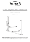
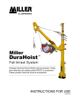
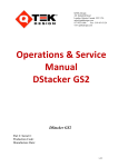
Model: Serial #: Production Code: Manufacture Date: QTEK Design 441 Industrial Road London, Ontario Canada N5V 1T6 [email protected] 877-‐453-‐1880 Fax: 519-‐451-‐3124 www.qtekdesign.com Bomber PLUS with AutoSet M9-‐60-‐1067 B4410 4242 02 01 01 June 2014 1) WARRANTY The following warranty is in lieu of all warranties, express, implied, or statutory, including but not limited to, any implied warranty of merchantability, application, or fitness for a particular purpose and any other warranty obligation on the part of QTEK Design Ltd (QTEK). QTEK warrants that its products are free from defects in materials and workmanship for a period of twelve (12) months from the date of shipment by QTEK to the original purchaser. This warranty does not apply to normal replacement of wear items such as bearings, chains, sprockets and pneumatic components. This warranty shall be voided and will not apply to any products, which have been subject to misuse, misapplication, negligence, accident, modification or tampering, nor (without limiting the foregoing) shall it apply to QTEK products used other than in QTEK products for which the same were designed. The obligation to QTEK under this warranty is limited to repair, replacement, or correction of any defective QTEK part or product determined by our inspection to be a valid warranty claim. QTEK reserves the right to examine the goods at the Buyers site, or issue shipping instructions for return to QTEK, transportation charges prepaid by the Buyer. The warranty set forth above is the only warranty made by QTEK and shall not be enlarged, diminished, or modified by, and no obligation or liability shall arise out of the rendering of technical advice of service by QTEK in connection with the sale or the product. QTEK reserves the right to make changes in designs and specifications without notice. All technical data and dimensions have been checked; however, we cannot assume responsibility for possible errors and omissions. QTEK Operations & Service Manual -‐ BOMBER with Options July 2014.docx Pg 2 2) DESCRIPTION The QTEK Bomber is a self-‐contained layer separation device. The machine is designed to remove or add any number of layers of product (such as cases or pails) that have been assembled onto a pallet. An operator using a forklift places a pallet of product inside the opening at the front of the machine and raises the pallet into the top chamber. The pallet is raised until the portion of cases the operator plans to remove are aligned with the four, urethane rubber coated compression plates called Clamps. The operator then activates the Clamps, which are powered pneumatically. The Clamps extend inward, pressing on and holding the cases above the bottom of the Clamps. The clamping pressure is adjustable and may need to be varied depending on the type, configuration, weight and sensitivity of the product being clamped. The forklift operator lowers the pallet while the clamped layers are held securely by the clamping system. Due to some challenging product layer configurations, the captured product may begin to sag or ‘belly’ downward. In order to hold such loads, the operator may utilize the Support Blade System (if the optional module is installed), which utilizes pneumatic cylinders to sends a set of 10”/ 255mm wide blades inward from the two opposite sides of the machine to support the sagging layer. Once the clamped layers are held securely and the remaining product is lowered slightly, the Product Curtain (set of metal rollers attached to a chain system; weight capacity rating: 3000lbs /1,361kg) is then extended automatically under the load. The purpose of the product Curtain is to prevent falling cases in the unlikely event that some of the captured cases were to slide down below the Clamps. The forklift operator is now able to place this captured product onto another pallet or any similar material transporting media. The QTEK Bomber can be configured to incorporate the following optional features: • Manually adjustable front and side clamp positioning designed to accommodate various product footprint size requirements • Operator Control Station with modular controls o Operator controls can be mounted on the left or right hand side of the Bomber • Clamps are available in two sizes (10 or 20 inch / 255mm or 510mm tall) configurations • AutoSet Front Clamp Adjustment Module • o In order to accommodate variations in the size of product footprints, a rapid changeover system enables the operator to adjust the travel distance of the front clamp into two different positions using an additional pneumatic control. o The AutoSet features utilizes a selector switch to move the front clamp’s starting position inward toward the rear clamp by 4 inches / 100mm. This allows the Bomber to capture product with a smaller footprint. Support Blade System incorporating a pair of 10 inch / 255mm wide support blades QTEK Operations & Service Manual -‐ BOMBER with Options July 2014.docx Pg 3 • Dual Pressure Settings Control Module o This module allows the operator to clamp the product with one of two preset clamping pressure settings. These two settings (high; low) are set to accommodate the product requirements and are determined at the time the equipment is commissioned. The QTEK Bomber is designed to minimize the need for manually lifting and stacking of cased products or 20L pails in layers on a pallet, thereby lessening the chance of injury to the worker. The Bomber provides an ergonomic solution to help minimize workers’ upper body injuries and long-‐term back problems often associated with manually handling heavy product. 3) SAFETY FEATURES The QTEK Bomber has numerous safety features incorporated into its operational procedures to further protect the operator from injuries. These include: a) Two (2) Lock Out Tag Out Switches (Electrical & Pneumatic) b) Two (2) Emergency Stop (E-‐Stop) Buttons o These are located on the operator’s control panel and on the electrical panel. o Activating either E-‐Stop arrests the machine’s function and requires a machine reset to reactivate the machine’s operations. c) Product Safety Cage o The Safety Cage contains product being raised above the clamp system and prevents loose cases from falling out of the Bomber while product is inside the upper chamber d) Protective Guarding & Warning Signage o Protective shrouds cover all moving clamp assembly components e) Clamping System Logic o When retrieving clamped product, the Clamps will not disengage until the receiving pallet blocks the Product Curtain photo eye. This is a safety measure to ensure that clamped product cannot be inadvertently or otherwise released without a forklift and a receiving pallet in place or to prevent product being dropped too far onto a receiving pallet. f) Support Blade Logic o When retrieving clamped product that is being supported by the Blade System, the Clamps will not disengage until the Blades have been retracted from beneath the captured product. This is a safety measure to ensure that clamped product cannot be inadvertently or otherwise released onto the Blades while extended. g) Product Safety Curtain o Retractable steel rollers that protect clamped product from sliding down out of the clamping system into the chamber below. o Product Curtain has a capacity rating of more than 3,000lbs / 1,361kg. o Curtain can be extended manually (in MANUAL mode) but will extend or retract QTEK Operations & Service Manual -‐ BOMBER with Options July 2014.docx Pg 4 automatically in AUTO mode as long as a forklift is positioned in front of the Bomber’s chamber. h) Pilot Operated Check Valves & Control Solenoid o In event of power loss or E-‐Stop conditions, it ensures Clamps remain in their clamped position while product is being contained i) Dual Forklift Sensing Controls o #1 -‐ Banner Switch senses vehicle presence; can only be triggered by forklift entering Bomber load area o #2 – Forklift Presence Sensing Photo Eye must be triggered within six (6) seconds of Banner Switch being triggered to ensure continued sequence operation j) Key Switch for Operational Modes o The Bomber has two operations settings: (1) AUTO mode ensures all safety features and program logics are functional. (2) MANUAL mode permits temporary operation of the equipment by overriding the system logic controls. This mode should be reserved for maintenance use only. o The Bomber is to be operated only in AUTO mode with the key removed. The Bomber must not be operated in MANUAL mode. o The selector switch is outfitted with a key that is required to switch from AUTO to MANUAL mode. 4) SAFETY RISKS The Bomber’s operating procedures outlined in this manual provide the operating protocol designed to ensure the equipment is utilized productively while securing the operator’s safety. The safety features (listed previously) are incorporated to remove all possible risk factors possible while the equipment functions as intended. Warning signage posted on the machine indicate areas where caution must be exercised when guarding is removed for maintenance purposes. Potential Risk #1: • If an operator tries to operate the Bomber continuously in MANUAL mode. Under this scenario, the safety features that are integrated into the system’s programmed logics are disengaged. Resolution: Key switch is locked into AUTO mode by the removal of the key and keeping it in a secure location under the control of the supervisor. QTEK Operations & Service Manual -‐ BOMBER with Options July 2014.docx Pg 5 5) MACHINE INSTALLATION Bomber Footprint • Standard Bomber & Bomber AutoSet: o 1980mm Wide x 2743mm Deep x 3810mm High (78”W x 108”D x 150”H) o With a total ceiling clearance of 15ft / 4.57m (with standard Clamps) o 78”W x 108”D x 174”H / 1980mm W x 2743mm D x 4420mm H o With a total ceiling clearance of 15ft / 4.57m (with 20” tall Clamps) • Bomber PLUS & Bomber PLUS AutoSet: o 142”W x 110”D x 150”H with a total ceiling clearance of 15’ (with standard Clamps) o (3606mm W x 2794mm D x 3810mm H) o 142”W x 110”D x 174”H with a total ceiling clearance of 15’ (with 20” tall Clamps) o (1980mm W x 4420mm D x 3810mm H) Requirements • Level concrete floor • Electrical: o 220V x 15 AMP Circuit for the Bomber’s electrical components o If a stand-‐alone compressor is required, a separate 220V x 15AMP circuit is required. The receptacle must be a maximum of 8 feet (2.5m) be located near the Bomber. • Compressed Air Supply: o 2.0cfm of 80psi (0.1m3 x 5.5bar) of supplied air or air supplied via a stand-‐alone compressor with a minimum 5hp motor o Air hose should be 10mm or larger o Air supply must be filtered and dried • Four (4) anchor bolts, 5/8" X 5" long (12-‐18mm x 150mm) – Supplied by SAUR Select the Proper Location It is important that the Bomber be placed on a level section of floor. If the machine is located on a sloping section of floor, the forklift will roll out of position during operation and the product will not be clamped properly. Fasten to Floor Fasten all four corners of the machine base to the concrete using concrete anchor bolts. Bumper Guards It is recommended to install forklift bumpers or bollards at the two (2) front corners of the machine guarding. This will prevent accidental damage by forklifts or other equipment. Directional Floor Marking Customer is responsible for any floor marking that operators may require. QTEK Operations & Service Manual -‐ BOMBER with Options July 2014.docx Pg 6 6) FEATURES, SETUP & ADJUSTMENT Front Clamp Adjustment When changing a product type, it may be necessary to adjust the front clamp to accommodate the new product configuration on the pallet. Consult the Clamp Setting Chart to see what setting is required. The front clamp will function in two (2) different positions. To adjust, pull the two (2) pins out of the front clamp bar, slide it along the guide rails until it has reached the desired hole position and reinsert the pins. Side Clamp Adjustment When changing a product type, it may be necessary to adjust the side Clamps to accommodate the new size. Consult the Clamp Setting Chart to see what setting is required. Pull the two (2) pins out of the side clamp bar, move the clamp until it has lined up with the desired hole position and reinsert the pins. The side Clamps have three (3) different positions. When the side Clamps reach the fully in or fully out distances, they have end stops to limit the Clamps travel. AutoSet Module (Optional) With the AutoSet module, the operator is able to advance the front clamp’s starting (Clamps open) position inward 4in (10cm) prior to capturing a load. This enables a smaller footprint load (distance between front and rear of the pallet layers) to be captured without manually adjusting front clamp pin settings. NOTE: QTEK Bombers equipped with the AutoSet feature have only one (1) front clamp setting that is not adjustable. Support Blade Module (Optional) This feature provides a set of 10in (25cm) wide Blades that can be inserted from each side to support a captured load that might not otherwise be held securely. The operator deploys the Blades in between the layers being split as soon as the path of the Blades will clear the top of the lower layer below the split. Air Pressure Regulation & Dual Pressure Module (Optional) The main supplied air pressure regulator / filter is located on the left outside wall towards the front the machine and is preset at 80psi (5.5bar). The Clamp Pressure may be adjusted depending on the product being clamped. (Dual Pressure settings are adjusted separately.) The goal is to have the least amount of clamp pressure possible but still be able to hold product securely. The pressure set points for the Bomber’s AutoSet, Support Blades, and Dual Pressure features are adjusted individually and operate within pressure ranges of: • Clamping System: 15 – 65psi (1.04 – 4.5bar) • Support Blades: 15 -‐ 60 PSI (1.04 – 4.2bar) • Dual Pressure: High & low settings are finalized by client product requirements. QTEK Operations & Service Manual -‐ BOMBER with Options July 2014.docx Pg 7 AUTOMATIC Mode The QTEK Bomber is to be operated in the AUTO setting at all times which enables the machine to function in an automated state. In this mode, the Product Curtain will extend under a clamped load as the operator leaves the Forklift Sensing Area in front of the chamber. Upon returning to the sensing area and being sensed by both sensors (Banner Switch and Forklift Presence Sensing Photo Eye) the Curtain will automatically retract assuming the Curtain Photo Eye is not blocked by sagging product that is being held by the Clamps. Other AUTO mode features include: • In AUTO mode, the operator can extend the Product Curtain manually as long as the Curtain Photo Eye is not blocked. The operator can simply push the Curtain actuator button before leaving the chamber. • The Banner Switch and the Presence Sensor Photo Eye must sense the forklift entering the chamber within six (6) seconds of each other in order for the Bomber to operate. If these two sensor contacts are not made within the 6-‐second window, the red light will flash on the Control Station indicating this fault and the controls rendered inoperable. To reset the fault, the forklift must back out until it is no longer being sensed and then return as usual. • The Support Blade System will enable an operator to hold product layers that would normally ‘belly’ down too low in the center. The Blades, controlled by the operator, are extended under the center of the layer being split from the pallet. The Bomber’s PLC (Programmable Logics Controller) safety protocol will not allow clamped product to be released while the Blades are in their extended “In” mode. • Product Curtain will not extend or retract in automatic mode if the red light is illuminates with a solid red light which indicates that the Curtain Photo Eye is blocked either by sagging product, a raised load too close to the clamped load, a piece of stretch wrap hanging down in the photo eye’s line of sight, etc. The operator will need to determine the reason for the error and rectify it before proceeding. • While the Product Curtain is moving (extending or retracting) the Clamp actuating button are rendered inoperable. Once the Product Curtain is fully retracted, the Clamp actuating chains will become functional again. • The Product Curtain cannot move for 12 seconds after being extending or retracting. After this reset period, the Curtain will now be functional again. If the operator has extended the Product Curtain and fails to leave the sensing area before the end of this 12-‐second period, the Product Curtain will automatically retract assuming the Curtain Photo Eye has not been blocked. To re-‐extend the Product Curtain, the operator will need to wait another 12 seconds before being able to activate the Product Curtain. • If the green light is flashing (indicating “Low Clamping Pressure”), the Product Curtain will not retract in AUTO mode. The Bomber must be put into MANUAL mode. Lift a pallet up to 2” -‐ 4” (5 – 10cm) below the Product Curtain, retract the Curtain, lift the pallet up to support the load, and unclamp the load. • The AutoSet feature will change the Front Clamps position only if the Clamps are not QTEK Operations & Service Manual -‐ BOMBER with Options July 2014.docx Pg 8 engaged and the Product Safety Curtain Photo Eye is not blocked by product being raised into Clamps. • The Dual Pressure module (changes the clamping pressure from Low to a High preset pressure or vice versa) will change the clamping pressure only if the Clamps are not engaged and the Product Safety Curtain Photo Eye is not blocked by product being raised into Clamps. • The Operator Station’s red light is used to indicate two separate machine functions. o FLASHING RED: Indicates (1) a fault when the Banner Switch and Forklift Presence Sensor Photo Eye are not contacted within the 6-‐second period of entry into the chamber. To reset fault, back out of the sensing area until red light stops flashing. (2) The Banner Switch needs to be reset. o SOLID RED: The Product Curtain Photo Eye (shooting a beam diagonally just above the Safety Curtain’s travel path) is used to verify whether or not the Product Curtain’s path is clear so that the Curtain is able to extend or retract unencumbered. Solid red on the operator’s console means the Curtain’s travel path is blocked. ! NOTE: In order for the Clamps to release, the operator must raise the receiving pallet high enough to just block the Product Curtain Photo Eye. This will cause a solid red light to appear and the Clamps actuator button can now be used to release the product. This safety feature is designed to prevent product from being dropped without a receiving pallet beneath it. • A cycle counter on the panel counts the number of times the Clamps are closed while the machine is in AUTO mode. QTEK personnel can reset the counter if required. • Loss of electrical power or pneumatic line pressure causes the Pilot Operated Check Valves to lock the air in the airbags thus ensuring a clamped load will not be dropped. MANUAL Mode • This manual setting overrides all PLC automatic functions and allows for the operation of the Clamps, Blades and Product Curtain. PLEASE NOTE: Extreme caution should be exercised when operating in MANUAL mode due to the deactivation of the operational safety feature functionality. • MANUAL mode is to be used strictly for maintenance purposes (checking operations of the Clamps, Product Safety Curtain, Blades, Dual Pressure or for changing yellow Curtain rollers) and for overriding the AUTO mode functionality in the event of a problem with the Clamps, Blades or Product Curtain operations. • To limit the use of MANUAL mode operations to maintenance and issues resolution functions only, the key from the selector switch can be removed once placed in AUTO mode, which locks the machine in AUTO mode. • Loss of electrical power or pneumatic line pressure causes the Pilot Operated Check Valves to lock the air in the airbags thus ensuring a clamped load will not be dropped. QTEK Operations & Service Manual -‐ BOMBER with Options July 2014.docx Pg 9 7) QTEK BOMBER OPERATIONS Starting the QTEK Bomber • Turn the main electrical power switch to “ON.” • Turn the selector switch to “AUTO.” • Gently twist the red “E-‐Stop” button on the electrical panel clockwise until it pops out. (PLEASE NOTE: If button is twisted too vigorously, it will disconnect the wiring connection and will render the switch and the Bomber inoperable.) • Check that the main air pressure regulator gauge reads a minimum of 65 psi. Verify that the air pressure shut off is not locked out or disengaged. • Verify proper air pressure on the Clamps pressure gauge (plus Blades &/or Dual Pressure if installed) • Press the green “RESET” button once. The “RESET” button light should turn solid green. The machine is ready to operate. a. NOTE: If the “RESET” button light blinks, the following need to be verified; i. Product Curtain Photo Eye is not blocked. The sensor’s red light should be illuminated when the sensor is clear. When it’s blocked, the small red light will be off. ii. Forklift Presence Sensor Photo Eye is blocked or has not be misaligned. The sensor’s green light should be on when it is properly aligned. iii. Retract Curtain Prox Switch is not made due to a Product Curtain travel issue. iv. Banner Switch sensing area is not clear of metal objects or has faulted out – both scenarios will be indicated by two yellow lights on the Switch. • 1. Removing the metal object should clear the Switch and will show one small green LED output light. 2. If faulted out, a. Push & hold the “TEACH” button for 2 seconds. b. When the red light comes on, release button. Quickly push the “TEACH” once more and it will flash 12 times. The single green LED means it is now reset. 3. If the Banner Switch sensitivity setting (6 different levels) needs to be increased: a. Push & hold the “TEACH” button for 2 seconds. b. When the red light comes on, Release button. c. Double-‐click TEACH button to change to RESET mode. The red light flashes to show the current sensitivity setting (one flash = setting 1; two flashes = setting 2; three flashes = setting 3; etc) d. Push once to increase the level. e. Double-‐click TEACH button to reset to RUN mode. QTEK Operations & Service Manual -‐ BOMBER with Options July 2014.docx Pg 10 Operating the Machine 1. Ensure that the system pressure and the Clamp settings are correct for the palletized product to be handled. Incorrect settings can result in serious damage to the product and potentially the clamping system. Verify Clamp positions with Product Clamp Settings Chart list below. • Cut the stretch wrap between the layers being split and pull it up slightly from the bottom layer to be clamped. • Forklift enters the Forklift Sensing Area (approx. 6-‐8ft / 2-‐3m in front of the Bomber.) The Banner Switch will initially sense the forklift as it approaches. (Banner Switch has a single green LED when in READY mode and is not sensing a forklift. It will show a yellow and green LED lights when sensing a forklift in the Sensing Area.) The forklift must continue toward the Bomber chamber and block the second sensor, the Presence Sensor Photo Eye. As long as both sensors have been contacted within 6 seconds of each other, the Bomber Clamps, Support Blades, Dual Pressure and Product Curtain features become active. a. NOTE: If contact with the two sensors has not been made within 6 seconds of each other, the red light at the top of the Operator Controls Station will flash indicating it has entered a fault mode (Bomber will not operation.) i. To reset the fault, the forklift backs out of the Sensing Area until the flashing red fault light stops. The operator should proceed into the Bomber’s Sensing Area again. • OPTION: If the Bomber is equipped with AutoSet feature, the operator should select either the IN or OUT position setting using the selector switch on the Operator Station. This will move the front Clamp’s starting position inward by 4in / 10cm. • OPTION: If the Bomber is equipped with Dual Pressure feature, the operator should select either the HIGH or LOW pressure setting using the selector switch on the Operator Station. This will clamp the product with the appropriate preset pressure. • Operator brings the load into the chamber until the product makes gentle contact with the back wall before raising the load up between the four open Clamps. a. NOTE: If the product is overhanging the pallet on either the front or backside of the pallet, make sure the side with the overhanging cases is positioned against the back wall. b. Before raising product up into the Clamps, the operator must ensure there is an 8-‐10in / 20-‐25cm gap between the product face and the forklift’s mast. This enables the load to be raised inside the front Clamp while the mast remains outside the Clamp. It will prevent damage to front Clamp as well as allowing the Clamp to have maximum travel (back to front) during the clamping and unclamping steps. • Operator must ensure the product is centered (left to right) between the sidewalls before raising the load. This ensures all four Clamps squeeze the layers evenly. • Raise the load until the bottom of the desired layer to be clamped is level with and QTEK Operations & Service Manual -‐ BOMBER with Options July 2014.docx Pg 11 as close as possible to the bottom of the side Clamp. • Operator engages the Clamps by pushing the “Clamps On/Off” actuator button. Do not hold it down – simply push and release. The front and rear Clamps engage first with the side Clamps engaging 0.5 seconds later. • The Clamps will progressively squeeze the load as airbag pressure is built up (usually taking 2-‐3 seconds.) Once the preset clamping pressure is achieved, the green “Clamps On/Off” button will illuminate to a solid green light. At this point, the blue “Blades” button will also light up indicating the Blades are now operational. To ensure the clamping has successfully grasped the product, slowly lower the pallet 2-‐ 3” to verify the bottom of clamped layer is holding well and all cases are contained. a. SUPPORT BLADES OPTION: For products that require support to prevent the captured layers from ‘bellying’ down, the operator should deploy the Blades in between the layers being split as soon as the path of the Blades will clear the top of the lower layer below the split or the pallet if removing the bottom layer. ii. To engage the Blades, the operator needs to lower the unclamped product just until the Blades’ travel path will not hit the top of the lowered product as they travel inward beneath the layer being split off. The yellow arrow on the black Blade housing indicates the travel path of the Blades. Operators should verify this using the monitors iii. IMPORTANT: In order to prevent the Blades from being driven into the side of the ‘bellying’ product layer instead of going beneath it to provide support, lower the product just until the Blade path is clear and then stop lowering. The Blades will push their way in between the upper clamped layer and remaining pallet layers. iv. To reverse the Blades’ direction of travel (either in or out) after the button has been pushed, simply push the “Blades” button again to change the Blades direction. This is helpful if the Blades start to hit the sides of the product or the pallet, which can occur if the pallet was not lowered sufficiently before the Blades were deployed. Simply lower the pallet just enough to reinsert the Blades. • The operator lowers the remaining, unclamped product an additional 4-‐5in / 10-‐ 13cm and visually verifies that the Clamps are holding product satisfactorily and the Blades (if optional module installed) are supporting well. At this point, the red light switches off, indicating that it is safe for the Product Curtain to extend. IMPORTANT: If the operator decides to extend the Curtain manually rather than allowing the Bomber to do so automatically, he/she must ensure that the top of the lowering product is below the path of the yellow Curtain rollers. This should be verified using the monitors. a. NOTE: During this phase, a solid red light will be on if the Product Curtain Photo Eye is blocked by either product that was clamped too low, product that has ‘bellied’ down due to insufficient clamping pressure, is obstructed QTEK Operations & Service Manual -‐ BOMBER with Options July 2014.docx Pg 12 by stretch wrap or until the operator lowers the remaining product below the Product Curtain Photo Eye. b. If the product is clamped too low, unclamp the product, raise it appropriately and reclamp again. • The Product Safety Curtain will operate under the clamped load when: a. The red light is not illuminated and the operator pushes the yellow button marked “Curtain.” b. The forklift backs out of Forklift Sensing Area and the Curtain will extend automatically. • Once the load is clamped securely, the operator may lower the remaining load and exit the chamber. • When the operator returns to retrieve the clamped load, the receiving pallet must have the same 8-‐10” gap between the product and the forklift’s mast. When the forklift reenters the sensing area, contact with the Banner Switch and Forklift Presence Sensor Photo Eye must be made within 6 seconds of each other, which will cause the Product Curtain to retract automatically. If the Product Curtain Photo Eye is blocked (possibly by product that has slowly ‘bellied’ down) a solid red light will illuminate. The Curtain will not retract automatically under this scenario. NOTE: If for some reason product is found resting on the Curtain, the operator will need to survey the situation. Care must be exercised in trying to rectify this scenario. a. Operator can utilize the Temporary Curtain Override that gives the operator manual control of the Curtain’s function for 10 seconds only. The other option is to switch from AUTO to MANUAL mode on the electrical panel. (The selector switch key is required for this step.) b. It is important to determine how much product weight is actually resting on the Curtain since the Curtain’s drive motor is capable of retracting it while a small amount of product is resting on the Curtain. SCENARIO A: MINIMAL WEIGHT If minimal amount of cases are found to be resting on the Curtain (typically a 24 x 24in / 60 x 60cm area in the middle of the layer) and there are no cases jammed between the rollers, the motor may be used to retract the Curtain. • • STEP 1: Raise an empty pallet up to within 1 inch below the yellow Curtain rollers. • Step 2: Push the Curtain button to retract the rollers. As they retract, the ‘bellying’ product should drop onto the waiting pallet. • Step 3: Retract the Blades (if deployed) once the Curtain has successfully retracted from beneath the load. • Step 4: Unclamp the load as soon as the Blades are retracted. QTEK Operations & Service Manual -‐ BOMBER with Options July 2014.docx Pg 13 SCENARIO B: EXCESSIVE WEIGHT If the majority of the clamped product appears to be resting on the Curtain, attempts to use the drive motor to pull the Curtain from beneath the load will exceed its capacity and will trip the breaker. • Step 1: Raise an empty pallet up until it makes contact with the yellow Curtain rollers. Make sure the pallet is level with the rollers and makes even contact across the Curtain. • Step 2: Push the Clamps button to release the product weight onto the rollers, which are supported by the pallet. • Step 3: Gently raise the pallet with the product weight no more than ¾” and reclamp the product. This step raises the product slightly, lessening the weight on the Curtain rollers making it possible to retract the Curtain using the drive motor. NOTE: Raising the pallet beyond this will disconnect the rollers from the side chains and possibly break the chain links. • Step 4: Lower the empty pallet again to within 1 inch below the yellow Curtain rollers. • Step 5: Push the Curtain button to retract the rollers. As they retract, the ‘bellying’ product should drop onto the waiting pallet. • Step 6: Retract the Blades (if deployed) once the Curtain has successfully retracted from beneath the load. • Step 7: Unclamp the load as soon as the Blades are retracted. • The operator raises the receiving pallet up to within 2-‐3in / 5-‐8cm below the clamped product or the Blades (if previously extended.) This will block the Curtain Photo Eye sensor, causing the red light to illuminate, which will now enable the Blades to be retracted (if deployed) and the Clamps to function. The operator pushes the “Blades IN/OUT” button to retract the Blades, then the “Clamps ON/OFF” button, which will release the load and lower the product onto the receiving pallet. NOTE: If the red light is not illuminated, raise the receiving pallet until the light illuminates. a. When retrieving clamped product, the Clamps will not disengage until the receiving pallet blocks the Product Curtain photo eye. This is a safety measure to ensure that clamped product cannot be inadvertently or otherwise released without a forklift and a receiving pallet in place or to prevent product being dropped too far onto a receiving pallet. b. If the receiving pallet is raised up too high, contacting the Blades, clamped product and/or the Clamps, damage to the Blades and/or Clamps will occur. • Operator lowers the pallet to the floor, picks up the pallet closer to the mast and exits the chamber. QTEK Operations & Service Manual -‐ BOMBER with Options July 2014.docx Pg 14 8) MAINTENANCE & INSPECTION In order to maintain the QTEK Bomber in peak operational condition, the owner should perform the following inspection and service: Daily Inspections: 1. Check that all springs are present and in good working condition. All four Clamps should appear parallel or square to the sidewalls. If one of the Clamps is not parallel or square to the sidewall, determine which spring is defective. Replace as necessary. 2. Check that all Product Curtain rollers are present and straight. If any rollers are bent, these should be removed and replaced immediately to avoid Product Curtain damage. Weekly Inspections: 1. 2. 3. 4. 5. Switch from AUTO mode to MANUAL mode. Check proper operation of systems. Inspect chamber surfaces for damage that could cause damage to products. Drain any water or contaminants from the air filter reservoir. Check oil level of air compressor (if using a stand alone compressor.) Drain the Bomber air accumulation tank and the air compressor (if using a stand alone compressor.). 6. Remove debris around the machine and in the chamber. 7. Wipe the Clamps’ rubber surface with a mild detergent solution to remove any excess dirt or debris. 8. If Bomber is equipped with electrical panel heating system, check to see that the heating units inside the panel are in good working order. Every Three (3) Months: 1. 2. 3. 4. 5. 6. 7. Clean air compressor (if using a stand alone compressor.). Check tensions of safety roller chain and drive chain. Inspect the air stroke actuators for air leaks and damage to the rubber surfaces. Verify that safety guards are installed and are not damaged Switch to MANUAL mode to verify stack lights are working. Check both E-‐Stops to ensure proper function. Check for structural damage to Clamps. If the rubber clamp surface is dirty, clean with a mild detergent solution. 8. Check for loose or broken fasteners. 9. Rotate each individual Product Safety Curtain (yellow) roller by hand and assure that these are not bent. Bent rollers must be replaced to prevent jamming in machine. 10. Inspect each Product Curtain roller for proper attachment to the roller chain. 11. Assure that the safety markings on the floor are visible (if previously installed.) 12. Inspect gear reducer oil level. QTEK Operations & Service Manual -‐ BOMBER with Options July 2014.docx Pg 15 Annual Inspections: 1. Change Reducer oil. 2. Grease the four (4) flange bearings at the rear of the machine (1 shot of lubricant.) 9) LOCK OUT TAG OUT (LOTO) PROCEDURE STEP 1: Ensure that no product is being held in the Clamps and that the Product Curtain is retracted and not extended. STEP 2: Depress the E-‐Stop button. This will disable the system. STEP 3: Turn the electrical panel power switch from “ON” to the “OFF” position, which will disconnect all electrical power to the unit. Expose the lock out tab on the power switch by lifting the red center tab out of the center of the power switch. Insert tag lock. STEP 4: Disengage the air supply by pushing the yellow tab on right side of the air regulator into the down position. This will dump the air in the system and will expose the lock out location. Insert tag lock. STEP 5: To verify that the system is non-‐functional, press the green “RESET” button. It should not illuminate indicating the system is safe to be handled. QTEK Operations & Service Manual -‐ BOMBER with Options July 2014.docx Pg 16 10) TROUBLE SHOOTING Issue Encountered Cause / Reason Solution(s) Operator did not activate the Whether in MANUAL or AUTO modes, the operator must pull the Product Curtain control chain Curtain. marked “CURTAIN” to activate it. Product Curtain does not retract. Forklift Presence Photo Eye has Forklift must be in the sensing area of the chamber for the Bomber’s clamping and Product not detected a vehicle. Curtain features to be active. Once a forklift returns and is sensed, the Curtain will retract automatically if it was in the extended state. Product Curtain Photo Eye just 1) above the Safety Curtain rollers is blocked. The red warning 2) light will be illuminated. If stretch wrap is blocking the eye, turn off the machine and remove the blockage. Turn the machine back on and reset the machine. The green panel RESET light will be solid. If the product has sagged and resting on the rollers, remove the front cage and manually remove any cases not clamped. Alternatively, position an empty pallet 1” below the rollers. Ensure the forklift Present Sensing Photo Eye is blocked and turn the machine to MANUAL mode. Pull the Product Curtain chain to retract it and drop the product onto the pallet. Remove all products and return the machine back to AUTO mode. E-‐Stops has been pushed. Reset this E-‐Stop button. Turn the key switch to MANUAL and then back to AUTO mode to proceed with normal operations. Bent or damaged rollers that may be hindering the Curtain from travelling. Switch to MANUAL mode. Determine which roller(s) are bent and replace as needed. To remove roller, loosen setscrew on the white plastic end. Slide it into the yellow tube, which will enable the roller tube to be removed from chain. NOTE: Even slightly bent rollers should not be used in the machine. Ensure all rollers are straight. Extend Proximity switch is not Look in the upper and lower inspection windows on the machine’s left rear corner guard and made. verify whether the Curtain Extend Proximity switch has been made or not. Visually verify that no obstruction is impeding the Curtain’s motion. If required, turn the power switch to OFF. Remove the large back guards to access any obstructions. Once cleared, switch to MANUAL mode and activate the Curtain to reset its travel cycle. Run the Curtain through several cycles to ensure proper operation. Return key switch to AUTO mode and proceed as normal. Banner Switch has tripped out If the Banner Switch is showing two (2) LED lights without a forklift present, it needs to be and become non-‐operational. reset. To reset, push and hold the “TEACH” button for two (2) seconds on the side of the Banner Switch Release the button once the red light illuminates. Push the TEACH button once quickly and release. It will flash twelve (12) times while it resets itself. Once reset, the left yellow light goes out and the right side light will become green and stay on until it senses a forklift entering the sensing area. NOTE: When resetting the Banner Switch, make sure the QTEK Operations & Service Manual -‐ BOMBER with Options July 2014.docx Pg 17 chamber and the sensing area are clear of all objects, particularly metal items, as this will negatively impact the Banner Switch calibration. Product Curtain won’t Product Curtain Photo Eye just 1) If stretch wrap is blocking the eye, turn off the machine and remove it. Turn the machine above the Safety Curtain rollers back on and reset the machine. The green panel RESET light will be solid. extend. is blocked. The red LED (on this 2) Product is clamped too low and is blocking Photo Eye. Unclamp the load, raise it up photo eye) will not be appropriately (within ½” of the clamp bottom) and reclamp load. illuminated. 3) After clamping product, the operator has not lowered the remaining product pallet enough to clear the Product Curtain Photo Eye. Lower to 4-‐6” below the clamped load and pull the Curtain control chain again. 4) The 12-‐second Curtain reset has not elapsed since its last movement. Wait approximately 12 seconds and then pull the Curtain control chain again. Product is sliding out Product’s layer configuration 5) Check to see that product cases are not missing. Replace missing cases to complete the has large voids in each layer. layer(s). of the Clamps. Product is too heavy for current Adjust clamp regulator pressure and test the product clamping again. Adjust in 5 PSI pressure setting. increments until desired results achieved. Increase pressure up to a maximum of 60 PSI. Product is sliding out Stretch wrap on the sides is allowing heavy product to of the Clamps. slowly slide down. For heavy product or those with weak cases (ex: cans), cut stretch wrap and expose lowest 3 or 4 layers to be clamped. NOTE: It is advisable not to leave the stretch wrapped product in the clamped position for extended periods of time. Power and/or air supply are turned off. Turn on the Bomber electrical power and air supply. Verify that the air accumulation tank gauge reads at least 60 PSI. Air pressure shut off valve is locked out. If the yellow flat tab on the shut off valve is pushed down, exposing the holes in the tab, it is locked out. To engage it again, hold the yellow button down and lift up on the yellow tab. Air pressure is too low to allow Ensure the air regulator pressure is set to 35 PSI or higher. Maximum is 60 PSI. for the safety check values to operate and release the air Clamps will not open. bags pressure. The current clamp settings are Check the front and/or side Clamp setting position (which hole the pins are in) to ensure the insufficient. Clamps travel limit has been reached for the current setting (See Figure 6a.) If the Clamps have reached their travel limit, the safety chains will be taut when attempting to squeeze the product at issue. If so, adjust the Clamp to a setting that is conducive where the Clamps’ safety chains have some play in them once product is clamped. (See Figure 6b) QTEK Operations & Service Manual -‐ BOMBER with Options July 2014.docx Pg 18 Clamps will not capture product. Product Safety Curtain is extended. In AUTO mode, product Clamps are rendered inoperable when the Product Curtain is extended. This prevents releasing clamped product onto the Product Curtain. Power and/or air supply are turned off. Turn on the Bomber electrical power and air supply. Verify that the air supply is connected to the unit. Support Blades are deployed beneath a load. Retract the Blades. Once they are out, the Clamps actuator will function. Forklift presence is not detected. Forklift must be in the sensing area of the chamber for the Bomber’s clamping and Product Curtain features to be active. The PLC needs to be reset. Ensure that the power switch is set to ON. Verify neither of the E-‐Stops has been pushed. Next, turn the key switch from AUTO to MANUAL and then back to AUTO again. Push the RESET again to energize the system. Banner Switch Sensing Area is not clear of metal objects. 1) 2) Remove metal object(s) from Sensing Area and reset panel. If the Banner Switch is showing two (2) yellow LED lights without a forklift present, it must be reset. To reset, make sure Sensing Area is clear of any metal objects. Push and hold the “TEACH” button for two (2) seconds on the side of the Banner Switch. Release the button once the red light illuminates. Push the TEACH button once quickly and release. It will flash twelve (12) times while it resets itself. Once reset, the left yellow light goes out and the right side light will become green and stay on until it senses a forklift entering the sensing area. NOTE: When resetting the Banner Switch, make sure the chamber and the sensing area are clear of all metal objects, particularly forklift equipment, as this will negatively impact the Banner Switch calibration. Retract Curtain Prox switch is not made 1) Remove back guards closest to the panel. Verify that there is nothing impeding the Curtain’s travel (ex: bent roller, etc) Clear obstruction and reset system. If the Curtain has travelled past the prox switch and activated the travel limit switch, contact QTEK for instructions. Machine RESET light on the panel is blinking. 2) An issue with one of the sensors or photo eyes. 3) Verify that the Curtain Photo Eye is not blocked. Ensure the Forklift Sensing Photo Eye is not misaligned due to damage. The photo eye sender (left side) should normally have two lights show on its collar when aligned properly and clear of obstructions. If only one light is illuminated, the alignment is out. Realign and reset panel A circuit breaker has been tripped. 4) Turn off the power. Open the panel and identify the three (3) breakers. Reset breaker as necessary. Close panel and follow the “Starting The Machine” procedure under Section 6. QTEK Operations & Service Manual -‐ BOMBER with Options July 2014.docx Pg 19 11) CLAMP SETTINGS In order to accommodate the widest range of product sizes and to ensure the maximum clamping efficiency, it may be necessary to adjust the position of the Clamps (either front or sides or both) to match the palletized product’s configuration. Below is a chart that can be used to manage the clamp settings for each unique SKU. The side Clamps are designed with three (3) separate settings and the front clamp can accommodate two (2) different settings as illustrated below: 1 2 3 3 2 1 SIDE CLAMP SIDE CLAMP 2 1 FRONT CLAMP* 2 1 Product Side Clamp Front Clamp Air Pressure *The number of front clamp pin adjustment holes may vary depending on optional equipment that has been installed on the Bomber. QTEK Bombers equipped with the AutoSet feature have only one (1) front clamp setting that is not adjustable. QTEK Operations & Service Manual -‐ BOMBER with Options July 2014.docx Pg 20 441 Industrial Road London, Ontario N5V 1T6 Canada 877-453-1880 Fax: 519-451-3124 www.qtekdesign.com QTEK Bomber Components Product Safety Cage Support Blades Front Clamp Forklift Presence Sensing Photo Eye & Banner Switch Banner Switch Forklift Presence Sensing Photo Eye Air Regulator With Lock Out Product Chamber Operator Controls Forklift Sensing Area Support Blades (Extended) Side Clamps AutoSet Feature Support Blade Pressure (Adjustment & Gauge) Electrical Lock Out Clamp Pressure - LOW (Adjustment & Gauge) Clamp Pressure - HIGH (Adjustment & Gauge) Product Safety Curtain *Dual Pressure Option shown. Bombers with a single Clamp Pressure will have just one adjuster & gauge. 441 Industrial Road London, Ontario N5V 1T6 Canada 519-453-1880 Fax: 519-451-3124 www.qtekdesign.com QTEK Bomber Components (cont’d) Operator Console Product Curtain Photo Eye (Sending Unit & Receiving Unit) FAULT AutoSet CLAMPS On / Off Dual Pressure BLADES In / Out CURTAIN In / Out E-Stop Curtain Travel Sensors Clamp Travel Limiter - FRONT / REAR CLAMPS Curtain Travel Prox Sensor (Guard Removed / Clamp Extended) Clamp Travel Limiter - SIDE CLAMPS (Clamp Retracted) Curtain Travel Limit Switch Front Clamp Adjustment System