1
1
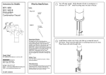
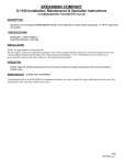
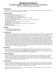
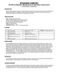
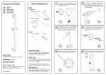
SEF-2001
SEF-2001-8
EYESAVER ®
Combination Faucet Spout
Tube
Cutter
Crescent
Wrench
Basin
Wrench
Flat Head
Screwdriver
The supply line for this unit shall provide an
uninterruptible supply of flushing fluid at a minimum
of 30 psi flowing pressure. If shut off valves are
installed in the supply line of the eyewash, provisions
shall be made to prevent unauthorized shut off.
ANSI Z358.1 requires that all emergency equipment
shall be tested weekly to verify proper operation and
inspected annually to assure conformance with
ANSI Z358.1 requirements. Be sure to read
instructions thoroughly before beginning installation.
Do not overtighten any connections or damage may
occur.
Cover your drain to prevent loss of parts. Always
wear eye protection.
®
Keep the EYESAVER faucet spout looking new by
cleaning it periodically with a soft cloth. Avoid
abrasive cleaners, steel wool, and harsh chemicals
as these will dull the finish and void your warranty.
92-SEF-2001-R1
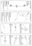
Turn off water supplies. Loosen and screw down the Spout Shank Nut (1).
Unscrew Tee Nut (2) from Spout Shank. Remove Shank Nut (1), mounting
hardware, and then remove Spout from counter top.
1
2
2
Using a Tube Cutter, cut the copper tubing between each End Body and
the Tee Assembly. Remove and discard remaining copper tube and
Capture Nuts from End Bodies. Remove COLD supply line from wall
stop and COLD End Body.
3
With Spout fully removed, verify diameter of hole in counter top is a
minimum of 1-1/4”. Install mounting studs into base of Spout.
5
From beneath countertop, install Rubber Mounting Washer (1), Brass
Mounting Washer (2) and Brass Mounting Nuts (3). Align Spout square
to sink and tighten Mounting Nuts (3).
1
2
3
4
Install Bottom Washer over hoses and slide up to meet the base of
the Spout. Place hoses through hole in countertop/sink one at a time.
Lower Spout Assembly through hole.
6
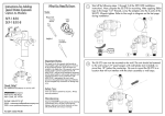
Retrieve the 6” long hose with a BLUE stripe from the box and connect
one end to the COLD supply valve. Wrench tighten.
COLD
7
Locate the Supply Tee with check valves installed. Connect remaining
end of hose to the port with no markings. Wrench tighten.
8
Locate the hose labeled “EYEWASH” that is pre-installed in the base of
the SEF-2001. Connect this hose to the “E” port of the Tee with check
valves. Wrench tighten.
9
10
Retrieve supplied hose with a 3/8” fitting on one end, and a 1/2”
fitting on the other. Connect 3/8” fitting end to the “F” port of the
Tee with check valves. Wrench tighten.
Connect the remaining end of the hose (with 1/2” fitting) to the
bottom port of the COLD End Body. Wrench tighten.
11
Retrieve the Supply Tee with no check valves. Connect the “F” port of
the Supply Tee to the remaining hose pre-installed in the base of the
SEF-2001. Wrench tighten.
13
Connect one end of the remaining hose to the blank port of the
Supply Tee with no check valves. Connect the remaining end to the
3/8” port of the COLD End Body. Wrench tighten.
12
Retrieve the two (2) remaining supplied hoses. Take the first hose and
connect one end to the “E” port of the Supply Tee with no check
valves. Connect the remaining end to the 3/8” port of the HOT End
Body. Wrench tighten.
14
NOTE: Before testing, you must remove tape from Eyewash Caps.
Turn on water supplies and check for leaks. Activate Eyewash by
lifting activation handle and check for proper function using the
chart at the the end of this document.
15
Turn on HOT and COLD handles of Faucet and allow water to run
for one minute to flush any debris from Faucet. Install the Aerator
with the supplied Aerator Wrench.
16
The spout was designed to swivel from left to right. If a
non-swivel Spout is preferred, remove Top Cover from Body.
Remove allen head Set Screw from position (1) as seen below.
Center the Spout between the handles and install the previously
removed Set Screw into position (2) and tighten (DO NOT
OVERTIGHTEN). Replace Cap.
1
2
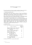
Eyewash Flow Data
A
SEF-2001
SEF-2001-8
FLOWING
PRESSURE
FLOW RATE
PLUME
DISTANCE "A"
psi
bar
gpm
L/min
in.
30
2.07
2.14
8.1
40
2.76
2.25
50
3.45
60
FLOWING
PRESSURE
FLOW RATE
PLUME
DISTANCE "A"
cm.
psi
bar
gpm
L/min
in.
cm.
12
30.5
30
2.07
2.15
8.1
17
43.2
8.5
13
33.0
40
2.76
2.24
8.5
18
45.7
2.49
9.4
15
38.1
50
3.45
2.47
9.3
20
50.8
4.14
2.70
10.2
18
45.7
60
4.14
2.71
10.3
23
58.4
70
4.83
2.95
11.2
21
53.3
70
4.83
2.95
11.2
27
68.6
80
5.52
3.09
11.7
24
61.0
80
5.52
3.13
11.8
29
73.7
NOTE: If plume heights are low, check to ensure that your Supply Valves
are fully open. If there is a noticeable height difference between the two
plumes, remove the Aerators and Flow Controls and remove any debris
that would inhibit the flow of water.
ROUGH-IN MEASUREMENTS
SEF-2001 SIDE VIEW (LESS HOSES)
FRONT VIEW
5-1/2"
4-1/2"
4"
4-7/8"
2-5/8"
6" MIN FROM WALL
OR OBSTRUCTION
65°
4-1/2"
8"
1-3/8” HOLES (2)
2-1/4"
1/2” COMPRESSION INLET
24” MIN - 36” MAX
COUNTERTOP HEIGHT
2" MAX. DECK HEIGHT
2-1/4"
EYEWASH HOSE
SPOUT SUPPLY
HOSE
HOT SUPPLY
5-1/4"
1-1/4" MINIMUM HOLE SIZE
2" MAX. DECK HEIGHT
19” (SEF-2001)
17” (SEF-2001-8)
(2 HOSES)
8-7/8"
12°
COLD SUPPLY
SEF-2001-8 SIDE VIEW (LESS HOSES)
7-1/2"
6” LONG HOSE
TEE WITHOUT
CHECK VALVES
TEE WITH CHECK
VALVES
REPAIR PARTS
G05-0872-PC
1.5 GPM FAUCET AERATOR
RPG05-0908
EYEWASH AERATORS, FLOW CONTROL ADAPTERS, ADAPTER WASHERS, AND FLOW CONTROLS
RPG04-0409
EYEWASH HANDLE WITH YELLOW TEXT AND SET SCREW
RPG05-0910
UPPER EYEWASH COVER WITH FLIP CAPS
RPG05-0909
EYEWASH CARTRIDGE
RPG49-0009
SPOUT QUAD RINGS (3) AND FRICTION WASHER (2)
G01-0053
MOUNTING HARDWARE GROUP
RPG41-0120
SPOUT INDEX BUTTON
G05-0627
CHECK VALVE (FOR TEE)
6-7/8"
6" MIN FROM WALL
OR OBSTRUCTION
65°
10"
12°
10-7/8"
7-1/4"
2-1/4"
2" MAX DECK HEIGHT
NOTE: UNLESS OTHERWISE SPECIFIED, ALL INLETS ARE 3/8”
COMPRESSION WITH FEMALE THREADS. UNLESS OTHERWISE SPECIFIED,
ALL DIMENSIONS ARE IN INCHES AND ARE SUBJECT TO CHANGE
WITHOUT NOTICE.