1
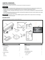
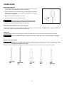
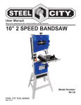
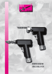
User Manual Read and understand this manual before using machine. 13” VS DRILL PRESS Model Number 20130VS STEEL CITY TOOL WORKS VER. 10.13 TABLE OF CONTENTS Product Specifications ............................................................................................................................................................................... 3 Safety ......................................................................................................................................................................................................... 4 Accessories and Attachments .................................................................................................................................................................... 5 Carton Contents ......................................................................................................................................................................................... 6 Assembly ................................................................................................................................................................................................... 7 Adjustment ................................................................................................................................................................................................. 8 Operations ................................................................................................................................................................................................. 9 Maintenance ............................................................................................................................................................................................. 10 Troubleshooting Guide ............................................................................................................................................................................. 11 2 WARNING: Some dust created by power sanding, sawing, grinding, drilling and other construction activities contain chemicals known to cause cancer, birth defects or other reproductive harm. Some examples of these chemicals are: Lead from lead-based paints. Crystalline silica from bricks, cement and other masonry products. Arsenic and chromium from chemically treated lumber. Your risk from these exposures varies, depending on how often you do this type of work. To reduce your exposure to these chemicals, work in a well-ventilated area and work with approved safety equipment such as dust masks that are specially designed to filter out microscopic particles. PRODUCT SPECIFICATIONS (Please choose proper power source, voltage and frequency that are shown in the label for your drill press.) MODEL 20130VS MOTOR 3/4 HP CHUCK 5/8” JT3 SPINDLE TRAVEL 3.25” / 82mm SPINDLE TAPER MT2 SPEED CHANGE Digital Variable SPEED 480-2400 RPM SWING 12.75” / 324mm TABLE SIZE 11.25” sq. / 290mm sq. BASE SIZE 16.25” x 9.5” / 420 x 250mm COLUMN 2 7/8” / 72mm CARTON SIZE 32” x 20” x 11.5” / 802 x 500 x 290mm WEIGHT (GW/NW) 108lb., 49kg / 104lb., 47kg WARNING: To avoid electrical hazards, fire hazards, or damage to the tool, use proper circuit protection. Use a separate electrical circuit for your tools. To avoid shock or fire, replace power cord immediately if it is worn, cut or damaged in any way. 3 GENERAL SAFETY RULES WARNING: Failure to follow these rules may result in serious personal injury. 1. For your own safety, read the instruction manual before operating the machine. Learning the machine’s application, limitations, and specific hazards will greatly minimize the possibility of accidents and injury. 2. Wear eye and hearing protection and always use safety glasses. Everyday eyeglasses are not safety glasses. Use certified safety equipment. Eye protection equipment should comply with ANSI Z87.1 standards. Hearing equipment should comply with ANSI S3.19 standards. 3. Wear proper apparel. Do not wear loose clothing, gloves, neckties, rings, bracelets, or other jewelry which may get caught in moving parts. Nonslip protective footwear is recommended. Wear protective hair covering to contain long hair. 4. Do not use the machine in a dangerous environment. The use of power tools in damp or wet locations or in rain can cause shock or electrocution. Keep your work area well-lit to prevent tripping or placing arms, hands, and fingers in danger. 5. Do not operate electric tools near flammable liquids or in gaseous or explosive atmospheres. Motors and switches in these tools may spark and ignite fumes. 6. Maintain all tools and machines in peak condition. Keep tools sharp and clean for best and safest performance. Follow instructions for lubricating and changing accessories. Poorly maintained tools and machines can further damage the tool or machine and/or cause injury. 7. Check for damaged parts. Before using the machine, check for any damaged parts. Check for alignment of moving parts, binding of moving parts, breakage of parts, and any other conditions that may affect its operation. A guard or any other part that is damaged should be properly repaired or replaced with SCTW or factory authorized replacement parts. Damaged parts can cause further damage to the machine and/or injury. 8. Keep the work area clean. Cluttered areas and benches invite accidents. 9. Keep children and visitors away. Your shop is a potentially dangerous environment. Children and visitors can be injured. 10. Reduce the risk of unintentional starting. Make sure that the switch is in the “OFF” position before plugging in the power cord. In the event of a power failure, move the switch to the “OFF” position. An accidental start-up can cause injury. Do not touch the plug’s metal prongs when unplugging or plugging in the cord. 11. Use the guards. Check to see that all safety devices are in place, secured, and working correctly to prevent injury. 12. Remove adjusting keys and wrenches before starting the machine. Tools, scrap pieces, and other debris can be thrown at high speed, causing injury. 13. Use the right machine. Don’t force a machine or an attachment to do a job for which it was not designed. Damage to the machine and/or injury may result. 14. Use recommended accessories. The use of accessories and attachments not recommended by SCTW may cause damage to the machine or injury to the user. 4 15. Use the proper extension cord. Make sure your extension cord is in good condition. When using an extension cord, be sure to use one heavy enough to carry the current your product will draw. An undersized cord will cause a drop in line voltage, resulting in loss of power and overheating. See the Extension Cord Chart for the correct size depending on the cord length and nameplate ampere rating. If in doubt, use the next heavier gauge. The smaller the gauge number, the heavier the cord. 16. Secure the workpiece. Use clamps or a vise to hold the workpiece when practical. Loss of control of a workpiece can cause injury. 17. Feed the workpiece against the direction of the rotation of the blade, cutter, or abrasive surface. Feeding it from the other direction will cause the workpiece to be thrown out at high speed. 18. Don’t force the workpiece on the machine. Damage to the machine and/or injury may result. 19. Don’t overreach. Loss of balance can make you fall into a working machine, causing injury. 20. Never stand on the machine. Injury could occur if the tool tips, or if you accidentally contact the cutting tool. 21. Never leave the machine running unattended. Turn the power off. Don’t leave the machine until it comes to a complete stop. A child or visitor could be injured. 22. Turn the machine “OFF”, and disconnect the machine from the power source before installing or removing accessories, changing cutters, adjusting or changing set-ups. When making repairs, be sure to lock the start switch in the “OFF” position. An accidental start-up can cause injury. 23. Make your workshop childproof with padlocks, master switches, or by removing starter keys. The accidental start-up of a machine by a child or visitor could cause injury. 24. Stay alert, watch what you are doing, and use common sense. Do not use the machine when you are tired or under the influence of drugs, alcohol, or medication. A moment of inattention while operating power tools may result in injury. 25. WARNING: Use of this tool can generate and disperse dust or other airborne particles, including wood dust, crystalline silica dust and asbestos dust. Direct particles away from face and body. Always operate tool in well ventilated area and provide for proper dust removal. Use dust collection system wherever possible. Exposure to the dust may cause serious and permanent respiratory or other injury, including silicosis (a serious lung disease), cancer, and death. Avoid breathing the dust, and avoid prolonged contact with dust. Allowing dust to get into your mouth or eyes, or lay on your skin may promote absorption of harmful material. Always use properly fitting NIOSH/OSHA approved respiratory protection appropriate for the dust exposure, and wash exposed areas with soap and water. ELECTRICAL REQUIREMENTS POWER SUPPLY AND MOTOR SPECIFICATIONS WARNING: To avoid electrical hazards, fire hazards, or damage to the tool, use proper circuit protection. Use a separate electrical circuit for your tools. To avoid shock or fire, if power cord is worn or cut or damaged in any way, have it replaced immediately. GROUNDING INSTRUCTIONS WARNING: This tool MUST be grounded while in use to protect the operator from electrical shock. IN THE EVENT OF A MALFUNCTION OR BREAKDOWN, grounding provides a path of least resistance for electric currents and reduces the risk of an electric shock. This tool is equipped with an electric cord that has an equipment-grounding conductor and a grounding plug. The plug MUST be plugged into a matching receptacle that is properly installed and grounded in accordance with ALL local codes and ordinances. DO NOT MODIFY THE PLUG PROVIDED. If it will not fit the receptacle, have the proper receptacle installed by a qualified electrician. IMPROPER CONNECTION of the equipment-grounding conductor can result in a risk of an electric shock. The conductor with green insulation (with or without yellow stripes) is the equipment-grounding conductor. If repair or replacement of an electric cord or plug is necessary, DO NOT connect the equipment-grounding conductor to a live terminal. CHECK with a qualified electrician or service person if you do not completely understand the grounding instructions, or if you are not sure the tool is properly grounded. WARNING: Improper connection of equipment-grounding conductor can result in the risk of an electrical shock. Equipment should be grounded while in use to protect user from an electrical shock. Check with a qualified electrician if you do not understand grounding instructions or if you are in doubt as to whether the tool is properly grounded. This tool is equipped with an approved cord and a 3-prong grounding type plug for your protection against shock hazards. Grounding plug should be plugged directly into a properly installed and grounded 3-type receptacle, as above. DO NOT REMOVE or alter the grounding prong in any manner. In the event of a malfunction or breakdown, grounding provides a path of least resistance for electrical shock. WARNING: This machine is for indoor use only. DO NOT expose to rain or use in damp locations. GUIDELINES FOR EXTENSION CORDS USE PROPER EXTENSION CORD. Make sure your extension cord is in good condition. When using an extension cord, be sure to use one heavy enough to carry the current your product will draw. An undersized cord will cause a drop in line voltage, resulting in loss of power and overheating. BE SURE YOUR EXTENSION CORD IS PROPERLY WIRED and in good condition. Always replace a damaged extension cord or have it repaired by a qualified person before using it. Protect your extension cords from sharp objects, excessive heat and damp or wet areas. ACCESSORIES AND ATTACHMENTS RECOMMENDED ACCESSORIES WARNING: To avoid injury: USE ONLY accessories recommended for this drill press. )2//2:instructions that accompany accessories. Use of improper accessories may cause hazards. 86(21/< accessories designed for this drill press to avoid injury from thrown broken parts or workpieces. '2127 use any accessory unless you have completely read the instruction or user manual for that accessory. 5 CARTON CONTENTS UNPACKING AND CHECKING CONTENTS Carefully unpack the drill press and all its parts. Compare against the illustration drawing below. WARNING: To avoid injury from unexpected start, DO NOT plug the power cord into a power source receptacle during unpacking and assembly. This cord must remain unplugged whenever you are assembling or adjusting the drill press. If any part is missing or damaged, DO NOT plug the drill press in until the missing or damaged part is replaced and assembly is complete. To protect the drill press from moisture, a protective coating has been applied to the machine surfaces. Remove this coating with a soft cloth moistened with kerosene. WARNING: To avoid fire or toxic reaction, NEVER use gasoline, naphtha, acetone, lacquer thinner or similar highly volatile solvents to clean the drill press. MACHINE PARTS Unpack carton and check your machine to see parts listed below: 2 1 3 . 4 7 9 10 8 6 5 PARTS 1. Head assembly QTY PARTS 1 QTY 4. Fence accessory 2. Accessory bag # 1 5. Base 1 Feed handles 3 6. Table 1 Chuck tool 1 7. User manual 1 Hex wrench 4 8. Table support 1 Hex socket bolt 4 9. Table adjustment handle 1 3. Accessory bag #2 10. Column assembly 1 Arbor 1 Column collar 1 Chuck 1 Gear rack 1 Chuck key 1 6 ASSEMBLY 1. Install column to base. 2. Install table assembly. 3. Install table adjustment handle. 4. Install head assembly. 5. Install feed handles. 6. Install the handwheel, tighten the set screw. Carefully lift the head above the column and slide it onto the column. Make sure the head slides down the column as far as possible. Align the head with the base. Using the hex wrench, tighten the head lock set screws. Fig.1 Fig.2 7. Install the chuck. WARNING: Before any assembly of the chuck and arbor to the drill press head, clean all matting surfaces with a non-petroleum based product, such as alcohol or lacquer thinner. Any oil or grease used in the packing of these parts must be removed; otherwise the chuck may come loose during operation. 3XVKWKHDUERURQWRWKHVSLQGOH(SEE FIG.1). 3XVKWKHFKXFNRQWRWKHDUERU(SEE FIG.2). 8VLQJDZRRGPDOOHWILUPO\WDSWKHFKXFNXSZDUGLQWRSRVLWLRQRQWKHVSLQGOHVKDIW(SEE FIG.2). 7 ADJUSTMENT A B TABLE ADJUSTMENT A. Tilting adjustment: Loosen the lock bolt, then swing the table to appropriate position and re-tighten the lock bolt. B. Swing 360°: Loosen the table bracket’s locking handle, then swing the table to the appropriate position and re-tighten the locking handle. DIGITAL DEPTH DISPLAY 1 FEED DEPTH ADJUSTMENT Turn the depth scale ring to the needed depth, then lock the scale ring in place with the depth knob (1). The drill bit will stop after traveling the selected distance on the depth scale. Otherwise you can read the depth from the digital depth display. DIGITAL SPEED DISPLAY SPRING CAP SCREW SPEED HANDWHEEL SPEED ADJUSTMENT QUILL SPRING ADJUSTMENT This drill press can change speed by rotating the handwheel. You can read the speed from the digital speed display. The quill return spring may need adjustment if the tension causes the quill to return too rapidly or too slowly. Take out the screw and carefully turn the spring cap counterclockwise, then attach the screw to the other hole of the spring cap. WARNING: Change the speed only while the machine is running! 8 OPERATIONS INSTALLING A DRILL BIT 1. With the switch “OFF”, open the chuck jaws (1) using the chuck key (2). Turn the chuck key counterclockwise to open the chuck jaws (1). 2. Insert the drill bit (3) into the chuck far enough to obtain maximum gripping by the jaws, but not far enough to touch the spiral grooves (flutes) of the drill bit when the jaws are tightened. 3. Make sure that the drill is centered in the chuck. 4. Turn the chuck key clockwise to tighten the jaws. WARNING: To avoid injury or accident by the chuck key ejecting forcibly from the chuck when the power is turned ON, always recheck and remove the chuck key before turning the power ON. POSITIONING WORKPIECE (accessory fence supplied) To prevent the workpiece or back-up material from being torn from your hands while drilling, you MUST position it against the LEFT side of the column. Failure to do this could result in personal injury. USING VISE For small workpieces that cannot be clamped to the table, use a drill press vise. The vise must be clamped or bolted to the table. WARNING: The drill vise MUST be clamped or bolted to the table to avoid injury from a spinning workpiece, damaged vise or bit parts. CORRECT DRILLING SPEEDS WARNING: Make sure to only adjust speeds with the crank handle while the machine is running, and adjust to the speed chart below for the bit you are using. Use the recommended speed for the drill bit and workpiece. The drill bits that can be used is shown in the following picture: 9 RECOMMENDED OPERATING SPEEDS (RPMS) ACCESSORY Material SOFTWOOD HARDWOOD ACRYLIC BRASS ALUMINUM STEEL TWIST DRILL BITS 1/16-3/16 (1.5 - 5mm) 3000 3000 2500 3000 3000 3000 1/4-3/8 (6-10mm) 3000 1500 2000 1200 2500 1000 7/16-5/8 (11-16mm) 1500 750 1500 750 1500 600 11/16-1 (17-27mm) 750 500 NR 400 1000 NR 1/8 1800 1200 1500 NR NR NR 1/4 1800 1000 1500 NR NR NR 3/8 1800 750 1500 NR NR NR 1/2 1800 750 1000 NR NR NR 5/8 1800 500 750 NR NR NR 3/4 1400 250 750 NR NR NR 7/8 1200 250 500 NR NR NR 1 1000 250 200 NR NR NR 1/4-3/8 2400 700 250 NR NR NR 1/2-5/8 2400 500 250 NR NR NR 3/4-1 1500 500 250 NR NR NR 11/8 - 11/4 1000 250 250 NR NR NR 13/8-2 500 250 NR NR NR NR 1/4-1/2 2000 1500 NR NR NR NR 5/8-11/2 1750 1500 NR NR NR NR 11/8 -11/2 1500 1000 NR NR NR NR 1800 500 NR NR NR BRAD- POINT BITS FORSTNER BITS SPADE BITS SPADE BITS WITH SPURS 3/8-1 NR 2000 NR-Not Recommended MAINTENANCE MAINTAINING YOUR DRILL PRESS WARNING: For your own safety, turn the switch OFF and remove the plug from the power source outlet before maintaining or lubricating your drill press. Frequently blow out using an air compressor or dust vacuum, any dust that accumulates inside the motor. A coat of paste wax applied to the table and column will help keep the surface clean and help avoid rust. To avoid shock or fire hazard, if the power cord is worn or cut in any way, have it replaced immediately. LUBRICATION All of the drill press ball bearings are packed with grease at the factory. They require no further lubrication. Lower spindle to maximum depth and oil moderately once every three months. 10 TROUBLESHOOTING CHART Symptom Possible Cause(s) Corrective Action Noisy operation. 1. Incorrect belt tension. 1. Adjust tension. 2. Dry spindle. 2. Lubricate spindle. 3. Loose spindle. 3. Tighten pulley nut. 4. Loose motor pulley. 4. Tighten set screw in pulley. 1. Incorrect speed. 1. Change speed. 2. Chips not coming out of hole. 2. Retract bit frequently to clear chips. 3. Dull bit. 3. Sharpen or replace bit. 1. Bent bit. 1. Replace bit. 2. Bit not properly installed in chuck. 2. Install bit properly. 3. Chuck not properly installed. 3. Install chuck properly. 4. Worn spindle bearings. 4. Replace bearings. 1. Workpiece pinching bit or excessive feed pressure. 1. Support or clamp workpiece, decrease feed pressure. 2. Improper belt tension. 2. Adjust tension. Bit burns or smokes. Excessive drill bit run out or wobble. Drill bit binds in workpiece. Workpiece torn loose from hand. 1. Supported or clamped improperly. 1. Support or clamp workpiece properly. 11 STEEL CITY TOOL WORKS www.steelcitytoolworks.com 1-877-SC4-TOOL (1-877-724-8665) NOTES www.steelcitytoolworks.com Steel City Tool Works, LLC Bolingbrook, IL. USA 60440 Tech Service: 1.877.724.8665