Download 10” 2 SPEED BANDSAW
Transcript
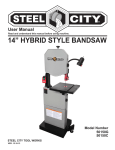
User Manual Read and understand this manual before using machine. 10” 2 SPEED BANDSAW Model Number 50110 STEEL CITY TOOL WORKS VER. 10.13 TABLE OF CONTENTS Product Specifications.......................................................................................................................................................... 3 Safety................................................................................................................................................................................... 4 Accessories and Attachments.............................................................................................................................................. 5 Carton Contents................................................................................................................................................................... 6 Installation............................................................................................................................................................................ 7 Adjustment ........................................................................................................................................................................... 8 Operations ..........................................................................................................................................................................11 Maintenance.......................................................................................................................................................................14 2 PRODUCT SPECIFICATIONS ATTENTION: Please choose proper power source, voltage and frequency that are shown in the label for your bandsaw. MODEL 50110 MOTOR POWER 1/2 HP THROAT WIDTH 9.5” / 245mm 6” / 150mm CUTTING CAPACITY CUTTING SPEED LOW 15’/min / 400m/min HIGH 31’/min / 800m/min BLADE SIZE 72”/1826mm (length) x 3/8”/6-12.5mm (width) BLADE RANGE 1/8”-1/2” TABLE SIZE 14”/360mm x 12.5”/320mm CARTON SIZE 40” x 18” x 15” / 1015 x 450 x 380mm WEIGHT (GW/NW) 86lb./39kg / 82lb./37kg 3 GENERAL SAFETY RULES WARNING: Failure to follow these rules may result in serious personal injury. 1. For your own safety, read the instruction manual before operating the machine. Learning the machine’s application, limitations, and specific hazards will greatly minimize the possibility of accidents and injury. 2. Wear eye and hearing protection and always use safety glasses. Everyday eyeglasses are not safety glasses. Use certified safety equipment. Eye protection equipment should comply with ANSI Z87.1 standards. Hearing equipment should comply with ANSI S3.19 standards. 3. Wear proper apparel. Do not wear loose clothing, gloves, neckties, rings, bracelets, or other jewelry which may get caught in moving parts. Nonslip protective footwear is recommended. Wear protective hair covering to contain long hair. 4. Do not use the machine in a dangerous environment. The use of power tools in damp or wet locations or in rain can cause shock or electrocution. Keep your work area well-lit to prevent tripping or placing arms, hands, and fingers in danger. 5. Do not operate electric tools near flammable liquids or in gaseous or explosive atmospheres. Motors and switches in these tools may spark and ignite fumes. 6. Maintain all tools and machines in peak condition. Keep tools sharp and clean for best and safest performance. Follow instructions for lubricating and changing accessories. Poorly maintained tools and machines can further damage the tool or machine and/or cause injury. 7. Check for damaged parts. Before using the machine, check for any damaged parts. Check for alignment of moving parts, binding of moving parts, breakage of parts, and any other conditions that may affect its operation. A guard or any other part that is damaged should be properly repaired or replaced with SCTW or factory authorized replacement parts. Damaged parts can cause further damage to the machine and/or injury. 8. Keep the work area clean. Cluttered areas and benches invite accidents. 9. Keep children and visitors away. Your shop is a potentially dangerous environment. Children and visitors can be injured. 10. Reduce the risk of unintentional starting. Make sure that the switch is in the “OFF” position before plugging in the power cord. In the event of a power failure, move the switch to the “OFF” position. An accidental start-up can cause injury. Do not touch the plug’s metal prongs when unplugging or plugging in the cord. 11. Use the guards. Check to see that all safety devices are in place, secured, and working correctly to prevent injury. 12. Remove adjusting keys and wrenches before starting the machine. Tools, scrap pieces, and other debris can be thrown at high speed, causing injury. 13. Use the right machine. Don’t force a machine or an attachment to do a job for which it was not designed. Damage to the machine and/or injury may result. 14. Use recommended accessories. The use of accessories and attachments not recommended by SCTW may cause damage to the machine or injury to the user. 4 15. Use the proper extension cord. Make sure your extension cord is in good condition. When using an extension cord, be sure to use one heavy enough to carry the current your product will draw. An undersized cord will cause a drop in line voltage, resulting in loss of power and overheating. See the Extension Cord Chart for the correct size depending on the cord length and nameplate ampere rating. If in doubt, use the next heavier gauge. The smaller the gauge number, the heavier the cord. 16. Secure the workpiece. Use clamps or a vise to hold the workpiece when practical. Loss of control of a workpiece can cause injury. 17. Feed the workpiece against the direction of the rotation of the blade, cutter, or abrasive surface. Feeding it from the other direction will cause the workpiece to be thrown out at high speed. 18. Don’t force the workpiece on the machine. Damage to the machine and/or injury may result. 19. Don’t overreach. Loss of balance can make you fall into a working machine, causing injury. 20. Never stand on the machine. Injury could occur if the tool tips, or if you accidentally contact the cutting tool. 21. Never leave the machine running unattended. Turn the power off. Don’t leave the machine until it comes to a complete stop. A child or visitor could be injured. 22. Turn the machine “OFF”, and disconnect the machine from the power source before installing or removing accessories, changing cutters, adjusting or changing set-ups. When making repairs, be sure to lock the start switch in the “OFF” position. An accidental start-up can cause injury. 23. Make your workshop childproof with padlocks, master switches, or by removing starter keys. The accidental start-up of a machine by a child or visitor could cause injury. 24. Stay alert, watch what you are doing, and use common sense. Do not use the machine when you are tired or under the influence of drugs, alcohol, or medication. A moment of inattention while operating power tools may result in injury. 25. WARNING: Use of this tool can generate and disperse dust or other airborne particles, including wood dust, crystalline silica dust and asbestos dust. Direct particles away from face and body. Always operate tool in well ventilated area and provide for proper dust removal. Use dust collection system wherever possible. Exposure to the dust may cause serious and permanent respiratory or other injury, including silicosis (a serious lung disease), cancer, and death. Avoid breathing the dust, and avoid prolonged contact with dust. Allowing dust to get into your mouth or eyes, or lay on your skin may promote absorption of harmful material. Always use properly fitting NIOSH/OSHA approved respiratory protection appropriate for the dust exposure, and wash exposed areas with soap and water. ELECTRICAL REQUIREMENTS POWER SUPPLY AND MOTOR SPECIFICATIONS WARNING: To avoid electrical hazards, fire hazards, or damage to the tool, use proper circuit protection. Use a separate electrical circuit for your tools. To avoid shock or fire, if power cord is worn or cut or damaged in any way, have it replaced immediately. GROUNDING INSTRUCTIONS WARNING: This tool MUST be grounded while in use to protect the operator from electrical shock. IN THE EVENT OF A MALFUNCTION OR BREAKDOWN, grounding provides a path of least resistance for electric currents and reduces the risk of an electric shock. This tool is equipped with an electric cord that has an equipment-grounding conductor and a grounding plug. The plug MUST be plugged into a matching receptacle that is properly installed and grounded in accordance with ALL local codes and ordinances. DO NOT MODIFY THE PLUG PROVIDED. If it will not fit the receptacle, have the proper receptacle installed by a qualified electrician. IMPROPER CONNECTION of the equipment-grounding conductor can result in a risk of an electric shock. The conductor with green insulation (with or without yellow stripes) is the equipment-grounding conductor. If repair or replacement of an electric cord or plug is necessary, DO NOT connect the equipment-grounding conductor to a live terminal. CHECK with a qualified electrician or service person if you do not completely understand the grounding instructions, or if you are not sure the tool is properly grounded. WARNING: Improper connection of equipment-grounding conductor can result in the risk of an electrical shock. Equipment should be grounded while in use to protect user from an electrical shock. Check with a qualified electrician if you do not understand grounding instructions or if you are in doubt as to whether the tool is properly grounded. This tool is equipped with an approved cord and a 3-prong grounding type plug for your protection against shock hazards. Grounding plug should be plugged directly into a properly installed and grounded 3-type receptacle, as above. DO NOT REMOVE or alter the grounding prong in any manner. In the event of a malfunction or breakdown, grounding provides a path of least resistance for electrical shock. WARNING: This machine is for indoor use only. DO NOT expose to rain or use in damp locations. GUIDELINES FOR EXTENSION CORDS USE PROPER EXTENSION CORD. Make sure your extension cord is in good condition. When using an extension cord, be sure to use one heavy enough to carry the current your product will draw. An undersized cord will cause a drop in line voltage, resulting in loss of power and overheating. BE SURE YOUR EXTENSION CORD IS PROPERLY WIRED and in good condition. Always replace a damaged extension cord or have it repaired by a qualified person before using it. Protect your extension cords from sharp objects, excessive heat and damp or wet areas. ACCESSORIES AND ATTACHMENTS RECOMMENDED ACCESSORIES WARNING: To avoid injury: USE ONLY accessories recommended for this bandsaw. )2//2:instructions that accompany accessories. Use of improper accessories may cause hazards. 86(21/< accessories designed for this drill press to avoid injury from thrown broken parts or workpieces. '2127 use any accessory unless you have completely read the instruction or user manual for that accessory. 5 CARTON CONTENTS UNPACKING AND CHECKING CONTENTS Carefully unpack the bandsaw and all its parts. Compare against the illustration drawing below. WARNING: To avoid injury from unexpected starting, do not plug the power cord into a power source receptacle during unpacking and assembly. This cord must remain unplugged whenever you are assembling or adjusting the bandsaw. If any part is missing or damaged, do not plug the bandsaw in until the missing or damaged part is replaced, and assembly is complete. MACHINE PARTS Unpack carton and check your machine to see parts listed below: 1 3 4 2 5 6 8 7 10 9 9 11 PARTS QTY PARTS QTY 1. Bandsaw 1 Hardware bag (not shown) 2. Guide rail 1 M6x10 socket head bolts 8 3. Table with insert 1 6mm flat washers 8 4. Rip fence 1 M6x12 carriage bolts 8 5. Short brace 2 6mm flat washers 8 6. Leg 4 M6 hex nut 8 7. Long brace 2 8. Miter gauge 1 9. Knob 4 10. Push stick 1 * Tools and hook with hex nut bag (not shown) 6 1 INSTALLATION 1. Securing the bandsaw stand. Put down the machine on an angle according to the figure on the right. Attach legs to bandsaw by using M6x10 socket bolts and 6mm flat washers. Fix short braces and long braces to legs by using M6x12 carriage bolts, 6mm flat washers and M6 hex nuts. DO NOT TIGHTEN THE NUT. Stand the bandsaw on a level ground, then tighten all bolts and nuts. M6X10 socket head bolts and 6mm flat washers M6X12 carriage bolts, 6mm flat washers and M6 hex nut Tighten the nuts 2. Assembling table. After attaching the stand, assemble the table to bandsaw by using M6x10 bolts. Make sure the saw blade is in the center of the table’s insert slot. 3. Installing the guide rail. Secure the guide rail with four knobs to the table. 4. Secure the hook with hex nut to the frame. Place accessory tools in assembly. Guide rail Hook M6X10 hex head bolts and 6mm flat washers. NOTE: Already mounted on the table. Accessory tools assembly Guide rail locking knob Push stick Rip fence 5. Set rip fence onto the table. Set push stick onto the hook. 7 ADJUSTMENT WARNING: Always be sure that the tool is switched OFF and unplugged before any adjustments. 1. Tilting table. • Loosen the locking handle, then turn the table to adjust it to the desired angle. • Use the angle indicator scale to find the desired angle. • Re-tighten the locking handle to secure the table. Locking handle 2. Aligning the saw blade. • If the saw blade does not run in the center of the rubber tire, the tracking needs to be corrected by adjusting the tilt of the upper band saw wheel. • Open the upper and lower cover. • Loosen the tracking lock knob, then manually rotate the upper wheel while taking care not to touch the blade. • Turn setting knob clockwise or counterclockwise until the saw blade tracks are centered on the rubber tire. • After adjusting, re-tighten the tracking lock knob and close the cover. Upper cover Tracking set knob Saw blade tension knob Lower cover Tracking lock knob 3. Adjusting the blade tension. WARNING: Too much tension can cause the band/blade to break. Too little tension can cause the driven bandsaw wheel to slip and the saw blade to stop. • Raise upper blade guide fully. Taking the blade width into consideration, turn the knob to adjust tension. • Check tension by pushing with a finger halfway between table and upper guide against the side blade (the blade should flex no more than 5/64” / 2mm). • Turning the tension knob clockwise increases the blade tension. • Turning the tension knob counterclockwise reduces the blade tension. 8 4. Upper blade guide adjustment. The height of blade guide needs to be adjusted prior to every cutting/operation, to accommodate the height of workpiece (the upper blade guide should be set approximately 1/8” / 3mm above the workpiece). Set the upper blade guide with the adjusting knob to the desired height by loosening the locking knob. After adjustment, be sure to tighten the lock knob. Loosen the knob (A) and adjust the bearing holder so that the guide bearing is positioned 3/64” / 1mm or 5/64“ / 2mm from bottom of blade. Re-tighten the knob (A). Loosen the knob (B) and adjust the thrust bearing to a position of 1/32” / 0.5mm from rear of blade. Re-tighten the knob (B). Loosen the bolt (C) and adjust the guide bearing to a position 1/32” / 0.5mm away from blade. Re-tighten the bolt (C). Locking knob Adjusting knob Upper blade guide A B C 5. Align the lower blade guide. The lower blade guide needs to be readjusted after every bandsaw blade change or tracking adjustment. Loosen the socket bolt (D) and move the entire lower blade guide. Adjust the guide bearing to a position of 3/64” / 1mm or 5/64“ / 2mm from the bottom of the blade. Re-tighten the socket bolt (D). Loosen the bolt (E) and adjust the thrust bearing to a position of 1/32” / 0.5mm from rear of blade. Re-tighten the bolt (E). Loosen the bolt (F) and adjust the guide bearing to a position 1/32” / 0.5mm away from blade. Re-tighten the bolt (F). E F D 9 6. Cutting speed adjustment. Open the lower cover. Slacken the driving belt by turning the knob clockwise. Put the driving belt on required pulley of the driving wheel (lower bandsaw wheel) and the corresponding motor pulley. Adjusting belt tension. If necessary, adjust the motor position to adjust the belt tension. Loosen the motor locking bolt and turn the motor counter-clockwise to reduce the driving belt tension, turn the motor clockwise to increase the driving belt tension. Re-tighten the motor locking bolt. Half-way between the pulleys the driving belt should flex 25/64” / 10mm. Close the lower cover. MOTOR LOCKING BOLT 7. Changing the bandsaw blade. WARNING: The saw blade is dangerous. Be sure to wear gloves when handling the saw blade in situations such as removing from packaging, mounting or replacing blade. Loosen the four lock knobs for the guide rail and pull out the guide rail. Open the upper and lower covers. Set the upper blade guide to its lowest position. Loosen the saw blade tension knob until the bandsaw has slackened. Remove the bandsaw blade from the machine. Fit a fresh bandsaw and center bandsaw blade on the rubber tires of the bandsaw wheels. Tighten the saw blade tension knob. Return the guide rail to its original position. Close the upper and lower covers. Next align the saw blade, adjust the blade tension, and adjust the upper blade guide and lower blade guide. Saw blade tension knob NOTE: To prevent premature wear of the tires, release the tension on the blade when machine is not in use. Guide rail locking knob 10 OPERATIONS WARNING: To reduce the risk of personal injury, the following safety recommendations should be observed when operating the saw. DO NOT touch the saw blade when cutting. During saw operation, wear safety glasses, but DO NOT wear gloves. Cut only ONE workpiece at a time. ALWAYS hold the workpiece down on the table. DO NOT jam any workpieces. DO NOT try to slow the saw blade band down or stop it by pushing the workpiece against the saw blade from the side. When straight cutting against the fence USE a push stick. USE work support when cutting long stock, this would otherwise fall off the table on completion of cut. USE dust collector. When cutting round stock, FIRMLY secure it. Before starting work, CHECK the saw blade’s upper and lower blade guard are in proper working order. REPLACE damaged parts immediately. Assume correct work position (the bandsaw blade’s teeth must point towards the user). Take care to avoid a risk of a kickback. LED light switch Switch action. To start the tool, turn ON the main switch. To stop the tool, turn OFF the main switch. Main switch LED work light. The LED work light is built onto the long flexible goose neck giving it the ability to illuminate the work surface on both sides of the blade. Push the upper position (I) of the LED light switch for turning ON the light and the lower position (O) for OFF. Using rip fence. The rip fence can be used on both sides of the blade. When the rip fence is moved from one side of the saw blade to the other, the fence needs to reverse. Reversing the fence. Loosen and remove the two knobs (G). Take off the fence with bolts from the fence support. Assemble the fence with bolts to the other side of the fence support. Replace the two knobs (G). G 11 Clamping the rip fence. Place rip fence on the guide rail. Move the fence to a needed position. The scale indicates distance from saw blade to the fence. Tighten the lock lever to clamp the rip fence. Lock lever Fence height can be lowered when cutting thin materials. Loosen the two knobs (G). (Refer to diagram on previous page). H Slide the fence out from fence support. Rotate fence 90 as shown in the picture on the right. Insert the lock screw into the other groove of the fence. Retighten the two knobs (G). The fence can be adjusted parallel to the side of the blade by loosening the two socket bolts (H). Using miter gauge. The miter gauge is inserted into the table slot from the table front edge. Miter gauge For miter cuts, the miter gauge can be turned 60 both directions. To set a miter angle, loosen the lock handle by turning it counter-clockwise. WARNING: When cutting with miter gauge, the lock handle must be firmly tightened. Lock handle Using push stick The push stick serves as an extension of the hand and protects against accidental contact with the saw blade. The push stick must be used if the distance between the bandsaw blade and a rip fence is less than 4” / 150mm. When the push stick is not use, it can be stored on the hook provided on the bandsaw frame. Replace push stick if damaged. Push stick 12 Sawing. Set upper blade guide 1/8” / 3mm above the workpiece. Place workpiece on the table. Plug in. Start saw. Cut workpiece in a single pass. Switch OFF if no further cutting is to be done immediately afterwards. Connecting to dust collector. The bandsaw provides a dust port. It should be connected with the dust collector when sawing wood. Dust port If you do not have a dedicated bandsaw extraction, there is another way to get rid of the saw dust. Most debris, except usual dust drifts, would fall through a grate into the dust drawer. It can be easily pulled out and cleaned. Dust drawer 13 MAINTENANCE WARNING: Always be sure the tool is switched OFF and disconnect the plug from the power supply before inspection and maintenance. 1. FREQUENT INSPECTION The bandsaw should be inspected frequently. The cord, in-lead, plug and switch should be inspected for good condition. Inspect if there is any damage on the drive part. 2. CLEANING Clean out sawdust and chips from time to time. Carefully clean the blade guard and moving parts inside the bandsaw. 3. LUBRICATION To keep the bandsaw in top running condition and to assure maximum service life, oil or grease the moving parts and rotating parts from time to time. To reduce the emitted noise, always be sure that the blade is sharp and clean. 4. KEEP IN STORAGE The bandsaw should be kept in a dry, clean and non-corrosive environment. 14 STEEL CITY TOOL WORKS www.steelcitytoolworks.com 1-877-SC4-TOOL (1-877-724-8665) NOTES www.steelcitytoolworks.com Steel City Tool Works, LLC Bolingbrook, IL. USA 60440 Tech Service: 1.877.724.8665


