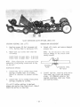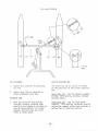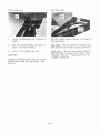
1
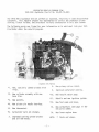
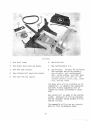
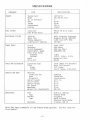
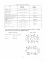
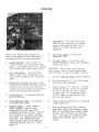
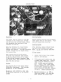
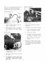
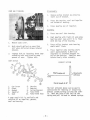
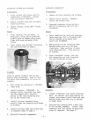
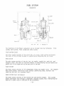
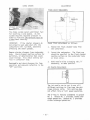
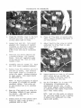
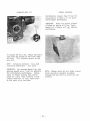
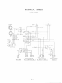
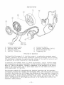
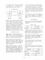
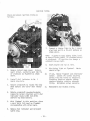
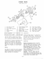
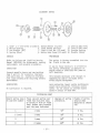
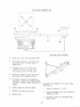
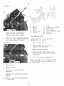
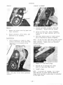
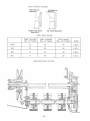
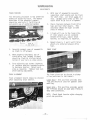
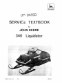
~
JOHN DEERE
uP- DATED
SERVICt:: TEXTBOOK
for
JOHN DEERE
340 Liquidator
,
.
:.
.
Litho in U.S. A.
1-6
"
..
.;"
.:"';':'~.
'.
'. '. . ?:>%~:~
.
. -:,.; '."
,~,,!,t;~~
M67054
CONTENTS
LIQU IDATOR PROGRAM 270M ......... .
SPECIFICATIONS . ..................
3
ENGINE ...........................
5
FUEL SYSTEM ............•....••... 10
ELECTRICAL SYSTEM ..•...........•• 11
POWER TRAIN . •..••..........••.... 20
SUSPENSION ..•...........• •... •.•• 26
LIQUIDATOR REBUILD PROGRAM 270M
1976 340 Liquidator (Serial No. 55,001-70,000)
The 1976 340 Liquidator did not perform as expected, re sulting in some dissatisfied
customers. This rebuild program was implemented to correct the premature piston
scoring, clutch failure, and structural failures encountered in this past season.
The following parts are listed for your information as to what went into your 1976
Liquidator under the rebuild program .
.IIIIt";;
*1.
Engine Kit Parts
8. New primary drive clutch.
New, specially cammed pistons with
rings.
9. Improved carburetor venting.
*2.
New cylinder assembly with new
bore size.
*3.
New gaskets.
*4.
New piston pin needle bearings.
*5.
New thermostat.
*6.
Carburetor main jet changes.
7.
Improved cooling system by-pass
and a 11 new hoses.
- 1 -
*10.
New rebui lt water pump.
*11.
Rebuilt and new ignition system.
*12.
New fuel pump and hoses.
13.
New carburetors (See page 11 for
new pa rts added).
14.
New lower engine hose.
NOTE:
* Pald6 not. .6 hown.
Kit Parts
1.
New front frame.
6.
New drive belt.
2.
New engine base plate and mounts.
7.
New reinforcement, R.H.
3.
New fuel pump bracket.
8.
4.
New aluminum belt guard and bracket.
5.
New snow flap and support.
Bag of parts. Includes the following:
new tensioner and spring assembly,
new ski bolts, rail reinforcement
bars, torque buttons, new brake pads,
new chain case cover seal, all new
hardware washers, bolts, nuts, cotter
pins, and pop rivets.
The above parts will be installed on all
snowmobiles. In addition the suspension
and other related components will be
checked for cracks and welded if necessary.
New coolant will be added to the cooling
system. Chaincase oil will be replaced
and the secondary torque buttons will be
epoxied in place.
The snowmobile will be run on a chassis
dyno for final performance check.
-2-
SPECIFICATIONS
COMPONENT
ENGINE
SPECIFICATIONS
ITEM
JD/Kioritz
KEC 340 RS 24/LC
Manufacturer
Model
No. of Cylinders
Bore
Stroke
Displacement
Cooling
60 mm
60 mm
339 cc
Liquid
FUEL SYSTEM
Carburetor
Fuel Mixing Ratio
Mikuni VM 36 (2 used)
50:1*
ELECTRICAL SYSTEM
Ignition
Spark Plug
Timing (Dynamic)
Lighting Coil Capacity
WICO, Capacitor Discharge
Champion QN-19V (AM53787)
0.065 inch (17 0 ) BTDC
120 Watt
POWER TRAIN
Clutch
Seconda ry
Clutch Engagement
Engine Maint. Speed
Final Drive Ratio:
Standard
Optional
Brake
Dri ve Belt
Comet 102CS
John Deere
4000 rpm (Max.)
8000-8500 rpm
1.67:1,2.05:1, 2.47:1
Mechanical Disk
M66345
TRACK AND SUSPENSION
Suspension Type
Track
Width
Length
Slide (Wheel Kit Optional)
Gates Poly Grouser
15.4 inches
121 .73 inches, 3. 29 pitch
CHASSIS AND BODY
Material:
Tunnel and Pan
Hood
Windshield
Overall Length
Overa 11 Wi dth
Overa 11 Hei ght
Ski Stance
Wheelbase
Weight (lb s.) (w/coolant)
Aluminum
Fibergl ass
Polycarbonate
107.5 in.
40 in.
39 in.
32 in.
72 in.
500 lbs.
CAPACITIES
Fuel
Type
Coolant
Type
2
1. 86: 1
8.00 U.S . Gallons
Premium Grade
4.0 Quart
50/50 Solution
Ethylene Glycol/Water
5 ounces, SAE 30
Chaincase
*With John Deere snowmobile oil and Premium Grade gasoline.
fi rst tankful.
- 3 -
Use 40:1 ratio for
DETAILED ENGINE SPECIFICATIONS
ITEM
NEW PART
DIMENSION
WEAR
TOLERANCE
Cyl i nder Bore
2.365 to 2.366 in.
2.371 in.
Connecting R.od
(Sma 11 End)
0.9058 to 0.9063 in.
0.9071 in.
Connecting Rod
Side Clearance (Large End)
0.013 in.
0.024 in.
Crankshaft Runout (Max. )
- ------ -
0.003 in.
Crankshaft End Play
(Max. )
------ --
0.024 in.
Piston at Ski rt
2.3575 to 2. 3583 in.
2.350 in .
Piston Pin Bore
0.7476 to 0.7487 in.
0.7500 in.
Piston Pin
0.7477 to 0.7480 in.
0.7461 in.
Compression Pressure*
llO to 130 ps i
*Check compression with engine cold and throttle in wide open position.
should not vary by more than 10 psi between cylinders.
TORQUE SEQUENCE
TORQUE SPECIFICATIONS
Cylinder Heads ..... 8 mm - 175 in- lbs
10 mm - 260 in- lbs
Crankcase .......... 260 in-lbs
Flywheel ........... 60 ft-lbs
@
- 4-
@
Pressure
ENGINE
The Kioritz 340 RS 24/LC engine is a
totally new engine in the John Deere
line and has the following features:
1.
2.
3.
Liquid Cooling - This results in
increased and more consistent power
output, increased reliability, better
fuel economy and lower sound levels .
Twin Carburetors - The two VM- 36
Mikuni slide valve carburetors provide better breathing for increased
power.
Capacitor Discharge Ignition - Wico
CD ignition provides quicker starting,
reduced plug fouling, and features
surface gap spark plugs to eliminate
spark plug induced pre- ignition.
4.
Piston - Ported - To provide high output at high rpm.
5.
Twin Expansion Pipes
To provide
a broader power band.
Forged Pistons - these feature
high strength, high silicone
aluminum alloy with specially
cammed and profiled skirts. Skirts
are finished with a waved surface
for better oil retention and lower
friction. Two chrome half keystone piston rings are fitted for
improved sealing and life. (See
Page 9.)
6.
- 5 -
7.
Crankshaft - The crank is fitted
with six main bearings for better
support and features full circle
throws for better balance and
breathing.
8.
Cast Iron Liners - To provide
increased 1ife.
9.
PTO Seal Guard - To protect seal
from failed drive belts and to better
retain the seal.
IMPORTANT: Due to the high output of
this engine, the following precautions
must be taken to prevent engine failure:
1.
Use only Premium Grade leaded gasoline.
2.
Mix gasoline and oil in a 50:1 ratio.
(40:1 for first tankful).
3.
Proper. break-in is critical. DO NOT
exceed 40 mph for the first 25 miles,
nor force machine at full throttle
in deep snow. An occasional burst
of full power on hard packed snow
will not be harmful.
4.
Always warm- up engine prior to making
a high-speed run.
5.
Keep cooling system full, coolant
pump belt tight, and radiator clean.
Never allow temperature gauge needle
to move out of yellow and into red
zone. Shut down or increase travel
speed with reduced load if this
occurs.
COOLING SYSTEM
Operation
Draining System
The normal flow of coolant is from the
radiator to the coolant pump, through
the cylinders and cylinder heads, across
the thermostat and then back to the
radiator for cooling.
Remove radiator pressure cap and remove
lower engine hose to drain block. Flush
sled with water after draining.
Cleaning System
When the thermostat is closed (below
After draining, remove radiator hoses
140 0 F.), coolant is not circulated
and back flush radiator with clean
through the radiator. The pump circulates water. Do not use flushing additives.
coolant through only the engine using
the by-pass hose.
Fi 11 i ng System
When system pressure builds beyond
14-17 psi (cap pressure) some coolant
passes the pressure cap and is caught
in the coolant recovery container. When
the system cools, this coolant is pulled
back into the radiator.
1.
Remove bleed screws from cylinder
head (1) and radiator.
2.
Fill systelll until coolant runs out
cylinder head bleed port. Install
bleed screw and continue to fill
until coolant runs out radiator
port. Install final bleed screw
and fill radiator to top, continue
to fill until coolant runs into
coolant recovery container, (Approx.
1/2 full). Install pressure cap.
3.
Run for 5 minutes or to 140 0 on
temperature gauge. Let cool and
check coolant for proper level.
Coolant
Use ethylene glycol anti-freeze mixed
50/50 with clean water. This provides
protection to -40 0 Fahrenheit.
Do not use rust inhibitors, stop leak,
or any other additives in the cooling
system.
- 6-
NOTE: The c.ooun.g .6lj.6.tem pll.e.6.6Wl..e .te.6.tett .6hown. in .the 6oUowing .te.6U .L6 a
.6.ta.ndalld automotive unit available
.thll.ough Veette GaJtd M nwnbett JDM- 77.
REPLACING THERMOSTAT
TESTING PRESSURE CAP
1.
Drain system.
1.
Install radiator pressure cap into
tester as shown above.
2.
Remove outlet housing and remove
thermostat.
2.
Apply pressure to cap. Air should
not leak past cap seal until 14-17
psi is reached. If it does, replace
cap.
3.
Thermostat can be tested as follows:
TESTING SYSTEM
4.
1.
Connect pressure tester to radiator
as shown above.
2.
Pressurize system to 20 psi and shut
off valve.
3.
If system will not hold 20 psi without leakback, look for leaks at hose
connections, coolant pump, cylinder
heat, etc.
- 7 -
a.
Suspend thermostat and thermo meter in a container of water.
b.
Heat and stir water.
c.
Thermostat should begin to open
at l40 o F. It shoul d be fully
open (approx. 1/4 inch) at 162 o F.
d.
Remove thermostat and observe
closing.
Reinstall in opposite order, using
a new gasket. Be certain temperatures sensing portion of thermostat
is installed into cylinder head as
shown above.
Disassembly
PUMP BELT TENSION
1.
Remove pull ey bracket by pressing
shaft out of bracket.
2.
Press the bearing, seal and impeller
out bottom of housing.
3.
Press bearing out of impeller.
Assembly
1.
Remove pump cover.
2.
Belt should deflect no more than
3/8" when deflected midway between
sheaves.
3.
PW~P
1.
Press new seal into housing .
2.
Coat bearing with light oil and press
bearing outer race until it is flush
with the top of the housing.
3.
Press pulley bracket onto bearing
shaft until flush .
4.
Press impeller onto bearing shaft
until approximately 0.009 inch
clearance is provided between impell er and housing. Impeller must
rotate freely after assembly.
Tighten belt by loosening three pump
attaching nuts and pivoting pump
upward at rear. Tighten nuts.
REPAIR
EXHAUST SYSTEM
3/32" brazing rod
Wrap handle
with tape
loop
l.
2.
3.
4.
5.
Cap Screw
Cover
Gasket
Impeller
Seal
®
6.
7.
8.
9.
10.
Hous i ng
Bearing
Pull ey Bracket
Pump Bl eed
Pump Bleed Hose
Overall length 8-12"
The tool pictured above can be easily
constructed for removing or installing
exhaust system springs quickly and safely . Hook the loop of the tool on the
spring and pull to hook or unhook springs.
A pump repair kit is available and
consists of an impeller, gasket,
seal and bearing.
- 8 -
REPLACING PISTONS OR CYLINDERS
REPLACING CRANKSHAFT
Disassembly
Disassembly
1.
2.
3.
Drain coolant and remove exterior
components; carburetors, coolant
pump and exhaust manifold.
1.
Remove cylinder assembly and pistons.
2.
Remove cylinder head and cylinders,
exposing pistons.
Remove recoil starter, flywheel,
stator and timing ring.
3.
Separate crankcase halves uSing a
mallet if necessary and lift out
crankshaft.
Remove pistons, using JDM- 7 Piston
Pi n Set.
Repair
1.
2.
Repair
Clean aluminum off cyl inders, if
necessary, using sodium hydroxide.
Lightly hone to remove score marks.
Clean with soa p and water after
honing .
Check piston and cylinder clearances.
See specifications on page 3.
1.
Check condition of seals and bearings.
Outer bearings (PTO or flywheel end)
can be removed using Deere Gard
puller set D- 01049AA.
2.
New bearings can be installed after
heating inner race on a 100 Watt
light bulb . Note position of outer
race retaining pins. Pins must be
to outside.
3.
Check crankshaft runout, end play
and connecting rod side clearance.
See specifications on page 3.
Assembly
Clean up gasket surfaces and use new
gaskets when assembling. Coat all moving parts with snowmobile oil prior to
assembly.
1.
Heat piston by placing on a 100 Watt
light bulb.
2.
Install pistons. IMPORTANT: To
prevent piston ring ends from hooking the exhaust port, position
piston so the ring retaining pins
are on the intake side.
3.
Assembly
Install cylinder assembly being
certain rings are properly positioned
on pistons.
4.
Install cy1 i nder head and torque nuts
in sequence shown on page 3.
5.
Reinstall exterior components.
- 9 -
1.
Install crankshaft into upper crankcase
half . Be certain seals and bearing retainers are properly positioned and that
bearing outer race pins are in notches
as shown above.
2.
Coat sealing surfaces with a thin coat
of RTV sealant (M64850). Install lower
crankcase half and torque to specifications in sequence. See page 3.
FUEL SYSTEM
CARBURETOR
:- ~ = ~
!
:
I
I
I
----- --------~---~ -----~ ~ =- -~-~----- ~ ~ ~ ~ ~ ~ ~ - ~ ~ --.. ~=~~- :
:
;:
:
:~:
I
I
I
I
I
I
I
I
I
t
;
t
I
I
:
I
:
Jet needle
::
1
:
::
I
I
I
I
1
I
I
I
I
,
I
I
Star te r
'n'
plunger :1>\
,
T hrottl e valve
I
,
F loat
I
Needle valve
::
,, ''
., i!
Needl e jet
11
Starter jet
I.
::
'I
Pilot jet
:,
Main jet
~ ~ ~___ -=- -_-_-_-~::
:, :,
=~ -=- __ -_-_~-_-_ -_ -:. -_-_~:.- -_-: :: :: ~ -==:-_-_J_1
F uel
I
..
Air
(:J
Mixture
I
~
The functions of the Mikuni carburetor can be divided into the following:
system, main system, float system and choke system.
Pilot
PILOT SYSTEM (IDLE)
The pilot system consists of the pilot jet, air screw, pilot outlet and bypass.
The ratio of the air/fuel mixture is controlled by adjusting the air screw.
MAIN SYSTEM
The main system consists of the air jet, jet needle, needle jet, main jet, and
throttle valve. The ratio of air/fuel mixture is controlled by the jet needle and
needle jet at mid- range and by the main jet at top end.
FLOAT SYSTEM
The float system consists of (2) independent floats and needle valve. The independent float system, along with a fuel surface stabilizing plate, maintain and
stabilize the fuel at a constant level.
CHOKE SYSTEM (Fuel Enrichener)
The choke system consists of the starter jet and starter plunger. This system
meters additional fuel through a completely separate system, thus eliminating the
need for a choke valve in the bore of the carburetor.
- 10 -
EXPLODED VIEW OF MIKUNI VM 36-45
1.
2.
3.
4.
5.
6.
7.
8.
9.
10.
II.
12.
13.
Swivel Adapter
Lock Nut
Cap
Gasket
Throttle Valve Spring
Plate
E-Ri ng
Jet Needle (6DH4)
Throttle Valve (3.0)
Needle Jet (P-4, 159)
Rubber Cap
Plunger Fitting
Choke Lever
14.
15.
16.
17.
18.
19.
20.
21.
22.
23.
24.
25.
26.
27.
Leaf Spring
Plunger Spring
Plunger
Air Screw Spring
Air Screw
Vent Tubes (2)
Hex Screw Plug
Air Jet (0.7)
Tube Fittings (2 used)
Throttle Stop Screw
Stop Screw Spring
Gaskets (2 used)
Baffle Plate
Pilot Jet (50)
- 11 -
28.
29.
30.
31.
32.
33.
34.
35 .
36.
37.
38.
39.
40.
Gasket
Needle Valve Assembly
Float Arm Pin
Float Arm
Caps (2 used)
Floats (2 used)
Flat Washer
Main Jet (240)
Float Body
Gasket
Drain Plug
Screws (4 used)
Body
CHOKE SYSTEM
ADJUSTMENTS
Float Level Adjustment
The choke system meters additional fuel
for starting a cold engine. As the
system requires negative pressure in
order to function the throttle must be
closed when starting.
IMPORTANT: If the starter plungers do
not properly seat when shut off, the
carburetors will run RICH, adversely
affecting the other systems.
Check float adjustment as follows:
1.
Remove the float chamber body from
the carburetor.
Remove starter plungers from carburetor
body. Check plunger seating surface for
particles, or deterioration that could
cause leakage. Also check seating surface in carburetor body.
2.
Invert the carburetor. The float arm
should be parallel to the float chamber
seating surface on the carburetor body
as shown above.
3.
Bend needle-valve actuating tab, if
necessary, to make parallel.
Reassemble and check plungers for free
operation and adequate retention in the
"OFF" position.
Jet Needle Adjustment
The jet needle can be set in one of 5
different settings to fine tune the midrange mixture ratio. This setting does
not affect idle or full speed operation.
The E-ring is factory assembled in groove
No. 2 Groove No. 1 provides leaner midrange operation; groove No. 5 provides
richer midrange operation.
- 12 -
SYNCHRONIZING THE CARBURETORS
1.
Clamp the throttle lever in the full
throttle position, using either a
strong rubber band or clamp.
8.
Place air flow meter on second carburetor, without changing adjustment of
air flow control.
2.
Loosen lock nuts (A). Turn swivel
adapters (B) clockwise or counterclockwise as required to make back
edge of throttle valves (intake
side) flush with top of carburetor
bore.
9.
Adjust throttle stop screw on second
carburetor to bring float to same
level as in step 7.
3.
Then bac k out swivel adapters (B )
(counterclockwise) five complete
turns. This will completely open
valves making them flush on front
(engine side).
4.
Carefully seat air screws (C). Back
out 1-1/2 turns (counterclockwise) .
5.
Remove clamp from throttle and start
and warm up engine. Turn throttle
stop screws (equally) clockwise to
raise idle speed; counterclockwise
to lower speed. Idl e speed shoul d
be 2200-2500 rpm.
NOTE:
a»t
7.
Support machine so track is off ground.
Start engine and run at 4000 rpm.
Place a wedge in throttle lever to
maintain engine at this rpm.
11.
Use Air Flow Meter (as in steps 6-8)
to determine if carburetors are
synchronized at this rpm. If not,
turn swivel adapter counterclockwise
on carburetor with lowest float level
until float levels match.
Lt may be. ne.c.e6.6aJty :to adjU.6:t
(C) .6ughtty :to pftovide.
.6moo:tite6:t idL<..ng. Twm.6 C/l..W ou:t
:to lean mirtwte. and in :to e.nJtic.he.n
mirtwte..
6.
10.
.6c.Jle.w6
Open air flow control and place Air
Flow Meter (JDM-64-2 ) over carburetor throat. Tube must be in a
vertical position.
Slowly close air flow control until
float (in tube) lines up with a
graduated mark on tube.
- 13 -
NOTE: Hold aiJt 6low mete.Jt on c.aJtbWte.:toft jU.6:t long e.nou.gh :to get a fte.a.ding.
16 plac.e.d ove.Jt CiVtbWtetOft :too long,
e.ngine. will 6aUe.Jt.
MIKUNI-JOHN DEERE PART NUMBERS
Jet Needles
Main Jets Available
Jet
70
75
80
85
90
95
100
110
120
130
140
150
160
170
180
190
200
210
220
230
* 240
250
260
270
John
Deere #
Jet
John
Deere #
M66899
M66900
M66901
M66902
M66903
M66904
M66905
M66906
M65336
M65335
M65332
M65333
M65334
M65468
M65469
M65470
M65471
M65472
M65852
M65882
M65853
M65854
M65855
M65883
280
290
300
310
320
330
340
350
360
370
380
390
400
410
420
430
440
450
460
470
480
490
500
M65884
M66324
M66325
M66326
M66327
M66328
M66329
M66330
M66331
M66332
M66333
M66334
M66335
M66336
M66497
M66498
M66500
M66824
M66907
M66908
M66909
M669l0
M66911
Mikuni #
6DH3
6DH2
6FL 14
6DPl
6DH7
* 6DH4
6DP5
John
Deere #
M65354
M66656
M66422
M66926
M66927
M66928
M66941
Throttle Valves - 36 MM
Mikuni #
0.5
1.0
1.5
2.0
2.5
3.0
3.5
John
Deere #
M66884
M66885
M66886
M66887
M66658
* M66888
M66889
Main Jet Selection
The main jet meters fuel through the carburetor when operating in the 1/2- to-full
throttle range. Temperature and altitude affect the density of air . In order to
maintain a constant air/fuel ratio, which results in peak performance, the carburetors must be jetted richer or leaner for varying conditions.
Needle Jets
0- 0
0-2
0-4
0- 6
0- 8
P-O
P- 2
P-4
P-6
P-8
Q-O
Q-2
Q-4
Q- 6
Q- 8
John
Deere #
M66890
M6689l
M66892
M66893
M66739
M65340
M66845
* M66894
M6674l
M66895
M66740
M66896
M66897
M66898
M669l6
Pilot Jets
#15
#17 . 5
#20
#25
#30
#35
#40
#45
#50
#55
#60
John
Deere #
M66912
M66913
M66745
M66929
M66844
M669l4
M65355
M66746
M66663
M66672
M669l5
* Factory Installed
- 14 -
Ai r Jets
John
Deere #
0.5
0.6
0.7
0.8
0.9
1.0
1.2
1.4
1.6
1.8
2.0
M66499
M66917
M66033
M669l8
M66919
M66920
M6692l
M66922
M66923
M66924
M66925
INTAKE SILENCER
CHANGING MAIN JET
Periodically inspect foam filter for
accumulation of debris or ice which
could hamper performance.
IMPORTANT: Never run engine without
silencer as engi ne wi 11 run "1 ean" .
Removal of silencer will not improve
performance.
To change the main jet, remove the drain
plug from the bottom of the float chamber body. This provides access to the
main jet.
NOTE: I ncJte1L6 e.d ~e. - leA.6 6ue.l
incJte.a.6 e.d t.empeJta.;twte. - leA.6 6ue.l.
IMPORTANT: For maximum durability, the
jetting should be as "rich" as possible
for satisfactory performance. Indications of engine running lean can be
noted by a very light coloring in the
exhaust manifold, or very light color
on the spark plug insulator.
... 15 -
NOTE: Alway.6 Qhe.Qk 6o~ ~ le.ak!.> ~ound
boou QaU.6 e.d by Vnp~op~ M.6 emb£.y.
Leaning out. may OQQM i6 boou ~e. not.
Qhe.d2.e.d.
ELECTRICAL SYSTEM
WIRING DIAGRAM
VN
HEAOLI GHT
HI m L OW
STOPfTA IL
LIGHT
AL TERNATOR
STATOR
BRAKE TIL LEAD
B 1 a ck
Br own
MAIN WIRING HARNE SS
Tan
'fe 11 ow
Pink
Gree n
Black
Red
c
>
o
.:;
IoIh i tc
Ye 11 ow
HEADLIGHT
SWITCH
POSI TI ON-CLOSED-OPEN
OFFI
IAI&'BI IOFF
I
IA&IBI
ON AI& B I ONAI&/B -
16 -
B C.J
HEADLIGH T DIMMEP
SWIT CH
POS I TION - CLOSED-~Pl~
I ~ b !~j~~1 ~ I
I GNITION SYSTEM
ALTERNATOR
LEADS
1.
2.
3.
4.
IGNITION
STOP LEAD
Magnetic Flywheel Rotor
Ignition Timing Rotor
Alternator Stator
Ignition Timing Ring
5.
6.
7.
8.
Electronics Module
Ignition Transformers (Coils)
Surface Gap Spark Plug
Triggering Slot
Principle of Operation
The Prestolite Electromag C. D. ignition system is a combination permanent magnet
flywheel alternator and solid state breakerless capacitor discharge ignition system.
The electromag is designed to supply the high voltage of the ignition system as well
as generate the current required for lighting systems.
In operation, the flywheel rotor (1), which incorporates a special flexible magnet
and is mounted on the engine crankshaft, revolves around the alternator stator (3)
which is fixed to the engine. Current is generated in the windings on the twelve
poles of the stator plate, nine of which supply power for the lights and three of
which supply power for ignition.
The electronic module (5) incorporates the ignition capacitors and the necessary
solid- state circuitry for charging and discharging them. The timing rotor (2) revolving within the timing ring (4) triggers the discharge of these capacitors through the
electronics .module to the ignition transformers (6), which "step up" the voltage to a
level necessary to insure successful firing of the surface gap spark plugs (7). The
special configuration of the triggering slot (8) in the timing rotor controls the
electronic timing advance.
- 17 -
The triggering slot generates voltage in
the trigger coils. In operation, the
shallow portion of the triggering slot
passes the trigger coils first.
If spark discharges are not observed at
the test plug, make certain the problem
is not defective switches. This can be
accomplished by uncoupling the large
white coupler located above the electronit
module, and repeating the check for spark
discharges. This removes the key switch,
kill switch and tether switch from the
system.
If all checks to this point indicate a
faulty ignition system, it is recommended
that either an ohmmeter or the JDM-74
Tester be used to locate the faulty component.
TRIGGER ROTOR
LOW RPM
TRIGGERI~JG
HIGH RPM
TRIGGERING
However, at low RPM, the voltage generated by the shallow portion of the slot
is not sufficient to trigger the elec tronics module. Therefore, the triggering is accomplished at the deep slotted
portion. As engine speed increases to
approximately 1000 RPM, the voltage
generated by the shallow portion of the
triggering slot becomes sufficient to
trigger the electronics module, thereby
8dvancing the timing 15 degrees. The
retarded position allows easier starting.
PRELIMINARY CHECKS
1\ CAUTION: High En~gy Ignition
. . Syf.J.te.m ca.n pftoduc..e.. inju.Jtiol.L6 e.1.ec..~c..ai.. f.Jhoc..k..
Vo no.t hold f.JpaJLk. pwgf.J,
leadJ.J, Oft c..onnec..,toJtf.J in hand wi.th engine
Jtu.nMng Oft when c..hec..k.ing 60ft f.Jpa!Lk.
Check the black plug-in connector by
electronics module to make certain connections are clean and tight. Check for
broken leads and leads with damaged insulation. Check for clean and tight
ground connections.
Using a test plug, check for spark dis charges at both cylinders. If spark
discharges are observed for both cylinders, the problem lies elsewhere in the
engine. However, if engine starts but
will not run over 2500- 3500 RPM, the
high speed windings on the stator or the
electronic module could be at fault .
TEST PROCEDURES
See Cyclone and Liquifire Service Manual
(SM-2108) for JDM- 74 Tester diagnostic
procedures.
SPARK
BRAND
Champion
PLUGS
PART NUMBER
QN-19V (AM53787)
A surface gap spark plug with a sooty
appearance does not mean the plug is malfunctioning, as CD ignition is capable of
firing a plug in this condition .
If the insulator around the center electrode appears "tracked", replacement is
not necessary unless the "tracking"
develops into a deep channel which can
cause misfiring.
If the center electrode is burned back
1/32 inch below the insulator, the plug
should be replaced .
.
Spark Plug Color
Read the entire firing end of the plug.
not just the insulator as in conventional
plugs.
CONDITION
~orma 1
Lean"
lToo
II
~oo
"Rich"
- 18-
COLOR
Dark Brown
Light Brown
Black
IGNITION TIMING
Check and adjust ignition timing as
follows:
DIAL
INDICATOR
7.
Connect a timing light to No.1 spark
plug lead and to a 12-volt battery as
shown above.
NOTE: A c.lamp- 0 n. .type. .umi..n.g ug h;t (.6 ue.h
MVte.-O - TfLoMe. Mode.£ 712 p'<'c..tu.Jte.d above)
.<..6 pfLe.6e.JtJte.d.
CO .<.gM.t.<.on. e.an. damage a
.6wndMd .thr0tg ugh;t.
M
1.
Remove coolant pump cover. Using a
small chisel, carefully mark the lip
of crankcase by flywheel as shown
above.
2.
Install dial indicator in No.1
spark plug hole.
3.
Rotate crankshaft to locate TDC (Top
Dead Center) and "zero" dial indicator.
4.
Rotate crankshaft counterclockwise
(opposite normal rotation) until dial
indicator reads 0.065 inch BTDC
(Before Top Dead Center).
5.
With flywheel in this position, place
a mark (with felt pen) on flywheel
corresponding with chisel mark.
6.
Remove dial indicator and reinstall
spark plug.
8.
Start engine and run at idle.
9.
Aim timing light at flywheel.
should align.
Marks
10.
If not, remove flywheel and alternator
stator. Loosen (4) screws securing
timing ring and rotate as necessary.
Clockwise rotation retards timing:
counterclockwise rotation advances
timing. Retighten screws securely.
11.
Reassemble and recheck timing.
- 19 -
POWER TRAIN
102CS COMET CLUTCH
,/
I.
2.
3.
4.
5.
6.
Cap Screw (6 -used)
Pil ot Washer
Cover Plate w/Bushing
Cover
5 pri ng (Brown)
Spider
7.
8.
9.
10.
II.
12.
/
/'
Guide Button (6 used)
Thrust Washers
Roller Pin
Spacer Washer (2 used)
Movable Face
Movable Face Bushing
13.
14.
15.
16 .
17.
18.
Pivot Pin (3 used)
Steel Washer (6 used)
Arms (Mod. F) (3 used)
Steel Wa s her (3 used)
Spring Pin (3 used)
Fixed Face w/Hub
Clutch Engagement
4000 rpm
LUBRICATION
Governed Engine Speed
8000-8500 rpm*
Duralon bushings (keys 3, 9, and 12) do
not require lubrication. Lubricate cam
arms and pivot pins (keys 13 and 15) with
silicone spray or Never-Seez Lubricant .
NOTE: U~ e Loctite (gnade AV, Red) on
*At full upshift, engine may run 500 1000 rpm past maintenance speed, depending on operating conditions and gearing.
-6 pideJl
The modified "F" arms are notched to provide better acceleration. The clutch
engages only slightly at 4000 rpm and
does not shift hard until approximately
6000 rpm is reached. This prevents the
engine from "bogging" at clutch engagement.
SERVICE
Use JDM-41-A clutch tool set for removal,
disassembly, assembly, and installation.
Refer to Cyclone and Liquifire Service
Manual (SM-2108 ) for procedures.
and hu.b .:thtLead-6.
INSPECTION
Movable Face Bushings (keys 3 and 12) check for excessive clearance with hub
(key 18) which causes vibration, binding
and a loss of engine maintenance rpm.
Roller Bushings (keys 8 and 9) - check
rollers for freeness and excessive clearance. Excessive clearance puts arm in
wrong relationship with roller, thus
affecting performance.
Cam Arms - (key 15) - Check for free
operation. If arms contact sides of
spider (key 6), replace movable face (key
11) to reduce side clearance between guide
buttons (key 7) and movable face.
- 20 -
SECONDARY SHEAVE
9. Shim (0.030 inch)
1. 5/16" X I" Cap Screw (3 used) 5. Torque Button (3 used)
10. Shim (0.040 inc h)
6. Fixed Sheave and Post
2. Minlon Bushing
7. Elastic Lock Nut (12 used) II. Duralon Bushing
3. Cam Bracket (3S o )
S.
Button Head Screw (12 used) 12. Movable Sheave
4. Spring (Blue)
SERVICE
PRETENSION
Refer to Cyclone and Liquifire Service
Manual (SM-21OS) for disassembly, bushing
replacement, and assembly procedures.
The spring is factory assembled into t he
No. 2 hole in the cam.
INSPECTION
It may be found necessary to pretensi on
the spring differently to maintai n an
engine speed of SOOO-8500 RPM (when at
full throttle).
Inspect movable sheave and cam bushings
(key 2 and 11) for excessive clearance
with post (key 6). Excessive clearance
will cause binding with resulting erratic
performance.
LUBRICATION
This becomes necessary with changes in
temperatures and/or altitudes which
affect engine horsepower.
Less pretension lowers engine maintenance
speed; more pretension increases en gine
speed. Do not adjust to provide engine
speed in excess of 8500 RPM.
No lubrication is required.
PRETENSION CHART
Insert spring tang
in cam hole number
Place cam and spring over
fixed face hub with tang
on spring in hole of fixed
face. Rotate cam clockwise
past the ramp indicated.
Degrees of spring
pretension.
Pounds of spring
tension when
measured at sheave
rim.
1
1 ramp
50 0
5 1bs.
2 (std)
1 ramp
80 0
6 1bs.
3
1 ramp
110
0
8 1bs.
4
2 ramps
1400
10 1bs.
- 21 -
It/STALLI NG ALI GNMENT TOOL
/
(
- - - - - - - - - - ,\
I
I
I
I
I
i
I
I
I
I
I
I
3
~
JDM-81
1 - - - - - - - - - - 11. 4 7"----------~
CHECKING CLUTCH ASSEMBLY
1.
Slide tool over the secondary shaft.
2.
If center distance is correct, the
tool notch will fit over drive
sheave hub.
3.
Alignment and 1.30" offset are
correct when the tabs are flush
with engine side of fixed face.
4.
Adding or removing shims on secondary shaft will change offset.
5.
If center distance or alignment is
incorrect, loosen four engine mounting bolts (located under eng in e base
plate) .
6.
Align engine to driven clutch.
7.
Tighten four mounting bolts.
8.
Remove tool.
Alignment tool JOM-81 will check three
dimensions.
1.
Center distance is 11.47".
2.
Sheave alignment and 1.30" offset is
checked a t tabs.
3.
Secondary shims are measured with
end of tool.
- 22 -
BRAKE
ADJUSTMENT
I.
2.
3.
4.
5.
6.
1.
Adjust jam nuts on cable (A) as
required to make cam arm point
straight forward (horizontal).
2.
Adjust nut (B) as required to provide
1 to 1- 1/2 inches between brake lever
and grip when brake is applied.
Nut
Washer
Cam Arm
Spri ng
Pi ns (2 use d)
Casting
7.
8.
9.
10.
II.
12.
13.
Plate
Friction Pad (2 used)
Brake Di sk
Cable Bracket
3/8 x 2 inch Cap Screw
Lock Nut
Cotter Pin
REPLACING BRAKE PADS
LUBRICATION
A brake repair kit is available which
includes key 5, 7, and 8.
1.
Remove casting (key 6).
2.
Remove drive chain, sprockets and
tensioner from chaincase.
3.
Remove secondary sheave.
4.
Remove secondary shaft bearing and
pull shaft out of chaincase and brake
disk (key 9).
5.
Install new parts and reassemble.
NOTE: Lubnicate I. V. 06 b4ake ~k (key
9) with Neven-Seez be60~e inota££ing onto
.6ec.ondaJty .6ha6:t.
1.
Remove cam arm.
2.
Remove two pins.
3.
Lubricate pins with Never-Seez
Lubricant.
Reinstall pins (rounded ends facing
outward) .
5.
Reinstall cam arm and adjust tension
as shown above.
- 23 -
CHAINCASE
SERVICE
SPROCKET ALIGNMENT
Removal
1.
Install sprockets (without chain and
tensioner). Secure with cap screws.
2.
Using a 6-inch rule, check alignment.
Place rule on lower sprocket and slide
upward.
Add shims behind upper or lower sprockets as required to obtain alignment.
1.
2.
Remove cap screws securing upper and
lower sproc kets.
Remove sprockets, drive chain, and
tensioner as an assembly.
3.
Installation
1.
Check alignment as shown at right.
Install sprockets, drive chain and
tensioner as an assembly using
JDM82 tool.
NOTE: Vo no.t lL6 e. mofte. .than .thJte.e. .6YUrn6 be.hind
uppe.Jt .6 pftoc.k.e..t Oft mofte. .than 10 .6 YUrn6 be.lUnd
lowe.Jt .6pftoc.k.e..t. SMnU m1L6.t no.t pfto.tJtu.de.
.thJtoug h .6 pftoc.k.e..t.o •
LUBRICATION
1.
Remove fill and level plugs.
2.
Add SAE 30 oil through fill hole
until it runs from level hole.
Install plugs.
3.
NOTE: S e.e. pag e. Z5 nOft .towe.Jt
.6 pac. e.Jt.6 •
.6 pftO c.k.e.t.6
NOTE: To pfte.ve.n.t oil .6pewa.ge., A.;t i.o hnPOft;ta..n.t .tha..t gap -<-n c.ove.!t .6 e.a..t be. pfuc.e.d a..o
.6hown above. and .tha-t ve.n.te.d pfug ~ -<-n.6.ta.i.1..e.d
-<-n .the. uppe.!t hole..
- 24 --
LOWER SPROCKET SPACERS
Short Spacer
M66133
~L27"~
35,39 & 42 Tooth
Sprockets
40 Tooth Sprocket
FINAL DRIVE RATIOS
Upper Sprocket
(No. of Teeth)
Lower Sprocket
(No. of Teeth)
Chain Length
(No. of Pitches)
Ratio
STOCK
21
39
66
1. 86: 1
Opt.
24
40
68
1. 67: 1
Opt.
17
35
62
2.06:1
Opt.
17
42
66
2.47:1
DRIVELINE CROSS SECTION
- 25 -
SUSPENSION
ADJUSTMENTS
TRACK TENSION
1.
The following procedure is the preferred
methud of adjusting track. The method
described in the operator's manual
should be used only if facilities do
not permit use of preferred method.
With rear of snowmobile secure ly
supported, start engine and run track
for short time. Let track coast to a
stop. DO NOT apply brake as this can
cause track to go out of alignment.
2.
Check clearance between track drive
lugs and rear idler wheels. This
clearance should be equal on both
sides of wheels.
3.
A track will run to the loose side.
If idler wheels are not centered
between drive lugs, adjust track
tension, as required, to equalize.
4.
Repeat steps 1, 2 and 3 until idler
wheels are centered between drive
1ugs.
FLUSH TO
1/4 INCH BELOW ",
1.
Securely support rear of snowmobile
so track is off ground.
2.
When properly tensioned, top of
track drive lugs (midway in span)
should be flush to 1/4- inch below
bottom of wear bars as shown above .
3.
Turn adjusting cap screws clockwise
to increase tension; counterclockwise
to decrease tension. Adjust each
side as required. Tighten lock nuts
after making adjustment.
FRONT PIVOT
TRACK ALIGNMENT
Track alignment shou ld always be checked
after adjusting track tension.
The front pivot can be placed in either
of two positions in t he tunnel:
Lower Hol e - This position provides best
ride and should be used for general snowmobil i ng.
Upper Hole - This position provides easier
ski lift and should be used when riding in
deep snow conditions.
NOTE: CheQQ ~QQ xenoion
pivox akm po¢ition.
- 26 -
anx~
Qhanging
SLIDE SUSPENSION (WITH OPTIONAL WHEEL KIT)
STEERING RESPONSE (SKI LIFT)
GROUSER BAR REPLACEMENT
1.
Backing screws (A) Out increases ski
lift, turning them in decreases lift.
1.
2.
Never back out screws more than the
following:
Chisel off rivets and remove damaged
grouser bar.
NOTE: Va n.o:t c.we1- on. :the lLiv e:t
head M dama.g e :to :the :tlLa.c.k c.oui.d
eMily lLU tLtt.
Front Pivot in Lower Hole - 0.23 inch
Front Pivot in Upper Hole - 0.30 inch
NOTE: Thue cUmen6-l0n6 Me meMMed nlLOm
u..n.deJL6ide On adjU-6ting -6CJte.w hea.d :to :top
06 jam n.u..:t.
BACKING
PLATE
SUSPENSION SPRINGS
1.
2.
Loosen nuts (B) to soften rear pivot
springs; tighten nuts to stiffen.
Adjust as required to prevent bottomi ng.
2.
Loosen nuts (C) to soften front pivot
springs; tighten to stiffen.
If a still softer setting is desired,
remove one spring from front pivot. Adjust
remaining spring as required.
- 27 -
. STAINLESS STEEL
POP RIVET
Install new bar, securing with stainless steel pop rivets and backing
plate. Kit AM54160 contains the
special stainless steel pop rivets
and backing plates.
SKIS AND STEERING
DRAG
LINK
5.9"
L
1- 5/16"
t~AX •
SKI ALIGNMENT
CENTER STEERING ARM
1.
Adjust skis parallel by adjusting
tie rod.
2.
Adjust drag link as required to
align handlebars with skis.
The drag link can be placed in either
of two positions on the center steering
ann.
STEERING ARMS
1.
With skis parallel and pointed
straight forward, steering arms
should be positioned on spindles to
provide approximately 5.9 inches
between steering arms and front
frame as shown above.
Outer Hole (A) - Use for general snowmobiling. This setting provides minimum
turning radius.
Inner Hole (B) - Use for high-speed
running. This setting increases turning
radius but reduces effort and provides a
better feel of steering control .
- 28 -
INSTALLING SKIS
SKI POSITIONS
1.
Thread in attaching cap screw until
ti ght.
The ski saddle can be placed in either of
two positions.
2.
Back off approximately 1/4-turn or
until ski pivots freely.
Rear Hole - Use for general snowmobiling.
This position provides easiest steering.
3.
Install and tighten jam nut.
Front Hole - Use for high-speed running.
This position increases ski castor thus
reducing IIdartingli. Steering effort is
slightly increased.
WEAR RODS
Standard equipment wear rods are steel.
Carbide wear rods are available. See
page 29.
- 29 -