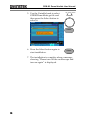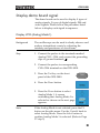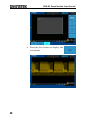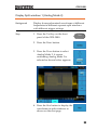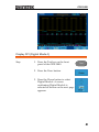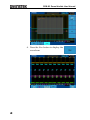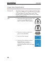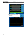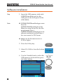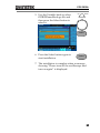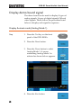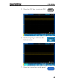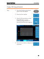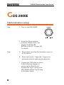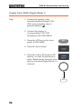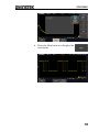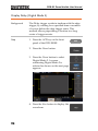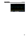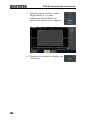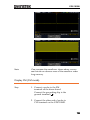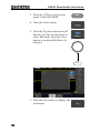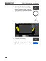
1
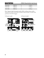
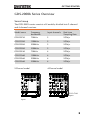
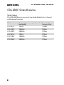
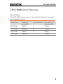
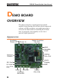
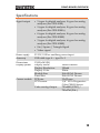
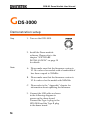
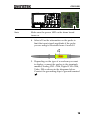
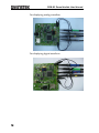
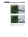
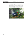
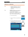
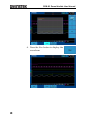
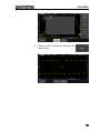
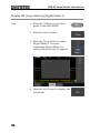
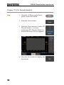
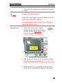
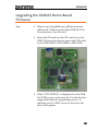
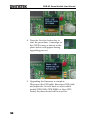
GDB-03 Demo Module USER MANUAL GW INSTEK PART NO. 82DB-03000EC1 ISO-9001 CERTIFIED MANUFACTURER This manual contains proprietary information, which is protected by copyright. All rights are reserved. No part of this manual may be photocopied, reproduced or translated to another language without prior written consent of Good Will company. The information in this manual was correct at the time of printing. However, Good Will continues to improve products and reserves the rights to change specification, equipment, and maintenance procedures at any time without notice. Good Will Instrument Co., Ltd. No. 7-1, Jhongsing Rd., Tucheng Dist., New Taipei City 236, Taiwan TABLE OF CONTENTS Table of Contents GETTING STARTED .......................................................... 3 GDS-3000 Series Overview ..................... 3 GDS-2000A Series Overview .................. 5 GDS-2000E Series Overview ................... 6 GDS-1000B Series Overview................... 7 Required tools ....................................... 8 Demonstration type ............................... 8 DEMO BOARD OVERVIEW ............................................. 12 Appearance .......................................... 12 Specifications ...................................... 13 GDS-3000 ...................................................................... 14 Demonstration setup ........................... 14 Software installation ............................ 19 Display demo board signal................... 21 GDS-2000A .................................................................... 53 Demonstration setup ........................... 53 Software installation ............................ 58 Display demo board signal................... 60 GDS-2000E .................................................................... 96 Demonstration setup ........................... 96 Software installation .......................... 101 Display demo board signal................. 103 GDS-1000B ................................................................... 135 Demonstration setup ......................... 135 Software installation .......................... 140 Display demo board signal................. 142 1 GDB-03 Demo Module User Manual APPENDIX .................................................................... 163 Upgrade Procedure ............................ 163 Upgrading the GDB-03 Demo Board Firmware ............................................ 167 2 GETTING STARTED GETTING STARTED Using the demo board specially designed for GDS-1000B, GDS-2000E, GDS-2000A, and GDS3000, you can verify and observe various advanced functionalities for demonstration or your own education. For viewing demo waveforms on the GDS-3000, please refer to page 14 through page 52. For viewing demo waveforms on the GDS-2000A, please refer to page 53 through page 95. For viewing demo waveforms on the GDS-2000E, please refer to page 96 through page 134. For viewing demo waveforms on the GDS-1000B, please refer to page 135 through page 162. GDS-3000 Series Overview Series lineup The GDS-3000 series consists of 6 models, divided into 2-channel and 4-channel versions. Model name Frequency bandwidth Input channels Real-time Sampling Rate GDS-3152 150MHz 2 2.5GSa/s GDS-3252 250MHz 2 2.5GSa/s GDS-3352 350MHz 2 5GSa/s GDS-3502 500MHz 2 4GSa/s GDS-3154 150MHz 4 5GSa/s 3 GDB-03 Demo Module User Manual GDS-3254 250MHz 4 5GSa/s GDS-3354 350MHz 4 5GSa/s GDS-3504 500MHz 4 4GSa/s The 2 channel and 4 channel models differ in the position of the horizontal controls, the math, reference and bus keys as well as the position of the EXT trigger. 2-Channel model 4-Channel model TRIGGER VARIABLE LEVEL HORIZONTAL VARIABLE POSITION Autoset Split Window Select LEVEL Split Window Select Display Cursor Test Acquire Menu Single 50 % Default Setup Help Save/Recall Utility VERTICAL POSITION Force - Trig Auto-Range Math, Reference Bus keys AC 50 W BW 75 W M REF AC 50 W BW 75 W R CH2 BUS VOLTS/DIV Test Acquire Display Help Save/Recall Utility TIME/DIV Horizontal controls 15pF 300Vpk MAX. 50 W & 75 W 5 Vrms MAX. CAT CH1 CH2 input input Single 50 % Default Setup Force - Trig POSITION Auto-Range EXT TRIG 1MW 15pF 300Vpk MAX. 50 W & 75 W 5 Vrms MAX. CAT EXT trigger POSITION MATH M AC 50 W AC 50 W BW 75 W BW 75 W Math, Reference Bus keys REF R CH1 CH2 BUS B1 VOLTS/DIV VOLTS/DIV B2 CH2 1MW Menu VERTICAL POSITION B2 CH1 4 Zoom B1 VOLTS/DIV Cursor POSITION POSITION MATH CH1 Measure HORIZONTAL POSITION Autoset Run/Stop Zoom TIME/DIV Measure TRIGGER Horizontal controls Run/Stop CH1 CH2 1MW AC 50 W AC 50 W BW 75 W BW 75 W CH3 CH4 VOLTS/DIV VOLTS/DIV CH3 CH4 15pF 300Vpk MAX. 50 W & 75 W 5 Vrms MAX. CAT CH1 CH2 CH3 CH4 input input input input GETTING STARTED GDS-2000A Series Overview Series lineup The GDS-2000A series consists of 8 models, divided into 2-channel and 4-channel versions. Model name Frequency bandwidth Input channels Real-time Sampling Rate GDS-2072A 70MHz 2 2GSa/s GDS-2102A 100MHz 2 2GSa/s GDS-2202A 200MHz 2 2GSa/s GDS-2302A 300MHz 2 2GSa/s GDS-2074A 70MHz 4 2GSa/s GDS-2104A 100MHz 4 2GSa/s GDS-2204A 200MHz 4 2GSa/s GDS-2304A 300MHz 4 2GSa/s 2-Channel model GDS-2202A Digital Storage Oscilloscope 200 MHz 2 GS/s 4-Channel model GDS-2204A VARIABLE Digital Storage Oscilloscope 200 MHz 2 GS/s VARIABLE Visual Persistence Oscilloscope Visual Persistence Oscilloscope Hardcopy Measure Cursor Test Acquire Autoset Display Help Save/Recall Utility Run/Stop HORIZONTAL Search Cursor Test Acquire Autoset Display Help Save/Recall Utility Run/Stop VERTICAL TRIGGER POSITION LEVEL POSITION POSITION MATH M M REF REF BUS GEN 2 Logic Analyzer 2V LEVEL CH3 CH4 Menu VOLTS/DIV VOLTS/DIV R CH2 Menu VOLTS/DIV 50 % B CH1 CH2 VOLTS/DIV VOLTS/DIV BUS B Menu Off 50 % Option Option GEN 1 TRIGGER POSITION POSITION MATH VOLTS/DIV Default Set/Clear R CH1 Zoom Default VERTICAL Menu Off Single TIME/DIV POSITION Select Search Zoom Set/Clear POSITION Measure HORIZONTAL Single TIME/DIV POSITION Select Hardcopy Force-Trig Force-Trig POWER CH2 CH1 1 M W 16pF 300Vpk MAX. CAT CH1~CH2 input GEN 1 GEN 2 LogicTRIG Analyzer EXT 1 M W 16pF 300Vpk MAX. CAT Demo CH1 CH2 CH3 1 M W 16pF 300Vpk MAX. CAT CH4 EXT TRIG 1 M W 16pF 300Vpk MAX. CAT CH1~CH4 input 5 GDB-03 Demo Module User Manual GDS-2000E Series Overview Series lineup The GDS-2000E series consists of 6 models, divided into 2-channel and 4-channel versions. Model name Frequency bandwidth Input channels Max. Real-time Sampling Rate GDS-2072E 70MHz 2 1GSa/s GDS-2102E 100MHz 2 1GSa/s GDS-2202E 200MHz 2 1GSa/s GDS-2074E 70MHz 4 1GSa/s GDS-2104E 100MHz 4 1GSa/s GDS-2204E 200MHz 4 1GSa/s 6 GETTING STARTED GDS-1000B Series Overview Series lineup The GDS-1000B series consists of 4 models, divided into 2-channel and 4-channel versions. Model name Frequency bandwidth Input channels Max. Real-time Sampling Rate GDS-1072B 70MHz 2 1GSa/s GDS-1102B 100MHz 2 1GSa/s GDS-1074B 70MHz 4 1GSa/s GDS-1104B 100MHz 4 1GSa/s 7 GDB-03 Demo Module User Manual Required tools GDS-3000 x 1 or GDS-2000A x 1 or GDS-2000E or GDS-1000B x 1 Demo board x 1 USB type A- type B cable x 1. Used for demo board’s power Standard oscilloscope probe x 4 DS2-08LA or DS2-16LA (For GDS-2000A) Demonstration type GDS-3000 VPO (page21) Split window 1 (page 23) Split window 2 (page 24) Auto Range Function (page 26) Autoset mode (page 27) XY mode (page 30) Gating Measurement (page 32) Pulse Runt (page 33) Rise Fall (page 35) Pulse Width (page 36) UART (page 38) I2C (page 40) SPI (page 41) Delay(page 43) FM (page 45) Video (page 47) Generator (page 49) 8 GETTING STARTED GDS-2000A Autoset mode (page 60) Gating Measurement (page 64) Pulse Runt (page 65) Rise Fall (page 67) Search (page 68) Segments (page 70) Parallel (page 71) Pulse Width (page 73) Delay (page 75) LM(Long Memory)(page 77) Logic (page 79) UART (page 80) I2C (page 82) SPI (page 83) CAN(page 85) LIN(page 86) FM (page 87) Video (page 90) Generator (page 92) XY mode (page 62) 9 GDB-03 Demo Module User Manual GDS-2000E Autoset mode (page 103) XY mode (page 105) Gating Measurement (page 107) Pulse Runt (page 108) Rise Fall (page 110) Search (page 111) Segments (page 113) Update (page 114) Pulse Width (page 116) Delay (page 118) LM(Long Memory)(page 120) FM (page 121) Generator(page 123) Video (page 127) UART (CH Decode Mode) (page 128) I2C (CH Decode Mode) (page 130) SPI (CH Decode Mode) (page 131) CAN (CH Decode Mode) (page 132) LIN (CH Decode Mode) (page 133) 10 GETTING STARTED GDS-1000B Autoset mode (page 142) XY mode (page 144) Gating Measurement (page 145) Pulse Runt (page 147) Rise Fall (page 148) Update (page 149) Pulse Width (page 150) Delay (page 152) LM(Long Memory)(page 153) FM (page 155) Generator(page 157) Video (page 161) 11 GDB-03 Demo Module User Manual DEMO BOARD OVERVIEW The demo board is a signal generator board capable of producing waveforms which represent various real life scenarios you might encounter. You can use the board as a training kit to learn how to properly view signals, or use it as a generic signal generator. Appearance Auxiliary Power in Power in Select Function key key GND Variable Knob Camera Module Analog Ch1~Ch4 SD Card OLED Display LA input GND (For 2000A only) Video FM GND Function Generator 12 Digital Ch1~Ch4 DEMO BOARD OVERVIEW Specifications Signal output 5 types for digital analyzer, 9 types for analog analyzer (For GDS-3000) 9 types for digital analyzer, 8 types for analog analyzer (For GDS-2000A) 8 types for digital analyzer, 8 types for analog analyzer (For GDS-2000E) 3 types for digital analyzer, 6 types for analog analyzer (For GDS-1000B) Sin / Square / Triangle Signal Video signal Power supply 5V DC, USB or auxiliary power input Accessory USB cable type A – type B x 1 Dimensions Display system 13(W)x14.5(H) Display Mode Display Resolution Display Color Module Size Panel Size PCB size CCD sensor Camera module Video analog Output Passive Matrix 128x64 White 26.4x28.5x1.26 mm 26.4x19.7x1.26 mm 32x32 mm 1/4’’ VGA Progressive Color CMOS Sensor 720x480I(NTSC) / 720x576I(PAL) 13 GDB-03 Demo Module User Manual GDS-3000 Demonstration setup Step 1. Turn on the GDS-3000. 2. Install the Demo module software. Please refer to the chapter “SOFTWARE INSTALLATION” on page 19 for details. Note A. Please make sure that the firmware version is V1.14 or above for models with a bandwidth of less than or equal to 350MHz. B. Please make sure that the firmware version is V1.0 or above for the model with 500MHz. C. Please refer to the “Appendix” chapter for information about updating the firmware. 3. Connect the USB cable as shown in the following diagram to power up the demo board. Connect the Type A plug to the GDS-3000 and the Type B plug to the demo board. 14 GDS-3000 GDS-3354 VARIABLE Digital Storage Oscilloscope 350 MHz 5 GS/s Visual Persistence Oscilloscope HORIZONTAL TRIGGER POSITION LEVEL Autoset Print Run/Stop Save Zoom Split Window Select Menu Single TIME/DIV Measure Cursor Test Acquire 50 % Default Setup Display Help Save/Recall Utility Force - Trig Auto-Range VERTICAL POSITION POSITION POSITION POSITION MATH M AC 50 W AC 50 W BW 75 W BW 75 W REF AC 50 W BW 75 W AC 50 W BW 75 W R CH1 BUS CH2 Menu Off CH3 CH4 VOLTS/DIV VOLTS/DIV CH3 CH4 B1 VOLTS/DIV VOLTS/DIV B2 POWER 2V EXT TRIG CH1 1MW 15pF 300Vpk MAX. 50 W & 75 W 5 Vrms MAX. CAT Note CH2 1MW 15pF 300Vpk MAX. 50 W & 75 W 5 Vrms MAX. CAT Make sure the power LED on the demo board turns on. 4. Select x10 as the attenuation on the probe to limit the input signal amplitude if the probe you are using is selectable from x1 and x10. 5. Depending on the type of waveform you want to display, connect the probes to the terminals marked, Analog CH1~CH4, Digital CH1~CH4, Video, FM as shown in the diagrams below. Connect the grounding clips to ground terminal ( ). 15 GDB-03 Demo Module User Manual For displaying analog waveform For displaying digital waveform 16 GDS-3000 For displaying FM waveform For displaying video waveform 6. Connect the other end of the probe(s) to the corresponding CH1 to CH4 terminals on the GDS-3000. 17 GDB-03 Demo Module User Manual 7. Adjust the Variable knob on the demo board to select which oscilloscope to demonstrate when the USB cable is connected to the demo board and the oscilloscope. The GDS-3000 is selected when it is highlighted on the OLED display. 18 GDS-3000 Software installation Step 1. Insert the USB memory stick with GDB03DemoMode.gz into the USB port on the front panel of the GDS-3000. Note GDB03DemoMode.gz comes from the GDB03DemoMode.zip file. When you unzip the zip file, two files are generated. One is GDB03DemoMode.gz for the software installation and the other is this user manual in PDF format. 2. Press the Utility key. Utility 3. Select File Utilities from the bottom menu. 4. Use the Variable knob to select the USB memory stick and then press the Select button. Up Down VARIABLE Select 19 GDB-03 Demo Module User Manual 5. Use the Variable knob to select GDB03DemoMode.gz file and then press the Select button to select it. Up Down VARIABLE Select 6. Press the Select button again to start installation. Select 7. The installation is complete when a message showing “Please turn off the oscilloscope and turn on again” is displayed. 20 GDS-3000 Display demo board signal The demo board can be used to display 9 types of analog signals, 5 types of digital signals, FM and video signals. Please follow the procedure listed below to display each signal in sequence. Display VPO (Analog Mode 1) Background The oscilloscope can be used to clearly observe and analyze intermittent events by adjusting the intensity and persistence of waveforms. Step 1. Connect the probes to the terminals marked Analog CH1~ CH4, and connect the grounding clips to ground terminal ( ). 2. Connect the probes to corresponding CH1~CH4 terminals on the GDS-3000. 3. Press the Test key on the front panel of the GDS-3000. Test 4. Press the Demo button. 5. Press the Down button to select Analog Mode 1. A screen confirming that Analog Mode 1 is selected as shown on the next page appears. Note If the Analog Mode is not selected, press the F1 button on the side menu. Use the Variable knob to select Analog Mode. Press the Select button to confirm Analog Mode 1 is selected. (Refer to Page 37 step 5) 21 GDB-03 Demo Module User Manual 6. Press the Run button to display the waveform. 22 GDS-3000 Display Split windows 1 (Analog Mode 2) Background Display 4 unsynchronized waveforms at different frequencies in different separate split windows with different trigger settings Step 1. Press the Test key on the front panel of the GDS-3000. Test 2. Press the Demo button. 3. Press the Down button to select Analog Mode 2. A screen confirming Analog Mode 2 is selected as shown below appears. 4. Press the Run button to display the waveforms in split windows as shown on the next page. 23 GDB-03 Demo Module User Manual Display Split windows 2 (Analog Mode 3) Background Display a signal (a more complex signal) that can have different settings and be displayed in four split windows. Step 1. Press the Test key on the front panel of the GDS-3000. 2. Press the Demo button. 3. Press the Down button to select Analog Mode 3. A screen confirming Analog Mode 3 is selected as shown on the next page appears. 24 Test GDS-3000 4. Press the Run button to display a waveform in split window as shown below. 25 GDB-03 Demo Module User Manual Display Auto-Range Function (Analog Mode 4) Background Demonstrate that the oscilloscope can automatically be adjusted to the best range setting according to changes in the input signal. Step 1. Press the Test key on the front panel of the GDS-3000. Test 2. Press the Demo button. 3. Press the Down button to select Analog Mode 4. A screen confirming Analog Mode 4 is selected as shown below appears. 4. Press the Run button and AutoRange key to display the waveform. Auto-Range 26 GDS-3000 Display Autoset mode (Analog Mode 5) Step 1. Press the Test key on the front panel of the GDS-3000. Test 2. Press the Demo button. 3. Press the Down button to select Analog Mode 5. A screen confirming Analog Mode 5 is selected as shown on the next page appears. 27 GDB-03 Demo Module User Manual 4. Press the Run button. 5. Press the CH1 key to activate CH1. 6. Set the Coupling to AC from the bottom menu. 28 CH1 GDS-3000 7. Press the Autoset key on the panel. Autoset 8. A waveform as shown below appears. 29 GDB-03 Demo Module User Manual Display XY mode (Analog Mode 6) Background Display 2 sets of X-Y waveform at the same time. Step 1. Press the Test key on the front panel of the GDS-3000. 2. Press the Demo button. 3. Press the Down button to select Analog Mode 6. A screen confirming Analog Mode 6 is selected as shown below appears. 4. Press the Run button to display the waveform. 30 Test GDS-3000 31 GDB-03 Demo Module User Manual Display Gating Measurement (Analog Mode 7) Step 1. Press the Test key on the front panel of the GDS-3000. 2. Press the Demo button. 3. Press the Down button to select Analog Mode 7. A screen confirming Analog Mode 7 is selected as shown below appears. 4. Press the Run button to display the waveform. 32 Test GDS-3000 Note You can set the position of the cursors to set the range of the Gating Measurement. Display Pulse Runt (Analog Mode 8) Step 1. Press the Test key on the front panel of the GDS-3000. Test 2. Press the Demo button. 3. Press the Down button to select Analog Mode 8. A screen confirming Analog Mode 8 is selected as shown on the next page appears. 33 GDB-03 Demo Module User Manual 4. Press the Run button to display the waveform. 34 GDS-3000 Display Rise Fall (Analog Mode 9) Step 1. Press the Test key on the front panel of the GDS-3000. Test 2. Press the Demo button. 3. Press the Down button to select Analog Mode 9. A screen confirming Analog Mode 9 is selected as shown below appears. 4. Press the Run button to display the waveform. 35 GDB-03 Demo Module User Manual Display Pulse Width (Digital Mode 1) Step 1. Connect the probes to the terminals marked Digital CH1~ CH4, and grounding clips to ground terminal ( ). 2. Connect the probes to corresponding CH1~CH4 terminals on the GDS-3000. 3. Press the Test key on the front panel of the GDS-3000. 4. Press the Demo button. 36 Test GDS-3000 5. Press the Analog Mode button (F1 button). Use the Variable knob to select Digital mode. Press the Select button to confirm Digital Mode 1 is selected. Up Down VARIABLE Select 6. Press the Run button to display the waveform. 37 GDB-03 Demo Module User Manual Display UART (Digital Mode 2) Step 1. Press the Test key on the front panel of the GDS-3000. 2. Press the Demo button. 3. Press the Down button to select Digital Mode 2. A screen confirming Digital Mode 2 is selected as shown on the next page appears. 38 Test GDS-3000 4. Press the Run button to display the waveform. 39 GDB-03 Demo Module User Manual Display I2C (Digital Mode 3) Step 1. Press the Test key on the front panel of the GDS-3000. 2. Press the Demo button. 3. Press the Down button to select Digital Mode 3. A screen confirming Digital Mode 3 is selected as shown below appears. 4. Press the Run button to display the waveform. 40 Test GDS-3000 Display SPI (Digital Mode 4) Step 1. Press the Test key on the front panel of the GDS-3000. Test 2. Press the Demo button. 3. Press the Down button to select Digital Mode 4. A screen confirming Digital Mode 4 is selected as shown on the next page appears. 41 GDB-03 Demo Module User Manual 4. Press the Run button to display the waveform. 42 GDS-3000 Display Delay (Digital Mode 5) Background The Delay trigger works in tandem with the edge trigger, by waiting for a specified time or number of events before the edge trigger starts. This method allows pinpointing a location in a long series of trigger events. Step 1. Disconnect the probe from the CH2 terminal on the GDS-3000 and move to the EXT TRIG terminal 2 2. Press the Test key on the front panel of the GDS-3000. 3. Press the Demo button. 4. Press the Down button to select Digital Mode 5. A screen confirming Digital Mode 5 is selected as shown on the next page appears. 43 Test GDB-03 Demo Module User Manual 5. Press the Run button to display the waveform. 44 GDS-3000 Display FM (FM mode) Step 1. Connect a probe to the FM terminal on the demo board. Connect the grounding clip to the ground terminal ( ). 2. Connect the other end of probe to CH1 terminal on the GDS-3000. 3. Press the Test key on the front panel of the GDS-3000. Test 4. Press the Demo button. 5. Press the Digital mode button (F1 button). Use the Variable knob to select FM mode. Press the Select button to confirm FM Mode 1 is selected. Up Down VARIABLE Select 45 GDB-03 Demo Module User Manual 6. Press the Run button to display the waveform. 46 GDS-3000 Display Video (Video mode) Step 1. Connect a probe to the Video terminal on the demo board. Connect the grounding clip to the ground terminal ( ). 2. Connect the other end of probe to the CH1 terminal on the GDS-3000. 3. Press the Test key on the front panel of the GDS-3000. Test 4. Press the Demo button. 5. Press FM button (F1 button). Use the Variable knob to select Video mode. Press the Select button to confirm Video Mode 1 is selected. Up Down VARIABLE Select 47 GDB-03 Demo Module User Manual 6. Press the Run button to display the waveform. 48 GDS-3000 Display Sine, Square and Triangle waveform (Generator mode) 1. Connect the probe to the terminal marked on the demo board. Connect the grounding clip to the ground terminal ( ). 2. Connect the other end of probe to the CH1 terminal on the GDS-3000. 3. Press the Test key on the front panel of the GDS-3000. Test 4. Press the Demo button. 5. Press the Video Mode button (F1 button). Use the Variable knob to select Generator mode. Press the Select button to confirm Generator Mode 1 is selected. Up Down VARIABLE Select 49 GDB-03 Demo Module User Manual 6. Press the Run button. 7. Press the AutoSet button to display the Sine waveform. 8. Press the Select button on the demo board. 50 Autoset GDS-3000 9. Adjust the Variable knob on the demo board to select the Wave Type. Wave Type is selected when it is highlighted on the OLED display. Generator Wave Type Sin 10. Push the Select button to change the highlight to the bottom line on the OLED display. Generator Wave Type Sin 11. Adjust the Variable knob on the demo board to select Square. Square is selected when it is highlighted on the OLED display. 12. Press the AutoSet button to display the Square waveform. Generator Wave Type Square Autoset 51 GDB-03 Demo Module User Manual 13. Adjust the Variable knob on the demo board to select Triangle. Triangle is selected when it is highlighted on the OLED display. 14. Press the AutoSet button to display the Triangle waveform. 52 Generator Wave Type Triangle Autoset GDS-2000A GDS-2000A Demonstration setup Step 1. Turn on the GDS-2000A. POWER 2. Install the Demo module software. Please refer to the chapter “SOFTWARE INSTALLATION” on page 58 for details. Note A. Please make sure that the firmware version is V1.09 or above. B. Please refer to the “Appendix” chapter for information about updating the firmware. 3. Connect the USB cable as shown in the following diagram to power up the demo board. Connect the Type A plug to the GDS-2000A and the Type B plug to the demo board. 53 GDB-03 Demo Module User Manual GDS-2204A Digital Storage Oscilloscope 200 MHz 2 GS/s VARIABLE Visual Persistence Oscilloscope Hardcopy Measure Cursor Display Help Test Save/Recall Acquire Autoset Utility Run/Stop HORIZONTAL Search Single TIME/DIV POSITION Select Zoom Default Set/Clear VERTICAL POSITION POSITION CH1 CH2 VOLTS/DIV VOLTS/DIV TRIGGER POSITION POSITION LEVEL MATH M REF R BUS CH3 CH4 VOLTS/DIV VOLTS/DIV Menu B Menu Off 50 % Option POWER GEN 1 GEN 2 Logic Analyzer Demo Force-Trig CH1 CH2 CH3 1 M W 16pF 300Vpk MAX. CAT Note CH4 EXT TRIG 1 M W 16pF 300Vpk MAX. CAT Make sure the power LED on the demo board turns on. 4. Select x10 as the attenuation on the probe to limit the input signal amplitude if the probe you are using is selectable from x1 and x10. 5. Depending on the type of waveform you want to display, connect the probes to the terminals marked, Analog CH1~CH4, Digital CH1~CH4, Video, FM as shown in the diagrams below. Connect the grounding clips to ground terminal ( ). 54 GDS-2000A For displaying analog waveform For displaying digital waveform 55 GDB-03 Demo Module User Manual For displaying FM waveform For displaying video waveform 6. Connect the other end of the probe(s) to the corresponding CH1 to CH4 terminals on the GDS-2000A. 56 GDS-2000A 7. Connect the GDS-2000A and the demo board with the Logic Analyzer Probe as shown in the photo below for displaying the LA source. 8. Adjust the Variable knob on the demo board to select which oscilloscope to demonstrate when the USB cable is connected to the demo board and the oscilloscope. The GDS-2000A is selected when it is highlighted on the OLED display. 57 GDB-03 Demo Module User Manual Software installation Step 1. Insert the USB memory stick with GDB03DemoMode.gz into the USB port on the front panel of the GDS-2000A. Note GDS2kAGDB03DemoMode.gz comes from the GDS2kAGDB03DemoMode.zip file. When you unzip the zip file, two files are generated. One is GDS2kAGDB03DemoMode.gz for the software installation and the other is this user manual in PDF format. Make sure the firmware version is V1.09 or higher. 2. Press the Utility key. Utility 3. Select File Utilities from the bottom menu. 4. Use the Variable knob to select the USB memory stick and then press the Select button. Up Select 58 Down VARIABLE GDS-2000A 5. Use the Variable knob to select GDB03DemoMode.gz file and then press the Select button to select it. Up Down VARIABLE Select 6. Press the Select button again to start installation. Select 7. The installation is complete when a message showing “Please turn off the oscilloscope and turn on again” is displayed. 59 GDB-03 Demo Module User Manual Display demo board signal The demo board can be used to display 8 types of analog signals, 9 types of digital signals, FM and video signals. Please follow the procedure listed below to display each signal in sequence. Display Autoset mode (Analog Mode 1) Step 1. Press the Test key on the front panel of the GDS-2000A. 2. Press the Demo button. 3. Press the Down button to select Analog Mode 1. A screen confirming Analog Mode 1 is selected as shown below appears. 4. Press the Run button. 60 Test GDS-2000A 5. Press the CH1 key to activate CH1. CH1 6. Set the Coupling to AC from the bottom menu. 7. Press the Autoset key on the panel. Autoset 61 GDB-03 Demo Module User Manual 8. A waveform as shown below appears. Display XY mode(Analog Mode 2) Background Display 2 sets of X-Y waveform at the same time. Step 1. Press the Test key on the front panel of GDS-2000A. 2. Press the Demo button. 3. Press the Down button to select Analog Mode 2. A screen confirming Analog Mode 2 is selected as shown on the next page appears. 62 Test GDS-2000A 4. Press the Run button to display the waveform. 63 GDB-03 Demo Module User Manual Display Gating Measurement (Analog Mode 3) Step 1. Press the Test key on the front panel of the GDS-2000A. 2. Press the Demo button. 3. Press the Down button to select Analog Mode 3. A screen confirming Analog Mode 3 is selected as shown below appears. 4. Press the Run button to display the waveform. 64 Test GDS-2000A Note You can set the position of the cursors to set the range of the Gating Measurement. Display Pulse Runt (Analog Mode 4) Step 1. Press the Test key on the front panel of the GDS-2000A. Test 2. Press the Demo button. 3. Press the Down button to select Analog Mode 4. A screen confirming Analog Mode 4 is selected as shown on the next page appears. 65 GDB-03 Demo Module User Manual 4. Press the Run button to display the waveform. 66 GDS-2000A Display Rise Fall (Analog Mode 5) Step 1. Press the Test key on the front panel of the GDS-2000A. Test 2. Press the Demo button. 3. Press the Down button to select Analog Mode 5. A screen confirming Analog Mode 5 is selected as shown below appears. 4. Press the Run button to display the waveform. 67 GDB-03 Demo Module User Manual Display Search (Analog Mode 6) Step 1. Press the Test key on the front panel of the GDS-2000A. 2. Press the Demo button. 3. Press the Down button to select Analog Mode 6. A screen confirming Analog Mode 6 is selected as shown on the next page appears. 68 Test GDS-2000A 4. Press the Run button to display the waveform. 69 GDB-03 Demo Module User Manual Display Segments (Analog Mode 7) Step 1. Press the Test key on the front panel of the GDS-2000A. 2. Press the Demo button. 3. Press the Down button to select Analog Mode 7. A screen confirming Analog Mode 7 is selected as shown below appears. 4. Press the Run button to display the waveform. 5. The function key on the demo board should be press down before the segments waveform can be outputted. 70 Test GDS-2000A Display Parallel (Analog Mode 8) Step 1. Press the Test key on the front panel of the GDS-2000A. Test 2. Press the Demo button. 3. Press the Down button to select Analog Mode 8. A screen confirming Analog Mode 8 is selected as shown on the next page appears. 71 GDB-03 Demo Module User Manual 4. Press the Run button to display the waveform. 72 GDS-2000A Display Pulse Width (Digital Mode 1) Step 1. Connect the probes to the terminals marked Digital CH1~ CH4, and grounding clips to ground terminal ( ). 2. Connect the probes to corresponding CH1~CH4 terminals on the GDS-2000A. 3. Press the Test key on the front panel of GDS-2000A. Test 4. Press the Demo button. 5. Press the Analog Mode button (F1 button). Use the Variable knob to select Digital mode. Press the Select button to confirm Digital Mode 1 is selected. Up Down VARIABLE Select 73 GDB-03 Demo Module User Manual 6. Press the Run button to display the waveform. 74 GDS-2000A Display Delay (Digital Mode 2) Background The Delay trigger works in tandem with the edge trigger, by waiting for a specified time or number of events before the edge trigger starts. This method allows pinpointing a location in a long series of trigger events. Step 1. Disconnect the probe from the CH2 terminal on the GDS-2000A and move to the EXT TRIG terminal CH2 EXT TRIG 2. Press the Test key on the front panel of the GDS-2000A. Test 3. Press the Demo button. 4. Press the Down button to select Digital Mode 2. A screen confirming Digital Mode 2 is selected as shown on the next page appears. 75 GDB-03 Demo Module User Manual 5. Press the Run button to display the waveform. 76 GDS-2000A Display LM (Logic Memory)(Digital Mode 3) Step 1. Press the Test key on the front panel of the GDS-2000A. Test 2. Press the Demo button. 3. Press the Down button to select Digital Mode 3. A screen confirming Digital Mode 3 is selected as shown below appears. 4. Press the Run button to display the waveform. 77 GDB-03 Demo Module User Manual Note 78 If we compare the waveforms shown above, we can see that we can observe more of the waveform under long memory. GDS-2000A Display Logic (Digital Mode 4) Step 1. Press the Test key on the front panel of the GDS-2000A. Test 2. Press the Demo button. 3. Press the Down button to select Digital Mode 4. A screen confirming Digital Mode 4 is selected as shown below appears. 4. Press the Run button to display the waveform. 79 GDB-03 Demo Module User Manual Display UART (Digital Mode 5) Step 1. Press the Test key on the front panel of the GDS-2000A. 2. Press the Demo button. 3. Press the Down button to select Digital Mode 5. A screen confirming Digital Mode 5 is selected as shown below appears. 80 Test GDS-2000A 4. Press the Run button to display the waveform. 81 GDB-03 Demo Module User Manual Display I2C (Digital Mode 6) Step 1. Press the Test key on the front panel of the GDS-2000A. 2. Press the Demo button. 3. Press the Down button to select Digital Mode 6. A screen confirming Digital Mode 6 is selected as shown below appears. 4. Press the Run button to display the waveform. 82 Test GDS-2000A Display SPI (Digital Mode 7) Step 1. Press the Test key on the front panel of the GDS-2000A. Test 2. Press the Demo button. 3. Press the Down button to select Digital Mode 7. A screen confirming Digital Mode 7 is selected as shown on the next page appears. 83 GDB-03 Demo Module User Manual 4. Press the Run button to display the waveform. 84 GDS-2000A Display CAN (Digital Mode 8) Step 1. Press the Test key on the front panel of the GDS-2000A. Test 2. Press the Demo button. 3. Press the Down button to select Digital Mode 8. A screen confirming Digital Mode 8 is selected as shown below appears. 4. Press the Run button to display the waveform. 85 GDB-03 Demo Module User Manual Display LIN (Digital Mode 9) Step 1. Press the Test key on the front panel of the GDS-2000A. 2. Press the Demo button. 3. Press the Down button to select Digital Mode 9. A screen confirming Digital Mode 9 is selected as shown on the next page appears. 86 Test GDS-2000A 4. Press the Run button to display the waveform. Display FM (FM mode) Step 1. Connect a probe to the FM terminal on the demo board. Connect the grounding clip to the ground terminal ( ). 87 GDB-03 Demo Module User Manual 2. Connect the other end of probe to CH1 terminal on the GDS-2000A. 3. Press the Test key on the front panel of the GDS-2000A. Test 4. Press the Demo button. 5. Press the Digital mode button (F1 button). Use the Variable knob to select FM mode. Press the Select button to confirm FM Mode 1 is selected. Up Down VARIABLE Select 6. Press the Run button to display the waveform. 88 GDS-2000A 89 GDB-03 Demo Module User Manual Display Video (Video mode) Step 1. Connect a probe to the Video terminal on the demo board. Connect the grounding clip to the ground terminal ( ). 2. Connect the other end of probe to the CH1 terminal on the GDS-2000A. 3. Press the Test key on the front panel of the GDS-2000A. Test 4. Press the Demo button. 5. Press FM button (F1 button). Use the Variable knob to select Video mode. Press the Select button to confirm Video Mode 1 is selected. Up Down VARIABLE Select 90 GDS-2000A 6. Press the Run button to display the waveform. 91 GDB-03 Demo Module User Manual Display Sine, Square and Triangle waveform (Generator mode) 1. Connect the probe to the terminal marked on the demo board. Connect the grounding clip to the ground terminal ( ). 2. Connect the other end of probe to the CH1 terminal on the GDS-2000A. 3. Press the Test key on the front panel of the GDS-2000A. Test 4. Press the Demo button. 5. Press the Video Mode button (F1 button). Use the Variable knob to select Generator mode. Press the Select button to confirm Generator Mode 1 is selected. Up Down VARIABLE Select 92 GDS-2000A 6. Press the Run button. 7. Press the AutoSet button to display the Sine waveform. Autoset 8. Press the Select button on the demo board. 93 GDB-03 Demo Module User Manual 9. Adjust the Variable knob on the demo board to select the Wave Type. Wave Type is selected when it is highlighted on the OLED display. Generator Wave Type Sin 10. Push the Select button to change the highlight to the bottom line on the OLED display. Generator Wave Type Sin 11. Adjust the Variable knob on the demo board to select Square. Square is selected when it is highlighted on the OLED display. 12. Press the AutoSet button to display the Square waveform. 94 Generator Wave Type Square Autoset GDS-2000A 13. Adjust the Variable knob on the demo board to select Triangle. Triangle is selected when it is highlighted on the OLED display. 14. Press the AutoSet button to display the Triangle waveform. Generator Wave Type Triangle Autoset 95 GDB-03 Demo Module User Manual GDS-2000E Demonstration setup Step 1. Turn on the GDS-2000E. POWER 2. Install the Demo module software. Please refer to the chapter “SOFTWARE INSTALLATION” on page 101 for details. Note A. Please make sure that the firmware version is V1.0 or above. B. Please refer to the “Appendix” chapter for information about updating the firmware. 3. Connect the USB cable as shown in the following diagram to power up the demo board. Connect the Type A plug to the GDS-2000E and the Type B plug to the demo board. 96 GDS-2000E GDS-2202E VARI ABLE SCALE CH1 SCALE CH2 EXT T RI G POWER Note Make sure the power LED on the demo board turns on. 4. Select x10 as the attenuation on the probe to limit the input signal amplitude if the probe you are using is selectable from x1 and x10. 5. Depending on the type of waveform you want to display, connect the probes to the terminals marked, Analog CH1~CH4, Digital CH1~CH4, Video, FM as shown in the diagrams below. Connect the grounding clips to ground terminal ( ). 97 GDB-03 Demo Module User Manual For displaying analog waveform For displaying digital waveform 98 GDS-2000E For displaying FM waveform For displaying video waveform 6. Connect the other end of the probe(s) to the corresponding CH1 to CH4 terminals on the GDS-2000E. 99 GDB-03 Demo Module User Manual 7. Adjust the Variable knob on the demo board to select which oscilloscope to demonstrate when the USB cable is connected to the demo board and the oscilloscope. The New GDS-Series is selected when it is highlighted on the OLED display. 100 GDS-2000E Software installation Step 1. Insert the USB memory stick with GDB03.fun into the USB port on the front panel of the GDS-2000E. Note GDB03.fun comes from the GDB03.zip file. When you unzip the zip file, two files are generated. One is GDB03.fun for the software installation and the other is this user manual in PDF format. Make sure the firmware version is V1.00 or higher. 2. Press the Utility key. Utility 3. Select File Utilities from the bottom menu. 4. Use the Variable knob to select the USB memory stick and then press the Select button. VARIABLE Select 101 GDB-03 Demo Module User Manual 5. Use the Variable knob to select GDB03.fun file and then press the Select button to select it. VARIABLE Select 6. Press the Select button again to start installation. Select 7. The installation is complete when a message showing “Please turn off the oscilloscope and turn on again” is displayed. 102 GDS-2000E Display demo board signal The demo board can be used to display 8 types of analog signals, 8 types of digital signals, 5 types of CH decode signals, FM and video signals. Please follow the procedure listed below to display each signal in sequence. Display Autoset mode (Analog Mode 1) Step 1. Press the APP key on the front panel of the GDS-2000E. APP 2. Press the Demo button. 3. Press the Down button to select Analog Mode 1. A screen confirming Analog Mode 1 is selected as shown below appears. 4. Press the Run button. 103 GDB-03 Demo Module User Manual 5. Press the CH1 key to activate CH1. CH1 6. Set the Coupling to AC from the bottom menu. 7. Press the Autoset key on the panel. Autoset 8. A waveform shown as the next page appears. 104 GDS-2000E Display XY mode(Analog Mode 2) Background Display 2 sets of X-Y waveform at the same time. Step 1. Press the APP key on the front panel of GDS-2000E. APP 2. Press the Demo button. 3. Press the Down button to select Analog Mode 2. A screen confirming Analog Mode 2 is selected as shown on the next page appears. 105 GDB-03 Demo Module User Manual 4. Press the Run button to display the waveform. 106 GDS-2000E Display Gating Measurement (Analog Mode 3) Step 1. Press the APP key on the front panel of the GDS-2000E. APP 2. Press the Demo button. 3. Press the Down button to select Analog Mode 3. A screen confirming Analog Mode 3 is selected as shown below appears. 4. Press the Run button to display the waveform. 107 GDB-03 Demo Module User Manual Note You can set the position of the cursors to set the range of the Gating Measurement. Display Pulse Runt (Analog Mode 4) Step 1. Press the APP key on the front panel of the GDS-2000E. 2. Press the Demo button. 3. Press the Down button to select Analog Mode 4. A screen confirming Analog Mode 4 is selected as shown on the next page appears. 108 APP GDS-2000E 4. Press the Run button to display the waveform. 109 GDB-03 Demo Module User Manual Display Rise Fall (Analog Mode 5) Step 1. Press the APP key on the front panel of the GDS-2000E. 2. Press the Demo button. 3. Press the Down button to select Analog Mode 5. A screen confirming Analog Mode 5 is selected as shown below appears. 4. Press the Run button to display the waveform. 110 APP GDS-2000E Display Search (Analog Mode 6) Step 1. Press the APP key on the front panel of the GDS-2000E. APP 2. Press the Demo button. 3. Press the Down button to select Analog Mode 6. A screen confirming Analog Mode 6 is selected as shown below appears. 111 GDB-03 Demo Module User Manual 4. Press the Run button to display the waveform. 112 GDS-2000E Display Segments (Analog Mode 7) Step 1. Press the APP key on the front panel of the GDS-2000E. APP 2. Press the Demo button. 3. Press the Down button to select Analog Mode 7. A screen confirming Analog Mode 7 is selected as shown below appears. 4. Press the Run button to display the waveform. 5. The function key on the demo board should be press down before the segments waveform can be outputted. 113 GDB-03 Demo Module User Manual Display Update (Analog Mode 9) Step 1. Press the APP key on the front panel of the GDS-2000E. 2. Press the Demo button. 3. Press the Down button to select Analog Mode 9. A screen confirming Analog Mode 9 is selected as shown on the next page appears. 114 APP GDS-2000E 4. Press the Run button to display the waveform. 115 GDB-03 Demo Module User Manual Display Pulse Width (Digital Mode 1) Step 1. Connect the probes to the terminals marked Digital CH1~ CH4, and grounding clips to ground terminal ( ). 2. Connect the probes to corresponding CH1~CH4 terminals on the GDS-2000A. 3. Press the APP key on the front panel of GDS-2000E. APP 4. Press the Demo button. 5. Press the Analog Mode button (F1 button). Use the Variable knob to select Digital mode. Press the Select button to confirm Digital Mode 1 is selected. VARIABLE Select 116 GDS-2000E 6. Press the Run button to display the waveform. 117 GDB-03 Demo Module User Manual Display Delay (Digital Mode 2) Background The Delay trigger works in tandem with the edge trigger, by waiting for a specified time or number of events before the edge trigger starts. This method allows pinpointing a location in a long series of trigger events. Step 1. Press the APP key on the front panel of the GDS-2000E. 2. Press the Demo button. 3. Press the Down button to select Digital Mode 2. A screen confirming Digital Mode 2 is selected as shown on the next page appears. 4. Press the Run button to display the waveform. 118 APP GDS-2000E 119 GDB-03 Demo Module User Manual Display LM (Logic Memory)(Digital Mode 3) Step 1. Press the APP key on the front panel of the GDS-2000E. 2. Press the Demo button. 3. Press the Down button to select Digital Mode 3. A screen confirming Digital Mode 3 is selected as shown below appears. 4. Press the Run button to display the waveform. 120 APP GDS-2000E Note If we compare the waveforms shown above, we can see that we can observe more of the waveform under long memory. Display FM (FM mode) Step 1. Connect a probe to the FM terminal on the demo board. Connect the grounding clip to the ground terminal ( ). 2. Connect the other end of probe to CH1 terminal on the GDS-2000E. 121 GDB-03 Demo Module User Manual 3. Press the APP key on the front panel of the GDS-2000E. APP 4. Press the Demo button. 5. Press the Digital mode button (F1 button). Use the Variable knob to select FM mode. Press the Select button to confirm FM Mode 1 is selected. VARIABLE Select 6. Press the Run button to display the waveform. 122 GDS-2000E Display Sine, Square and Triangle waveform (Generator mode) 1. Connect the probe to the terminal marked on the demo board. Connect the grounding clip to the ground terminal ( ). 2. Connect the other end of probe to the CH1 terminal on the GDS2000E. 3. Press the APP key on the front panel of the GDS-2000E. APP 4. Press the Demo button. 123 GDB-03 Demo Module User Manual 5. Press the FM Mode button (F1 button). Use the Variable knob to select Generator mode. Press the Select button to confirm Generator Mode 1 is selected. VARIABLE Select 6. Press the Run button. 7. Press the AutoSet button to display the Sine waveform. 124 Autoset GDS-2000E 8. Press the Select button on the demo board. 9. Adjust the Variable knob on the demo board to select the Wave Type. Wave Type is selected when it is highlighted on the OLED display. Generator Wave Type Sin 10. Push the Select button to change the highlight to the bottom line on the OLED display. Generator Wave Type Sin 11. Adjust the Variable knob on the demo board to select Square. Square is selected when it is highlighted on the OLED display. Generator Wave Type Square 125 GDB-03 Demo Module User Manual 12. Press the AutoSet button to display the Square waveform. 13. Adjust the Variable knob on the demo board to select Triangle. Triangle is selected when it is highlighted on the OLED display. 14. Press the AutoSet button to display the Triangle waveform. 126 Autoset Generator Wave Type Triangle Autoset GDS-2000E Display Video (Video mode) Step 1. Connect a probe to the Video terminal on the demo board. Connect the grounding clip to the ground terminal ( ). 2. Connect the other end of probe to the CH1 terminal on the GDS2000E. 3. Press the APP key on the front panel of the GDS-2000E. APP 4. Press the Demo button. 5. Press Generator mode button (F1 button). Use the Variable knob to select Video mode. Press the Select button to confirm Video Mode 1 is selected. VARIABLE Select 127 GDB-03 Demo Module User Manual 6. Press the Run button to display the waveform. Display UART (CH Decode Mode 1) Step 1. Press the APP key on the front panel of GDS-2000E. 2. Press the Demo button. 128 APP GDS-2000E 3. Press the Video Mode button (F1 button). Use the Variable knob to select CH Decode. Press the Select button to confirm CH Decode Mode 1 is selected. VARIABLE Select 4. Press the Run button to display the waveform. 129 GDB-03 Demo Module User Manual Display I2C (CH Decode Mode 2) Step 1. Press the APP key on the front panel of the GDS-2000E. 2. Press the Demo button. 3. Press the Down button to select CH Decode Mode 2. A screen confirming CH Decode Mode 2 is selected as shown below appears. 4. Press the Run button to display the waveform. 130 APP GDS-2000E Display SPI (CH Decode Mode 3) Step 1. Press the APP key on the front panel of the GDS-2000E. APP 2. Press the Demo button. 3. Press the Down button to select CH Decode Mode 3. A screen confirming CH Decode Mode 3 is selected as shown below appears. 131 GDB-03 Demo Module User Manual 4. Press the Run button to display the waveform. Display CAN (CH Decode Mode 4) Step 1. Press the APP key on the front panel of the GDS-2000E. 2. Press the Demo button. 3. Press the Down button to select CH Decode Mode 4. A screen confirming CH Decode Mode 4 is selected as shown below appears. 132 APP GDS-2000E 4. Press the Run button to display the waveform. Display LIN (CH Decode Mode 5) Step 1. Press the APP key on the front panel of the GDS-2000E. APP 2. Press the Demo button. 133 GDB-03 Demo Module User Manual 3. Press the Down button to select CH Decode Mode 5. A screen confirming CH Decode Mode 5 is selected as shown below appears. 4. Press the Run button to display the waveform. 134 GDS-1000B GDS-1000B Demonstration setup Step 1. Turn on the GDS-1000B. POWER 2. Install the Demo module software. Please refer to the chapter “SOFTWARE INSTALLATION” on page 140 for details. Note A. Please make sure that the firmware version is V1.0 or above. B. Please refer to the “Appendix” chapter for information about updating the firmware. 3. Connect the USB cable as shown in the following diagram to power up the demo board. Connect the Type A plug to the GDS-1000B and the Type B plug to the demo board. 135 GDB-03 Demo Module User Manual GDS-2202E VARI ABLE SCALE CH1 SCALE CH2 EXT T RI G POWER Note Make sure the power LED on the demo board turns on. 4. Select x10 as the attenuation on the probe to limit the input signal amplitude if the probe you are using is selectable from x1 and x10. 5. Depending on the type of waveform you want to display, connect the probes to the terminals marked, Analog CH1~CH4, Digital CH1~CH4, Video, FM as shown in the diagrams below. Connect the grounding clips to ground terminal ( ). 136 GDS-1000B For displaying analog waveform For displaying digital waveform 137 GDB-03 Demo Module User Manual For displaying FM waveform For displaying video waveform 6. Connect the other end of the probe(s) to the corresponding CH1 to CH4 terminals on the GDS-1000B. 138 GDS-1000B 7. Adjust the Variable knob on the demo board to select which oscilloscope to demonstrate when the USB cable is connected to the demo board and the oscilloscope. The New GDS-Series is selected when it is highlighted on the OLED display. 139 GDB-03 Demo Module User Manual Software installation Step 1. Insert the USB memory stick with GDB03.fun into the USB port on the front panel of the GDS-1000B. Note GDB03.fun comes from the GDB03.zip file. When you unzip the zip file, two files are generated. One is GDB03.fun for the software installation and the other is this user manual in PDF format. Make sure the firmware version is V1.00 or higher. 2. Press the Utility key. Utility 3. Select File Utilities from the bottom menu. 4. Use the Variable knob to select the USB memory stick and then press the Select button. VARIABLE Select 140 GDS-1000B 5. Use the Variable knob to select GDB03.fun file and then press the Select button to select it. VARIABLE Select 6. Press the Select button again to start installation. Select 7. The installation is complete when a message showing “Please turn off the oscilloscope and turn on again” is displayed. 141 GDB-03 Demo Module User Manual Display demo board signal The demo board can be used to display 8 types of analog signals, 3 types of digital signals, FM and video signals. Please follow the procedure listed below to display each signal in sequence. Display Autoset mode (Analog Mode 1) Step 1. Press the APP key on the front panel of the GDS-1000B. 2. Press the Demo button. 3. Press the Down button to select Analog Mode 1. A screen confirming Analog Mode 1 is selected as shown below appears. 4. Press the Run button. 142 APP GDS-1000B 5. Press the CH1 key to activate CH1. CH1 6. Set the Coupling to AC from the bottom menu. 7. Press the Autoset key on the panel. Autoset 8. A waveform shown as the next page appears. 143 GDB-03 Demo Module User Manual Display XY mode (Analog Mode 2) Background Display 2 sets of X-Y waveform at the same time. Step 1. Press the APP key on the front panel of GDS-1000B. 2. Press the Demo button. 3. Press the Down button to select Analog Mode 2. A screen confirming Analog Mode 2 is selected as shown on the next page appears. 144 APP GDS-1000B 4. Press the Run button to display the waveform. Display Gating Measurement (Analog Mode 3) Step 1. Press the APP key on the front panel of the GDS-1000B. APP 2. Press the Demo button. 145 GDB-03 Demo Module User Manual 3. Press the Down button to select Analog Mode 3. A screen confirming Analog Mode 3 is selected as shown below appears. 4. Press the Run button to display the waveform. Note 146 You can set the position of the cursors to set the range of the Gating Measurement. GDS-1000B Display Pulse Runt (Analog Mode 4) Step 1. Press the APP key on the front panel of the GDS-1000B. APP 2. Press the Demo button. 3. Press the Down button to select Analog Mode 4. A screen confirming Analog Mode 4 is selected as shown on the next page appears. 4. Press the Run button to display the waveform. 147 GDB-03 Demo Module User Manual Display Rise Fall (Analog Mode 5) Step 1. Press the APP key on the front panel of the GDS-1000B. 2. Press the Demo button. 3. Press the Down button to select Analog Mode 5. A screen confirming Analog Mode 5 is selected as shown below appears. 148 APP GDS-1000B 4. Press the Run button to display the waveform. Display Update (Analog Mode 9) Step 1. Press the APP key on the front panel of the GDS-1000B. APP 2. Press the Demo button. 3. Press the Down button to select Analog Mode 9. A screen confirming Analog Mode 9 is selected as shown on the next page appears. 149 GDB-03 Demo Module User Manual 4. Press the Run button to display the waveform. Display Pulse Width (Digital Mode 1) Step 1. Connect the probes to the terminals marked Digital CH1~ CH4, and grounding clips to ground terminal ( ). 2. Connect the probes to corresponding CH1~CH4 terminals on the GDS-1000B. 150 GDS-1000B 3. Press the APP key on the front panel of GDS-1000B. APP 4. Press the Demo button. 5. Press the Analog Mode button (F1 button). Use the Variable knob to select Digital mode. Press the Select button to confirm Digital Mode 1 is selected. VARIABLE Select 6. Press the Run button to display the waveform. 151 GDB-03 Demo Module User Manual Display Delay (Digital Mode 2) Background The Delay trigger works in tandem with the edge trigger, by waiting for a specified time or number of events before the edge trigger starts. This method allows pinpointing a location in a long series of trigger events. Step 1. Press the APP key on the front panel of the GDS-1000B. 2. Press the Demo button. 3. Press the Down button to select Digital Mode 2. A screen confirming Digital Mode 2 is selected as shown on the next page appears. 152 APP GDS-1000B 4. Press the Run button to display the waveform. Display LM (Logic Memory)(Digital Mode 3) Step 1. Press the APP key on the front panel of the GDS-1000B. APP 2. Press the Demo button. 153 GDB-03 Demo Module User Manual 3. Press the Down button to select Digital Mode 3. A screen confirming Digital Mode 3 is selected as shown below appears. 4. Press the Run button to display the waveform. 154 GDS-1000B Note If we compare the waveforms shown above, we can see that we can observe more of the waveform under long memory. Display FM (FM mode) Step 1. Connect a probe to the FM terminal on the demo board. Connect the grounding clip to the ground terminal ( ). 2. Connect the other end of probe to CH1 terminal on the GDS-1000B. 155 GDB-03 Demo Module User Manual 3. Press the APP key on the front panel of the GDS-1000B. APP 4. Press the Demo button. 5. Press the Digital mode button (F1 button). Use the Variable knob to select FM mode. Press the Select button to confirm FM Mode 1 is selected. VARIABLE Select 6. Press the Run button to display the waveform. 156 GDS-1000B Display Sine, Square and Triangle waveform (Generator mode) 1. Connect the probe to the terminal marked on the demo board. Connect the grounding clip to the ground terminal ( ). 2. Connect the other end of probe to the CH1 terminal on the GDS2000E. 3. Press the APP key on the front panel of the GDS-1000B. APP 4. Press the Demo button. 157 GDB-03 Demo Module User Manual 5. Press the FM Mode button (F1 button). Use the Variable knob to select Generator mode. Press the Select button to confirm Generator Mode 1 is selected. VARIABLE Select 6. Press the Run button. 7. Press the AutoSet button to display the Sine waveform. 158 Autoset GDS-1000B 8. Press the Select button on the demo board. 9. Adjust the Variable knob on the demo board to select the Wave Type. Wave Type is selected when it is highlighted on the OLED display. Generator Wave Type Sin 10. Push the Select button to change the highlight to the bottom line on the OLED display. Generator Wave Type Sin 11. Adjust the Variable knob on the demo board to select Square. Square is selected when it is highlighted on the OLED display. Generator Wave Type Square 159 GDB-03 Demo Module User Manual 12. Press the AutoSet button to display the Square waveform. 13. Adjust the Variable knob on the demo board to select Triangle. Triangle is selected when it is highlighted on the OLED display. 14. Press the AutoSet button to display the Triangle waveform. 160 Autoset Generator Wave Type Triangle Autoset GDS-1000B Display Video (Video mode) Step 1. Connect a probe to the Video terminal on the demo board. Connect the grounding clip to the ground terminal ( ). 2. Connect the other end of probe to the CH1 terminal on the GDS1000B. 3. Press the APP key on the front panel of the GDS-1000B. APP 4. Press the Demo button. 5. Press Generator mode button (F1 button). Use the Variable knob to select Video mode. Press the Select button to confirm Video Mode 1 is selected. VARIABLE Select 161 GDB-03 Demo Module User Manual 6. Press the Run button to display the waveform. 162 APPENDIX APPENDIX Upgrading the GDS-3000/GDS-2000A/GDS2000E/GDS-1000B Firmware Upgrade Procedure This firmware upgrade guide describes how to upgrade both the DSO firmware and the operating system kernel. Note The following note is for the GDS-3000 only. If the existing firmware version is earlier than v1.07, please repeat this firmware upgrade procedure twice. For firmware versions earlier than v1.07 (v1.00~v1.06), please upgrade both the DSO firmware and the OS kernel (follow the operation steps 1 to 10). This means that you need to do the same upgrade procedure twice . If upgrading the firmware from V1.07 to v1.08 or later, only update the firmware. The kernel upgrade is not required (follow operation steps 1 to 6). Upgrade firmware 1. Insert a USB flash disk containing the firmware file, xxx.upg into the front panel USB slot. 163 GDB-03 Demo Module User Manual 2. Remove all probes and cables from the BNC terminals. 3. Press the Utility key and select File Utilities from the bottom menu. 4. Rotate the Variable knob to select the USB directory and then press the Select key. Utility Up Down VARIABLE Select 5. Rotate the Variable knob to select the xxx.upg file and then press the Select key. Press the Select key again to begin the upgrade procedure. Up Select 164 Down VARIABLE APPENDIX 6. When the procedure has completed restart the scope. Note For the GDS-3000 models: Steps 7 & 8 only apply to 5GSa/s models (GDS3154, GDS-3254, GDS-3352/4). 2.5GSa/s models (GDS-3152 & GDS-3252) will bypass these two steps. Upgrade Kernel 7. When the screen goes “blank” during the booting process, press the lit CH1 key three times. (For GDS-3154, GDS-3254, GDS3352/4 , 5GSa/s models only) CH1 à CH1 X3 8. The scope will return to the main screen after the CH1 key has been pressed. (For GDS-3154, GDS-3254, GDS-3352/4 , 5GSa/s models only) 9. Repeat steps 3~6 to upgrade the kernel. The same file is used again to upgrade the kernel. 165 GDB-03 Demo Module User Manual 10. When the calibration message appears for the second time after the oscilloscope has restarted, press “TEST” in order to perform the phase calibration officially. (For GDS-3154, GDS-3254, GDS-3352/4 , 5GSa/s models only) Please note that the entire phase calibration may take about 10 minutes. 11. The upgrade procedure is complete after the second upgrade. For more information, contact your local dealer or GWInstek at www.gwinstek.com / [email protected]. 166 APPENDIX Upgrading the GDB-03 Demo Board Firmware Step 1. Please copy the gdb3h.rom, gdb3m.rom and gdb3s.rom (3 files in total) from GDB-03 CD to root directory of an SD card. 2. Insert the SD card into the SD card slot on the GDB-03 demo board and connect the USB cable to the GDS-2000A, GDS-2000E or GDS-3000. 3. When “GW INSTEK” is displayed on the GDB03 OLED screen, quick turn the Variable knob to trigger the firmware upgrading process. A message on the OLED screen as shown in the photo will appear. 167 GDB-03 Demo Module User Manual 4. Press the Function button key to start the procedure. A message on the OLED screen as shown in the photo below will appear during upgrading process. 5. Upgrading the firmware is complete. Disconnect the USB cable. Reconnect USB cable and adjust the Variable knob to select which model (GDS-3000, GDS-2000A or New GDS Series) the demo board will be used for. 168 APPENDIX 169