1
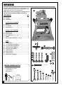
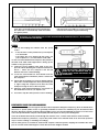
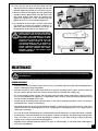
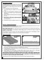
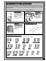
SETUP & OPERATION MANUAL
FEATURES
7” MOLDER
Cast-iron table and head for smooth vibration free performance.
Heavy-duty cast-iron dovetailed column,
precision machined for smooth cutter
head height adjustment.
Precision high-speed, sealed,
pre-lubricated bearings.
Independent, variable speed feed motor
provides added control for precision, tearout free performance with hardwoods and
stock with figured grain.
Jackscrew style cutter head adjustment
system.
Triple guide bearing design allows for
curved moldings
Easily adjustable guide fence system; simple lock knob design, to keep stock in-line
through the cut.
In-feed and out-feed table extension
rollers, for added support with longer workpieces.
Magnetic 2-step safety switch to prevent
unwanted or unintentional start-up is
equipped with an extra-large easy access
stop panel and a lock-out key to prevent
unauthorized use of the molder.
Built-in dust hood with 4” dust outlet.
Variable feed speed.
SPECIFICATIONS
MAXIMUM PLANING WIDTH
7” (178 MM)
MAXIMUM MOLDING WIDTH
6 3⁄4” (171 mm)
MAXIMUM THICKNESS OF STOCK
8” (203 mm)
MINIMUM THICKNESS OF STOCK
1⁄4” (6 mm)
MINIMUM LENGTH OF STOCK
8” (203 mm)
MAXIMUM DEPTH OF CUT (PLANING)
1⁄8” (3 mm)
MAXIMUM DEPTH OF CUT (MOLDING)
3⁄4” (19 MM)
NUMBER OF KNIVES
2
CUTTER HEAD SPEED
7000 RPM
FEED SPEED (VARIABLE)
3 - 20 FPM (0.9 - 6.1 MPM)
MOTOR
2 HP 220 V, 1 PH, 12 A
OVERALL DIMENSIONS (L X W X H)
32” X 27 1⁄2” X 51” (813 X 699 X 1295 MM)
WEIGHT
242 LBS (110 KG)
MODEL
#30-120 M1
REVISION 1 - MARCH 08/10
© Copyright General® International 03/2010
GENERAL® INTERNATIONAL
8360 Champ-d’Eau, Montreal (Quebec) Canada H1P 1Y3
Telephone (514) 326-1161 • Fax (514) 326-5555 • www.general.ca
THANK YOU
for choosing this General® International model 30-120 M1
7” Molder. This molder has been carefully tested and inspected before shipment and if
properly used and maintained, will provide you with years of reliable service. For your safety,
as well as to ensure optimum performance and trouble-free operation, and to get the most
from your investment, please take the time to read this manual before assembling, installing
and operating the unit.
The manual’s purpose is to familiarize you with the safe operation, basic function, and features
of this molder as well as the set-up, maintenance and identification of its parts and components. This manual is not intended as a substitute for formal woodworking instruction, nor to
offer the user instruction in the craft of woodworking. If you are not sure about the safety of
performing a certain operation or procedure, do not proceed until you can confirm, from
knowledgeable and qualified sources, that it is safe to do so.
Once you’ve read through these instructions, keep this manual handy for future reference.
Disclaimer: The information and specifications in this
manual pertain to the unit as it was supplied from the
factory at the time of printing. Because we are committed to making constant improvements, General®
International reserves the right to make changes to
components, parts or features of this unit as deemed
necessary, without prior notice and without obligation to
install any such changes on previously delivered units.
Reasonable care is taken at the factory to ensure that
the specifications and information in this manual corres-
ponds with that of the unit with which it was supplied.
However, special orders and “after factory” modifications may render some or all information in this manual
inapplicable to your machine. Further, as several generations of this model of molder and several versions of
this manual may be in circulation, if you own an earlier
or later version of this unit, this manual may not depict
your machine exactly. If you have any doubts or questions contact your retailer or our support line with the
model and serial number of your unit for clarification.
GENERAL® & GENERAL® INTERNATIONAL WARRANTY
All component parts of General®, General® International and Excalibur by General
International ® products are carefully inspected during all stages of production and each unit
is thoroughly inspected upon completion of assembly.
Limited Lifetime Warranty
Because of our commitment to quality and customer satisfaction, General® and General®
International agree to repair or replace any part or component which upon examination,
proves to be defective in either workmanship or material to the original purchaser for the life
of the tool. However, the Limited Lifetime Warranty does not cover any product used for professional or commercial production purposes nor for industrial or educational applications. Such
cases are covered by our Standard 2-year Limited Warranty only. The Limited Lifetime Warranty
is also subject to the “Conditions and Exceptions” as listed below.
Standard 2-Year Limited Warranty
All products not covered by our lifetime warranty including products used in commercial,
industrial and educational applications are warranted for a period of 2 years (24 months) from
the date of purchase. General® and General® International agree to repair or replace any
part or component which upon examination, proves to be defective in either workmanship or
material to the original purchaser during this 2-year warranty period, subject to the “conditions
and exceptions” as listed below.
To file a Claim
To file a claim under our Standard 2-year Limited Warranty or under our Limited Lifetime
Warranty, all defective parts, components or machinery must be returned freight or postage
prepaid to General® International, or to a nearby distributor, repair center or other location
designated by General® International. For further details call our service department at 1-888949-1161 or your local distributor for assistance when filing your claim.
Along with the return of the product being claimed for warranty, a copy of the original proof
of purchase and a “letter of claim” must be included (a warranty claim form can also be used
and can be obtained, upon request, from General® International or an authorized distributor)
clearly stating the model and serial number of the unit (if applicable) and including an explanation of the complaint or presumed defect in material or workmanship.
CONDITIONS AND EXCEPTIONS:
This coverage is extended to the original purchaser only. Prior warranty registration is not
required but documented proof of purchase i.e. a copy of original sales invoice or receipt
showing the date and location of the purchase as well as the purchase price paid, must be
provided at the time of claim.
Warranty does not include failures, breakage or defects deemed after inspection by General®
or General® International to have been directly or indirectly caused by or resulting from;
improper use, or lack of or improper maintenance, misuse or abuse, negligence, accidents,
damage in handling or transport, or normal wear and tear of any generally considered consumable parts or components.
Repairs made without the written consent of General® Internationallwill void all warranty.
TABLE OF CONTENTS
Rules for safe operation . . . . . . . . . . . . . . .5
Electrical requirements . . . . . . . . . . . . . . .6
Grounding instructions . . . . . . . . . . . . . . . . . . . . . . .6
Circuit capacity . . . . . . . . . . . . . . . . . . . . . . . . . . . . .6
Extension cords . . . . . . . . . . . . . . . . . . . . . . . . . . . . .6
Identification of main parts
and components . . . . . . . . . . . . . . . . . . . .7
Checking/Setting the knives for planing
13-15
Setting one knife parallel to the table . . . . . . . . .14
Setting the height of the second knife . . . . . . . . .15
Adjusting the feed rollers . . . . . . . . . . .16-17
Adjusting the feed roller height . . . . . . . . . . . . . . .16
Adjusting the feed roller pressure . . . . . . . . . . . . .17
To install molding knives . . . . . . . . . . . . .18
Operating instructions . . . . . . . . . . . . .20-24
Unpacking . . . . . . . . . . . . . . . . . . . . . . . . .8
List of contents . . . . . . . . . . . . . . . . . . . . . . . . . . . . . .8
Additional requirements for set up . . . . . . . . . . . . .8
Placement within the shop /
Establishing a safety zone . . . . . . . . . . . . .9
Basic principles of planing/molding . . . . . . . . . .20
Selecting boards suitable for planing/molding .20
Rated limits of this molder/planer . . . . . . . . . . . . .20
Connecting to a dust collector . . . . . . . . . . . . . . .21
Checklist before starting . . . . . . . . . . . . . . . . . . . . .21
Planing . . . . . . . . . . . . . . . . . . . . . . . . . . . . . . . . . . .22
Molding . . . . . . . . . . . . . . . . . . . . . . . . . . . . . . . . . . .23
Repeat/multiple passes (for planing & molding) .23
Molding curved pieces using the elliptical jig . .24
Preparation & Clean up . . . . . . . . . . . . . . . .9
Install the cutter head height adjustment
handwheel . . . . . . . . . . . . . . . . . . . . . . . . . . . . . . . . .9
Remove the styrofoam block . . . . . . . . . . . . . . . . . .9
Remove the protctive plastic sheet . . . . . . . . . . . . .9
Clean up . . . . . . . . . . . . . . . . . . . . . . . . . . . . . . . . . .10
Maintenance . . . . . . . . . . . . . . . . . . . .25-19
Periodic maintenance . . . . . . . . . . . . . . . . . . . . . .25
Drive chain/gear lubrication . . . . . . . . . . . . . . . . .26
Inspecting/replacing cutte head knives . . . . . . .26
Recommended optional accessories . . . . .27
Assembly instructions . . . . . . . . . . . . . . .10
Mount the magnetic safety switch . . . . . . . . . . . .10
Attach the leveling feet to the stand . . . . . . . . . . .10
Install the belt on the drive pulley . . . . . . . . . . . . .10
Basic adjustments & controls . . . . . . . .11-13
Raising/Lowering the cutter head for
depth of cut . . . . . . . . . . . . . . . . . . . . . . . . . . . . . . .11
Connecting to a power source . . . . . . . . . . . . . . .12
On/off power switches . . . . . . . . . . . . . . . . . . . . . .12
On/off magnetic power switch . . . . . . . . . . . . . . .12
Feed motor switch with safety key . . . . . . . . . . . .12
Thermal relay/circuit breaker . . . . . . . . . . . . . . . .13
Changing feed speed . . . . . . . . . . . . . . . . . . . . . .13
Parts list & diagrams . . . . . . . . . . . . . .28-34
RULES FOR SAFE OPERATION
To help ensure safe operation, please take a moment to learn the machine’s applications and limitations, as well as potential hazards. General® International disclaims any real or implied warranty and holds itself harmless for any injury that
may result from improper use of its equipment.
1. Do not operate this molder when tired, distracted, or
under the effects of drugs, alcohol or any medication
that impairs reflexes or alertness.
13. Do not push or force stock into the cutter head. The
molder will perform better and safer when working at
the rate for which it was designed.
2. The working area should be well lit, clean and free of
debris.
14. Kickback is when the workpiece is ejected at high
speeds by the force of the cutter head. To minimize the
risk of injury from kickback, use proper feeding technique and stand to one side, out of the path of a potential kickback.
3. Keep children and visitors at a safe distance when the
molder is in operation; do not permit them to operate
the molder.
4. Childproof and tamper proof your shop and all machinery with locks, master electrical switches and
switch keys, to prevent unauthorized or unsupervised
use.
5. Stay alert! Give your work your undivided attention.
Even a momentary distraction can lead to serious
injury.
6. Fine particulate dust is a carcinogen that can be
hazardous to health. Work in a well-ventilated area
and whenever possible use a dust collector. Wear
face, eye, ear, respiratory and body protection
devices.
7. Do not wear loose clothing, gloves, bracelets, necklaces or other jewelry while the molder is in operation.
Wear protective hair covering to contain long hair
and wear non-slip footwear.
8. Be sure that adjusting wrenches, tools, drinks and
other clutter are removed from the machine and/or
the table surface before operating.
9. Keep hands well away from knives and all moving
parts. Use a push stick to feed stock, and a brush, not
hands, to clear away chips and dust.
10. Be sure that the knives are securely installed in the
cutter head.
11. Always use clean, properly sharpened knives. Dirty or
dull knives are unsafe and can lead to accidents.
12. Inspect stock and remove all foreign objects before
planing. Make sure that any stock you plane is clean
and free of any dirt, nails, staples, tiny rocks or any other
foreign objects that may damage the molder knives.
Only process natural solid wood boards. Never plane
MDF, particle board, plywood, laminates or other synthetic materials.
15. Select appropriate feed speed for the stock being
planed: high speed for softwood and slow for hardwoods.
16. Place stock firmly against the table and use suitable
in-feed and out-feed support if stock is too long.
17. Keep guards in place and in working order. If a guard
must be removed for maintenance or cleaning make
sure it is properly attached before using the machine
again.
18. Use of parts and accessories NOT recommended by
GENERAL®INTERNATIONAL may result in equipment
malfunction or risk of injury.
19. Never stand or lean on machinery. Serious injury could
result if the tool is tipped over or if the cutting tool is unintentionally contacted.
20. Always disconnect the tool from the power source
before servicing or changing accessories such as
knives, or before performing any maintenance or
cleaning, or if the machine will be left unattended.
21. Make sure that the switch is in the “OFF” position before
plugging in the power cord.
22. Make sure the tool is properly grounded. If equipped
with a 3-prong plug it should be used with a three-pole
receptacle. Never remove the third prong.
23. Do not use this molder for other than its intended use.
If used for other purposes, GENERAL® INTERNATIONAL
disclaims any real implied warranty and holds itself
harmless for any injury, which may result from that use.
5
ELECTRICAL REQUIREMENTS
BEFORE CONNECTING THE MACHINE TO THE POWER SOURCE, VERIFY THAT THE VOLTAGE OF YOUR POWER SUPPLY CORRESPONDS
WITH THE VOLTAGE SPECIFIED ON THE MOTOR I.D. NAMEPLATE. A POWER SOURCE WITH GREATER VOLTAGE THAN NEEDED CAN
RESULT IN SERIOUS INJURY TO THE USER AS WELL AS DAMAGE TO THE MACHINE. IF IN DOUBT, CONTACT A QUALIFIED ELECTRICIAN
BEFORE CONNECTING TO THE POWER SOURCE.
THIS TOOL IS FOR INDOOR USE ONLY. DO NOT EXPOSE TO RAIN OR USE IN WET OR DAMP LOCATIONS.
EXTENSION CORDS
C
A
B
GROUNDING INSTRUCTIONS
In the event of an electrical malfunction or short circuit,
grounding reduces the risk of electric shock to the operator. The motor of this machine is wired for 220V single
phase operation and is equipped with a 3-conductor
cord A and a 3-prong grounded plug B to fit a matching grounding type receptacle C.
The use of an extension cord is not generally recommended for 220V equipment. If you find it necessary,
use only 3-wire extension cords that have 3-prong
grounding plug and a matching 3-pole receptacle that
accepts the tool’s plug. Repair or replace a damaged
extension cord or plug immediately.
If you find it necessary to use an extension cord with
your machine make sure the cord rating is suitable for
the amperage listed on the motor I.D. plate. An undersized cord will cause a drop in line voltage resulting in
loss of power and overheating. The accompanying
chart shows the correct size extension cord to be used
based on cord length and motor I.D. plate amp rating.
If in doubt, use the next heavier gauge. The smaller the
number, the heavier the gauge.
TABLE - MINIMUM GAUGE FOR CORD
TOTAL LENGTH OF CORD IN FEET
AMPERE
RATING
<5
DO NOT MODIFY THE PLUG PROVIDED ! If it will not fit your recepta-
cle, have the proper receptacle installed by a qualified electrician.
CHECK with a qualified electrician or service person if
you do not completely understand these grounding
instructions, or if you are not sure the tool is properly
grounded.
CIRCUIT CAPACITY
Make sure that the wires in your circuit are capable of
handling the amperage draw from your machine, as
well as any other machines that could be operating on
the same circuit. If you are unsure, consult a qualified
electrician. If the circuit breaker trips or the fuse blows
regularly, your machine may be operating on a circuit
that is close to its amperage draw capacity. However, if
an unusual amperage draw does not exist and a
power failure still occurs, contact a qualified technician
or our service department.
6
6 TO 10
10 TO 12
12 TO 16
220 VOLTS 25 FEET
------->
------->
------->
------->
50 FEET
100 FEET 150 FEET
18
AWG
16
16
14
18
16
14
12
16
16
14
12
14
12
* NR
* NR
* NR = Not Recommended
7” MOLDER
30-120 M1
IDENTIFICATION OF MAIN PARTS AND COMPONENTS
A
C
B
D
F
G
G
E
E
I
H
J
M
k
L
N
O
A- CUTTER HEAD HEIGHT ADJUSTMENT HANDWHEEL
H- FEED SPEED CONTROL KNOB
B- BELT COVER
J- THERMAL RELAY
C- DUST HOOD
K- DRIVE MOTOR
D- FEED MOTOR
L- MAGNETIC SWITCH WITH LOCK-OUT KEY
E- TABLE EXTENSION ROLLERS
M- DRIVE MOTOR COVER PANEL
F- FENCES
N- STAND
G- FENCE LOCK KNOBS
O- LEVELING FOOT
I- FEED MOTOR SWITH WITH SAFETY KEY
7
UNPACKING
Carefully unpack and remove the molder and its components from the box and check for damaged or missing items as per the list of contents below.
NOTE: Please report any damaged or missing items to
your General International distributor immediately.
LIST OF CONTENTS
A
QTY
A- MOLDER .........................................................................1
B- HANDWHEEL ..................................................................1
LEVELING FOOT & HARDWARE:
C - HEX NUT .........................................................................8
D - FLAT WASHER ............................................... .................8
E - LEVELING FOOT .............................................................4
ELLIPTICAL JIG & HARDWARE:
FGHIJ-
ELLIPTICAL JIG................................................................1
IDLER BEARING ..............................................................1
CAP SCREW M8 X 1.25 - 110L .....................................2
WASHER..........................................................................2
BUTTON HEAD SCREW M6 X 1.0 - 16L. ........................2
TOOLS
KLMNOPQRS-
SCREWDRIVER ...............................................................1
17-19 MM OPEN END WRENCH ..................................1
12-14 MM OPEN END WRENCH ..................................1
7-8 MM OPEN END WRENCH ......................................1
6 MM OPEN END WRENCH .........................................1
6 MM ALLEN KEY ..........................................................1
4 MM ALLEN KEY ..........................................................1
2 MM ALLEN KEY ...........................................................1
4 MM T-HANDLE WRENCH.............................................1
B
F
C
H
G
D
C
E
I
J
ADDITIONAL REQUIREMENTS FOR SET UP
• Extra person for help with lifting
• Feeler gauge set (0.030”)
• 3 mm Allen key
• Gauge block
K
L
M
T
N
O
P
8
Q
R
PLACEMENT WITHIN THE SHOP / ESTABLISHING A SAFETY ZONE
THIS MODEL 30-120 M1 7” MOLDER IS HEAVY. DO NOT OVER-EXERT. THE HELP OF AT LEAST ONE ASSISTANT OR A HOIST WILL BE
NEEDED FOR THE FOLLOWING STEP.
TO LIMIT THE RISK OF SERIOUS INJURY OR DAMAGE TO THE MACHINE, ANY EQUIPMENT USED TO LIFT THIS MACHINE SHOULD HAVE
A RATED CAPACITY IN EXCESS OF 242 LBS (110 KG).
PLACEMENT WITHIN THE SHOP
This machine should be installed and operated only on
a solid, flat and stable floor that is able to support the
weight of the molder and the operator. Using the dimensions shown as a guideline, plan for placement within
your shop that will allow the operator to work unencumbered and unobstructed by foot traffic (either passing
shop visitors or other shop workers) or other tools or
machinery.
51”
32”
ESTABLISHING A SAFETY ZONE
For shops with frequent visitors or multiple operators, it is
advisable to establish a safety zone around shop
machinery. A clearly defined “no-go” zone on the floor
around each machine can help avoid accidents that
27 1/2 ”
could cause injury to either the operator or the shop visitor. It is advisable to take a few moments to either paint
(using non-slip paint) or using tape, define on the floor the limits or perimeter of each machines safety zone. Take
steps to ensure that all operators and shop visitors are aware that these areas are off limits whenever a machine is
running for everyone but the individual operating the unit.
PREPARATION & CLEAN UP
INSTALL THE CUTTER HEAD HEIGHT ADJUSTMENT HANDWHEEL
A
REMOVE THE STYROFOAM BLOCK
B
D
C
E
To limit the potential for damage in transport, this molder is shipped from the factory with the molder’s head sitting on a styrofoam block for support.
1. Using a 3 mm Allen key, loosen the set screw A on
the handwheel.
2. Fit the handwheel shaft onto the shaft, B.
3. Tighten the set screw C to secure the handwheel in
place.
1. Loosen the cutter head lock lever D by turning it
counterclockwise. Important! Attempting to adjust the
height of the cutter head with it’s lock lever tightened
will cause premature wear of the locking mechanism.
2. Rotate the handwheel counterclockwise to raise
the cutter head enough to remove the styrofoam
block E.
REMOVE THE PROTECTIVE PLASTIC SHEET
1. Loosen the fence lock knobs F and remove the
fences G and H.
2. Remove the protective plastic sheet I from the
table.
H
G
F
I
9
CLEAN UP
The protective coating on the table, K, prevents rust
from forming during shipping and storage. Remove it
by rubbing with a rag dipped in kerosene, mineral
spirits or paint thinner.
K
Important: Dispose of potentially flammable solventsoaked rags according to manfacturer’s safety recommendations.
A putty knife, held flat to avoid scratching the surface,
may also be used to scrape off the coating followed by
clean-up with solvent.
Note: Avoid rubbing the molder’s painted surfaces, as many
solvent-based products will remove paint.
Tip: To prevent rust, apply a light coating of paste wax
or use regular applications of any after-market surface
protectant or rust inhibitor.
ASSEMBLY INSTRUCTIONS
For your convenience this molder is shipped from the factory partially assembled and requires only minimal assembly and set up before being put into service.
MOUNT THE MAGNETIC SAFETY SWITCH
B
SERIOUS PERSONAL INJURY COULD OCCUR
IF YOU CONNECT THE MACHINE TO THE
POWER SOURCE BEFORE YOU HAVE COMPLETED THE INSTALLATION AND ASSEMBLY
STEPS. DO NOT CONNECT THE MACHINE TO
THE POWER SOURCE UNTIL INSTRUCTED TO
DO SO.
A
Attach the magnetic safety swith to the right side of the
molder using the 2 button head screws already
mouned to the stand A as shown in B.
ATTACH THE LEVELING FEET TO THE STAND
INSTALL THE BELT ON THE DRIVE PULLEY
CLOSE UP
B
C
A
E
D
Attach the 4 leveling feet A to the stand using 2 nuts
B and 2 washers C in the assembly order shown in D.
Note: After the stand is placed in its final location, level
the feet by loosening the top nut, adjusting lower nut up or
down on the screw stem as needed, then tightening down
the top nut.
10
E
Note: To limit the potential for damage in transport, this
molder is shipped from the factory with the motor mounting plate secured to the stand with a cap screw E.
1. Using the supplied 6 mm allen key, loosen and
remove the cap screw and flat washer E that secures the motor mounting plate to the stand.
H
F
F
I
G
I
I
I
F
2. Using the supplied 4 mm T-handle wrench, loosen
and remove the 3 Allen screws F, then remove the
upper pulley cover G.
3. Using the supplied 4 mm T-handle wrench,
unscrew and remove the 4 button head screws I
that secure the motor cover panel to the stand.
Note: The drive belt is already installed on the upper
pulley H .
J
K
4. Remove the motor cover panel to access the
motor J.
5. With the help of an assistant, lift the motor up and
install the other end of the belt in the slot on the
lower pulley K.
6. Re-install the motor cover panel and upper pulley cover.
BASIC ADJUSTMENTS & CONTROLS
RAISING/LOWERING THE CUTTER HEAD FOR DEPTH OF CUT
The depth of cut is set by raising or lowering the cutter head.
B
DOWN
UP
C
A
A
1/3 x
1.
= 1/32”
Loosen the cutter head lock lever A by turning it
counterclockwise.
Important! Attempting to adjust the height of the cutter
head with it’s lock lever tightened will cause premature
wear of the locking mechanism.
2. Use handwheel B to adjust the cutter head height to
the desired depth of cut, turning:
- Clockwise to raise the cutter head.
- Counterclockwise to lower the cutter head.
Note: the depth gauge, C, on the front of the machine can
be used as a reference but it is not intended for high precision measurements
3. Re-tighten lock lever A to secure the cutter head in
position.
NOTE: 1/3 of a clockwise rotation of the crank handle
will raise the cutter head by 1/32”. 1/3 of a counterclockwise rotation will lower the cutter head by 1/32”.
11
CONNECTING TO A POWER SOURCE
TO REDUCE THE RISK OF SHOCK OR FIRE
DO NOT OPERATE THE UNIT WITH A DAMAGED POWER CORD OR PLUG. REPLACE
DAMAGED CORD OR PLUG IMMEDIATELY.
SWITCHES OFF
TO AVOID UNEXPECTED OR UNINTENTIONAL START-UP, MAKE SURE THAT BOTH OF
THE POWER SWITCHES ARE IN THE OFF
POSITION BEFORE CONNECTING TO A
POWER SOURCE.
Once the assembly steps have been completed, uncoil the power cord and plug the power cord into an appropriate outlet. Refer back to the section entitled “Electrical Requirements” and make sure all requirements and grounding
instructions are followed. When operations have been completed unplug the molder from the power source.
ON/OFF POWER SWITCHES
This molder is equipped with 2 different ON/OFF power switches: one magnetic switch equipped with a lock-out key for
the drive motor and one independant on/off switch with a safety key and thermal /re-set breaker for the feed motor.
TO PREVENT UNAUTHORIZED USE OR UNINTENTIONAL START-UP, REMOVE THE SAFETY KEY AND LOCK-OUT KEY AND
STORE THEM IN A SAFE PLACE, OUT OF THE REACH OF CHILDREN, WHENEVER THE MOLDER IS NOT IN USE.
ON/OFF MAGNETIC POWER SWITCH
This model 30-120 M1 is equipped with a Magnetic 2-step
safety switch to prevent unwanted or unintentional
start-up and unauthorized use of the planer/molder.
A
The switch assembly is equipped with a GREEN “START” button A, an extra-large easy access RED stop panel B, and
a lock-out key C.
B
C
To start the molder: Insert the lock-out key C and press on
the GREEN “START” button A.
To stop the molder: Press on the RED “STOP” panel, B.
Once the RED “STOP” panel has been pressed, the planer/molder can only be started by pressing once again on
the RED “STOP” panel to release the green button, then by
pressing on the green button.
FEED MOTOR SWITCH WITH SAFETY KEY
G
D
H
F
E
SAFETY KEY*
ON
OFF
This model 30-120 M1 is also equiped with a simple ON / To start the feed motor: insert the safety key F and lift
OFF switch ,D, for the feed motor, featuring a removable the switch up, G.
lock out safety key E.
To stop the feed motor: push down on the switch H.
12
THERMAL RELAY / CIRCUIT BREAKER
TO AVOID UNEXPECTED OR UNINTENTIONAL START-UP BE
CERTAIN THAT THE SWITCH HAS BEEN SET TO THE OFF
POSITION BEFORE RE-SETTING THE THERMAL RELAY.
SWITCH OFF
The thermal relay (circuit breaker) protects the feed
motor from power surges or spikes in line voltage.
In the event of a power surge, the thermal relay will be
automatically tripped thereby cutting off the power to
the feed motor.
I
To reset the thermal relay after it has been tripped: set
the feed motor switch to the “off” position and press the
thermal relay re-set button I, then restart the feed motor.
CHANGING FEED SPEED
The feed motor speed ranges from 3 to 20 FPM (Feet Per
minute). The feed speed adjustment knob is located on
the feed motor control panel, on the right hand side of the
machine. Turn the knob:
Decrease
speed
Increase
speed
- Clockwise to increase the feed rate.
- Counterclockwise to decrease the feed rate.
Select appropriate feed speed for the stock being
planed/molded: high speed for softwood and slow for
hardwoods. Experiment with feed speeds based on the
workpiece material and its width as well as the depth of
cut, to find which setting work best for your needs. As a general guideline however, for best results more aggressive
cuts or wider materials should be planed at slower speeds and lighter cuts or narrow materials can be planed at
higher speeds.
CHECKING / SETTING THE KNIVES FOR PLANING
Accurate results can only be achieved when the two knives are properly installed and set to the exact same height in the
cutter head.
The planer knives have been factory set to the exact same height in the cutter head. However we suggest that you verify the knives prior to first use. To verify if the knives are set properly, use a gauge block* (not included) following the steps
below for each knives:
*Gauge block
You may use a home made gauge block made of
hardwood. The gauge block can be made by following the dimensions in A.
A
If you prefer, precision aluminum gauge blocks
are available from General International under
item #30-040.
13
ALWAYS DISCONNECT THE MACHINE FROM THE POWER SOURCE BEFORE MAKING ANY ADJUSTMENTS. FAILURE
TO HEED THIS WARNING CAN LEAD TO SERIOUS PERSONAL INJURY.
KNIVES ARE VERY SHARP. USE CARE WHEN HANDLING KNIVES.
B
C
D
C
C
1. Make sure that the the machine is disconnected from
the power source.
3. Turn the upper pulley D by hand, until any one of
the knives is at it’s lowest point.
2. To give yourself unimpeded access to the cutter head
and knives, remove the top cover B, by loosening and
removing the 3 screws C.
E
F
H
DOWN
UP
G
4. Place your gauge block onto the table, under one
extremity of the cutter head as shown in E and F.
SETTING ONE KNIFE PARALLEL TO THE TABLE
5.
Loosen the cutter head lock lever G by turning it
counterclockwise, then lower or raise the cutter
head as needed until the knife lightly touches the
top of the gauge block as shown in H when you
manually rock the cutter head back and forth.
6.
Tighten the cutter head lock lever G to secure the
cutter head in position.
UNDERSIDE VIEW
I
7. Place your gauge block onto the table, under the
other extremity of the cutter head to check for knife
parallelism with the table.
Should the knife not be set properly follow next steps. If
the knife is parallel to the table, skip ahead to step 15.
14
J
8. Turn the upper pulley by hand until you can fit the
supplied T-handle wrench into the holes in the cutter head shaft as shown in I and J to keep the
cutter head from turning.
M
K
N
N
L
9. Loosen the 3 button head screws K using the supplied
4 mm T-handle wrench and draw the chip deflector
away L from the cutter head as shown, then secure it in
position.
11. Loosen the nut O located on top of the knife (the one
on the side of the knife that need to be adjusted),
then adjust the set screw P to raise or lower the knife
until it lightly touches the top of the gauge block.
12. Re-tighten nut O then re-check the height setting on
the other extremity of the knife and re-set if necessary until the knife is parallel to the table.
10. Fully loosen the 2 middle locking bolts M using the
supplied 14 mm wrench, then slightly loosen the
end locking bolts N, so that they still hold the knife.
P
O
13. Re-tighten the locking bolts M and N.
SETTING THE HEIGHT OF THE SECOND KNIFE
UNDERSIDE VIEW
14. Remove the T-handle wrench from the cutter head,
rotate the head 180° and re-install the wrench to
lock the opposite side of head in place.
15. Place your gauge block onto the table, under one
extremity of the second knife. If the second knife is
set higher or lower than the first knife, follow steps
10 and 11.
16. Place your gauge block under the other extremity of
second knife and check for knife parallelism with the
table.
Should the knife not be set properly follow steps 11 to
13.
If the second knife is parallel to the table, re-tighten nut
O and locking bolts M and N.
15
ADJUSTING THE FEED ROLLERS
ADJUSTING THE FEED ROLLER HEIGHT
The feed rollers have been factory set at 0.030" below the lowest point of the knives. However we recommend that you
verify that the feed rollers are properly set prior to first use.
Important! Always verify that the two knives are properly installed and set to the exact same height in the cutter head before
checking and adjusting the height of the feed rollers.
FAILURE TO FOLLOW THESE RECOMMENDATIONS WILL LEAD TO POTENTIAL SERIOUS INJURY
CAUSED BY STOCK KICKBACK.
Make sure that the feed rollers are set 0.030 inches below the lowest point of the cutter knives as
shown in A so that they can “grip” the board. If the feed rollers are set higher than the lowest point
of the knives as shown in B, they won’t be able to grip the workpiece which will be ejected at high
speeds by the force of the cutter head.
cutter head
A
Out-feed roller
B
In-feed roller
0.030"
ALWAYS DISCONNECT THE MACHINE FROM THE POWER SOURCE BEFORE MAKING ANY ADJUSTMENTS. FAILURE
TO HEED THIS WARNING CAN LEAD TO SERIOUS PERSONAL INJURY.
TO LIMIT THE POTENTIAL FOR INJURY FROM A KICKBACK, ALWAYS MAKE SURE THAT THE FEED ROLLERS ARE SET
LOWER THAN THE LOWEST POINT OF THE CUTTER HEAD BEFORE ENGAGING A BOARD IN THE CUTTER HEAD.
C
D
E
Out-feed roller
16
In-feed roller
1. Place your gauge block on the table, under the cutter head.
3. Tighten the cutter head lock lever to secure the
cutter head in position.
2. Place a 0.030" feeler gauge C on top of the gauge
block, then lower the cutter head until the knife lightly touches the feeler gauge D when manually rocking the cutter head back and forth.
4. Place your gauge block on the table, under the infeed roller E.
Out-feed
roller
F
G
In-feed
roller
H
I
5. If needed, adjust the height of the in-feed roller by
loosening the lock nuts F on the in-feed roller adjustment screws H and then turning adjustment screws
G until the in-feed roller lightly touches the top of
the gauge block, then re-tighten lock nuts F.
6. Place your gauge block onto the table, under the outfeed roller. If needed, adjust the height of the outfeed roller by loosening the lock nuts on the outfeed roller adjustment screws I and then turning the
adjustment screws until the out-feed roller lightly
touches the top of the gauge block, then re-tighten
the lock nuts.
Note: To avoid overtensionning the drive chains, which may result in drive chain breakage, do not lower the feed rollers too
much. Use the number of threads on the adjustment screws as a visual reference. You should not count more than 5 threads
on theses screws. If you have lowered the feed rollers to their lowest point and they still do not touch the top of the gauge
block, you then will have to adjust the depth of cut to remove the thickness of material equivalent to the distance between
the feed rollers and gauge block when the rollers are adjusted to their lowest point.
FOR EXTENDED FEED ROLLER LIFE
The infeed and outfeed rollers will have to be lowered for most molding operations. The amount of adjustment
required will vary depending on the size and style of the cutter. For larger profiles and deeper cuts, re-adjust the
height of the feed rollers after a few passes by loosening the screws G 2 turns (approx.) to correct the height of the
rollers vs the depth of the stock that was removed from the workpiece.
To prevent the top of the workpiece from damaging the feed rollers make sure that the workpiece never exceed 1/4"
of the height of the rollers J.
J
Out-feed
roller
In-feed
roller
3/4
1/2
1/4
Make sure the feed rollers are never set
lower than this point
ADJUSTING THE FEED ROLLER PRESSURE
The feed rollers are factory set to provide a proper amount
of downward pressure to the workpiece. However we recommend that you verify that the feed rollers are properly
set prior to first use.
K
M
L
Then, with use and normal wear over time, it may periodically become necessary to make minor adjustments to
pressure of the feed rollers.
If you notice snipe (which is a small depression in the surface of a workpiece across its width either at one or both ends of your workpiece, the pressure on the feed rollers
must be reduced.
Refer to the following symptoms to determine which roller need to be adjusted:
- If snipe occurs at the beginning of the board, reduce the amount of pressure on the in-feed roller by turning
lock nut K on adjusting screws L counterclockwise.
- If snipe occurs at the tail end of the board, reduce the amount of pressure on the out-feed roller by turning
the lock nut K on adjusting screws M counterclockwise.
NOTE: Some experimentation may be necessary to achieve an ideal adjustment.
17
TO INSTALL MOLDING KNIVES
ALWAYS DISCONNECT THE MACHINE FROM THE POWER SOURCE BEFORE CHANGING KNIVES OR MAKING ANY
ADJUSTMENTS. FAILURE TO HEED THIS WARNING CAN LEAD TO SERIOUS PERSONAL INJURY.
KNIVES ARE VERY SHARP. USE CARE WHEN HANDLING KNIVES.
UNDERSIDE VIEW
A
B
C
B
D
B
1. Make sure that the the machine is disconnected
from the power source.
2. To give yourself unimpeded access to the cutter
head and knives, remove the top cover A, by loosening and removing the 3 screws B.
3. Turn the upper pulley by hand until you can fit the
supplied T-handle wrench into the holes in the cut
ter head shaft as shown in C and D to keep the cut
ter head from turning while changing knives.
F
E
E
E
E
4. Using the supplied 14 mm wrench, loosen and
remove all 4 locking bolts E.
5. Carefully remove the knife F.
6. Repeat steps 4 and 5 with the second knife on the
opposite side of the cutter knife.
H
G
I
J
7. Clean any dust or wood chips from the cutter head
G and knives, and carefullly store the knives in
a safe and dry place if they will be re-used, or dispose of them safely if they are worn or damaged.
18
BEFORE INSTALLING MOLDING KNIVES, MAKE SURE THAT
THE SET SCREWS DO NOT PROTRUDE FROM THE INNER
FACE OF THE CUTTER HEAD AS SHOWN IN H (LETTER I
SHOWS A PROTRUDING SET SCREW) AND THAT THE NUTS
ARE FIRMLY FASTENED SO THAT THE KNIVES SIT FLUSH
ONTO THE LIP. FAILURE TO HEED THIS WARNING CAN
RESULT IN SERIOUS INJURIES AND/OR DAMMAGE TO THE
MACHINE.
8. Place the molding knife against the cutter head lip
with the beveled side of the knife facing up, J.
K
L
9. Use the holes in the cutter head that allow the knife to
be installed as close to center as possible K and
secure the knife in place with a bolt L in each of the
mounting holes in the knife.
Make sure the knife is sitting flush against the bottom
lip and while tightening the bolts, apply light outward
pressure against the knife to push it towards the pulley.
10. Place a perfectly squared block of wood (approx.
1” x 1” x 5”) on the table and against the right fence.
11. With the head positioned low enough, move the
fence and the block over until the block touches
the side of the knife and then lock the fence in
place using both lock knobs.
UNDERSIDE VIEW
P
O
12. Remove the T-handle wrench from the cutter head,
rotate the head 180° and re-install the wrench to
lock the opposite side of head in place.
13. Install the second molding knife using the same procedure in corresponding holes in the opposite side of
the head.
14. To ensure that the second knife is aligned with the
first, rotate the head 180° and verify that the side of
knife lightly rubs against the block O. If needed,
loosen the bolts P slightly and apply inward or outward pressure to the knife to reposition it as needed
while retightening the bolts.
L
J
H
K
1/8”
Min.
1/4”
I
K
H
15. Loosen the 3 button head screws H on the flat chip
deflector, then draw the chip deflector towards the
cutter head I so there’s a space of roughly 1/8”
between the chip deflector and knife edges J.
16. Rotate the head 180°
17. Loosen the 2 button head screws K on the curved
chip deflector, then draw the chip deflector towards the cutter head so there’s a minimum
space of 1/4” between the chip deflector and
knife edges J.
19
OPERATING INSTRUCTIONS
BASIC PRINCIPLES OF PLANING / MOLDING
A
This planer/molder is designed to remove material from
the top face of a board in order to bring the board (or a
series of boards) down to a specific desired shape or profile and thickness.
To obtain uniform results across the length of a board, the
stock being planed/molded must have one face that
has already been machined perfectly flat (usually on a
jointer) and the stock should be fed with this flat face
against the table, A.
SELECTING BOARDS SUITABLE FOR PLANING / MOLDING
FLAT SIDE DOWN
B
ALWAYS PLANE / MOLD IN THE GENERAL DIRECTION OF
THE GRAIN. PLANING/MOLDING AGAINST THE GRAIN OR
PLANING END GRAIN IS DANGEROUS AND MAY CAUSE
THE WORKPIECE TO SHATTER.
This planer/molder is intended for use with solid woods or
MDF only, and should not be used to plane or mold any
other materials.
The workpiece should always be fed through the machine in the general direction of the grain in the wood, B.
Before being fed through the planer/molder all lumber should be inspected for debris and foreign objects such as
staples or nails. Foreign objects stuck to, or embedded in your workpiece can be ejected from the machine at high
speed and cause serious injury or damage cutter knives. Make sure to remove all such foreign objects from the
wood before running it through the planer/molder.
Select lumber carefully and avoid workpieces with loose or protruding knots. Workpieces that are twisted, severely
deformed or warped should also be avoided. Warped, twisted, damaged or fragile stock runs an increased risk of
jamming in or damaging the machine or cutters. There is also a much greater risk of injury to the operator or
bystanders from kickback, where the workpiece is forcefully or violently ejected from the machine due to a jam,
whenever working with such damaged or warped wood.
RATED LIMITS OF THIS MOLDER / PLANER
RESPECT THE RATED LIMITS OF THIS MACHINE IGNORING THESE LIMITS AND FEEDING NON COMPATIBLE STOCK
INTO THIS MOLDER/PLANER CAN LEAD TO SERIOUS INJURY TO THE USER OR SHOP BYSTANDERS, AND CAUSE
DAMAGE TO THE WORKPIECE AND/OR THE MACHINE. IF THE STOCK YOU WISH TO PLANE/MOLD DOES NOT MEET
OR COMPLY WITH THE LIMITATIONS LISTED ABOVE, FIND ANOTHER SAFER WAY TO PERFORM THE REQUIRED TASK.
MAXIMUM PLANING WIDTH: 7”.
MAXIMUM MOLDING WIDTH: 6 3/4”.
MAXIMUM WORKPIECE THICKNESS: 8”
MINIMUM THICKNESS TO WHICH A WORKPIECE CAN BE SAFELY PLANED/MOLDED: 1/4”
MINIMUM WORKPIECE LENGTH THAT CAN BE SAFELY PLANED: 8”.
20
MAXIMUM DEPTH OF CUT
It is recommended that for both hard and soft wood:
Removing less material per pass and taking multiple
passes is always preferred to more aggressive planing/molding.
Advantages include longer blade life, better finish quality (resulting in less time sanding later) and less likelihood of removing too much material causing the workpiece to be too thin for its intended use.
Note: Depth of cut will vary depending on the width of the
workpiece, density/type of wood and moisture content of
the stock.
REFERENCE CHART FOR DEPTH OF CUT SELECTION*
WIDTH
TYPE OF WOOD
1”
Poplar
MOLDING
PLANING
DEPTH OF CUT
1/4” or less 1/8” or less
1”
Red Oak
3/16”or less
1/8” or less
3”
White Pine
3/16” or less
1/8” or less
3”
White Oak
1/8” or less
1/8” or less
6”
Poplar
1/8” or less
1/8” or less
6”
Red Oak
1/16” or less
1/8” or less
*The information in this chart is supplied as a general guideline only.
CONNECTING TO A DUST COLLECTOR
A dust port with a 4” opening is provided to accommodate connection to a dust collector (not included).
Be sure to use appropriate sized hose and fittings (not
included) and check that all connections are sealed
tightly to help minimize airborne dust.
If you do not already own a dust collection system
consider contacting your General® International distributor for information on our complete line of dust
collection systems and accessories or visit our Web Site
at www.general.ca
CHECKLIST BEFORE STARTING
A
VERIFY ALL CHECK POINTS BEFORE STARTING.
FAILURE TO COMPLY CAN RESULT IN SERIOUS
INJURIES.
• Make sure you and any assistants are wearing safe appropriate workshop attire. Roll up long sleeves, secure
long hair and remove any jewelry: watches, rings, bracelets or anything that could become caught in the
moving parts, potentially causing serious injury.
• To reduce the risk of damage to the planer/molder or the workpiece, as well as a potential for personal injury,
after initial set-up as well as before each use, make sure that everything is securely installed and that all fasteners and moving parts on this machine are locked in place before starting the machine.
• Make sure that the knives in the cutter head are properly set as explained in section “Checking/Setting the
knives for planing” or in section “To install molding knives”, depending on the intended use of the machine.
• Make sure that the feed rollers are properly set as explained in section “Adjusting the feed rollers”.
• Make sure the board has been inspected and is suitable for planing/molding as explained in section “Selecting
boards suitable for planing/molding”.
• If multiple boards are to be planed, collect all workpieces together and set them nearby on a table or bench
within easy reach. To limit the potential for injury in the event of a kickback, avoid having to step or reach in
front of the machine to pick up the next workpiece A.
• Make sure to have on safety glasses as well as hearing & respiratory protection at all times when using the
machine.
21
PLANING
B
DOWN
UP
A
1/3 x
1. With the planer turned off, position the workpiece
on the table with the flat face down and the face
to be planed facing up.
2. Position the fences A against each edge of the workpiece, without pinching the workpiece between the
fences – make sure the workpiece can be fed
between the fences without binding.
= 1/32”
Note: the depth gauge, B, can
be used as a reference but it is
not intended for high precision measurements
3. Slide the workpiece up to the cutter head and
using the depth of cut adjustment handwheel,
lower the cutter head as needed to obtain the
desired depth of cut.
4. Set the board aside and tighten the cutter head
locking lever C to lock the cutter head in position.
5. Turn on your dust collector.
ALWAYS TURN ON THE DUST COLLECTOR
BEFORE STARTING THE PLANER / MOLDER.
C
D
E
6. Press the green "ON" button D on the magnetic
switch to start the cutter head motor.
7. Set the feed speed to minimum before starting the
feed motor, then lift the switch E up to start the feed
motor. Gradually increase the speed, until you
reach the desired feeding speed.
KEEP HANDS AWAY FROM THE ROTATING CUTTER HEAD AND FEED ROLLERS. DO NOT FORCE
THE WORKPIECE TOWARDS THE CUTTER HEAD –
LET THE IN-FEED ROLLER FEED THE WORKPIECES.
AVOID HAVING TO STEP OR REACH IN
FRONT OF THE MACHINE.
8. Stand to one side of the machine and set the board
back on the infeed table with the face to be planed facing up, aligning the board laterally so that it
will be fed through the planer in the general direction of the grain
22
TO LIMIT THE POTENTIAL FOR INJURY IN THE
EVENT OF A KICKBACK, AVOID STANDING DIR-ECTLY IN LINE WITH THE FRONT OR BACK OF THE
MACHINE WHENEVER A BOARD IS ENGAGED IN
THE CUTTER HEAD.
9. Slowly slide the workpiece forward until the in-feed
roller “grips” the board. Release the board allowing
the feed roller to automatically feed the board
through the planer.
10. Step to the rear of the machine and recover the
planed board on the table once it has cleared the
out-feed roller and has stopped advancing.
NEVER PUSH, PULL OR OTHERWISE TRY TO MOVE OR RE-POSITION THE WORKPIECE ONCE IT IS IN THE CONTROL
OF THE AUTOMATIC FEED ROLLERS.
MOLDING
1. Turn off and unplug the machine from the power
source.
A
2. - If only the face is to be profiled: Cut your workpiece
to it’s final width.
- If the edges are to be trimmed by the knives: Cut
your workpiece to 1/32" wider than it’s final width.
It is also recommended that all workpieces are planed to
the final mold width and height before setting up the
molder for any given profile.
3. Position the fences against each edge of the workpiece A, without pinching the workpiece between the
fences – make sure the workpiece can be fed
between the fences without binding.
4. Loosen the cutter head lock lever B and lower the
cutter head until the knife barely makes contact with
the workpiece.
5. Check that the workpiece is properly aligned with the
knife and if needed adjust the fence positioning left
or right to align the workpiece, then raise the cutter
head just enough to remove the workpiece.
6. Adjust the cutter head downward by one full turn on
the handwheel to take a 3/32” depth of cut.
MAKE SURE THE PLANER / MOLDER HAS BEEN
TURNED OFF AND UNPLUGGED FROM THE
POWER SOURCE BEFORE PERFORMING ANY
MAINTENANCE.
C
DOWN
UP
B
7. Proceed to steps 5 to 10 of previous section “Planing”.
1/3 x
= 1/32”
REPEAT/MULTIPLE PASSES (FOR PLANING AND MOLDING)
In most cases several passes through the machine will be required to bring the workpiece(s) down to final thickness
dimension or specific profile. In fact, it is generally preferable to remove less material per pass and achieve final
thickness dimension/specific profile by taking multiple passes. This can extend blade life, place less strain on the
motor and provide better workpiece finish quality that will require less time spent sanding later.
Once all the boards have been passed through the machine once, set them aside and turn off the machine.
Measure the workpiece(s) thickness / Inspect the profile, and if more material needs to be removed, repeat the
steps of section “Planing” or “Molding” accordingly.
Take as many passes as needed to achieve final workpiece thickness/profile, stopping the machine after each
pass to reset the cutter head height, as well as the feed rollers height if needed.
23
MOLDING CURVED PIECES USING THE ELLIPTICAL JIG
A
The elliptical jig allows you to mold profiles into the face of
curved workpieces.
Molding curved workpieces generally requires the workpiece to be mounted and secured to a template that
rides against the inner and outer guide bearings of the jig
A.
WORKPIECE
For full width profile cuts, both the workpiece and the template must be of the exact same width as the top of the
profile B.
TEMPLATE
B
Note: this is not required when using a profile that is designed
to cut only a portion of the entire width of the workpiece.
Ideally, templates should be made from 3/4” thick MDF C
and should be made roughly 4” longer than the workpiece at each end D.
4"
4"
The minimum length of curved workpiece that can be
safely molded is 9”.
C
To secure the workpiece to a template, pre-drill and
counter sink mounting holes into the template from below
E. The placement of the mounting holes will depend on
the size of the workpiece and the shape of the curve as
well as the profile and depth of cut required.
3/4"
WORKPIECE
TEMPLATE
D
D
WORKPIECE
TEMPLATE
Use appropriate length flathead woodscrews, screwed
into the workpiece from below to a minimum depth, and
keep the final depth of the intended cut of the profile in
mind to avoid having the molder knife contact the tips of
the screw imbedded into the workpiece as the knives cut
deeper into the workpiece from above F. Also make sure
that the heads of the screws are seated below the countersink in the underside of the template to allow the template to slide flat against the table and avoid damaging
or scratching the tables’ surface with an exposed screw
head G.
E
F
G
ALWAYS EXERCISE EXTREME CAUTION WHEN RE-USING A TEMPLATE FOR A DIFFERENT PROFILE, AS A DIFFERENT
LOCATION OF CUT AND DEPTH OF THE CUT IN THE WORKPIECE MAY REQUIRE RELOCATING THE MOUNTING
SCREWS IN ORDER TO AVOID SCREW TIP CONTACT WITH THE KNIVES FROM ABOVE AS THEY CUT INTO THE WORKPIECE.
1. Turn off and unplug the machine from the power source.
2. If installed, remove the two fences.
3. If needed, raise the cutter head to give yourself unimpeded access to the table.
H
I
J
WORKPIECE
TEMPLATE
24
4. Install the elliptical jig inner guide bearings as
shown using 2 cap screws with washers H and
install the outer idler guide bearing as shown
using 2 button head screws I.
5. To align the guide bearings with the profile knife,
lower the head to lightly pinch the workpiece J.
6. Loosen the jam nut K on the inner guide, turn the
adjustment knob L to align the bearings with the knife
and then tighten the jam nut to secure them in place.
7. With the workpiece flush against the inner guide bearings M, loosen the button head screws N on the outer
idler guide bearing and adjust the bearing flush
against the outside face of the workpiece O. Then
tighten the screws to secure the bearing in place.
K
N
L
8. In preparation for the first pass, raise the cutter head
just enough to remove the workpiece, and then readjust the cutter head downward by one full turn on
the handwheel to take than a 3/32” depth of cut.
BEFORE STARTING THE MACHINE AND FEEDING
THE WORKPIECE INTO THE CUTTER MAKE SURE
THAT THERE IS NO INTERFERENCE IN THE KNIFE
AREA THAT COULD CAUSE THE KNIVES TO MAKE
CONTACT WITH ANYTHING OTHER THAN THE
WORKPIECE. SERIOUS INJURY TO THE USER
AND/OR BYSTANDERS AS WELL AS DAMAGE TO
THE MACHINE, WORKPIECE AND KNIVES CAN
OCCUR IF DURING THE MOLDING PROCESS, THE
KNIVES COME INTO CONTACT WITH GUIDES,
BEARINGS, SCREWS OR ANY OBJECTS OTHER
THAN THE WORKPIECE.
WORKPIECE
TEMPLATE
M
O
MAINTENANCE
MAKE SURE THE PLANER/MOLDER HAS BEEN TURNED OFF AND UNPLUGGED FROM THE POWER SOURCE BEFORE PERFORMING
ANY MAINTENANCE.
PERIODIC MAINTENANCE
•
Inspect/test the ON/OFF switches before each use. Do not operate the planer/molder with a damaged switch;
replace a damaged switch immediately.
•
Keep the machine as well the table clean and free of saw dust, woodchips, pitch or glue. Vacuum or brush off
any loose debris and wipe down the machine and the table occasionally with a damp rag.
•
An occasional light coating of paste wax can help protect the table surface and reduce workpiece friction.
Ask your local distributor for suggestions on aftermarket surface cleaners, protectant and dry lubricants based
on what is readily available in your area.
•
Avoid using silicon based products that may affect or react with wood finishing products such as oil, solvent or
water-based stains, varnishes and lacquers.
•
Periodically inspect the power cord and plug for damage. To minimize the risk of electric shock or fire, never
operate the planer with a damaged power cord or plug. Replace a damaged power cord or plug at the first
visible signs of damage.
•
The motor and cutter head bearings are sealed and permanently lubricated – no further lubrication is required.
•
The drive gears, chain and elevation screws should be cleaned of woodchips, dust, debris and old grease after
every 10-15 hours of use, or as neede, depending on frequency of use. After cleaning, re-apply a generous
coating of any common automotive bearing grease.
•
Regularly inspect planed/molded workpieces for signs of knife damage or wear and replace damaged or
worn knives immediately.
25
DRIVE CHAIN/GEAR LUBRICATION
Periodically the drive chain, and gears will need to be
cleaned and greased to help maintain smooth feeding
and contribute to longer machine life and trouble free
operation.
B
To clean and grease the drive chain and gears:
A
1. Turn off and unplug the machine from the power
source.
2. To access the chain and gears, unfasten the screw A
holding the front panel in place and remove the
front panel B.
E
3. Remove old grease and dust deposits by wiping with
a dry rag.
C
4. Apply generous dabs of any common automotive
bearing grease to the gears C, chains, D, and elevation screws E and F.
D
5. Re-install the front panel and tighten down the screw.
F
INSPECTING / REPLACING CUTTER HEAD KNIVES
There are 2 cutter head knives (blades) installed in the planer at the factory. With usage and normal wear over time,
it will eventually become necessary to replace the knives.
When needed, replacement knives (sold in sets of 2) can be ordered through your local General International distributor under part #30120-44.
Tip/Hint: To avoid potentially costly downtime, consider having a spare set of replacement knives on hand and
ready for use when needed.
Observing planed workpieces as they come out of the machine and looking for signs of knife damage or wear is
the best method to help you to determine when knives are due to be changed.
Signs to look for include:
A
EFFECT EXAGGERATED
FOR CLARITY
B
EFFECT EXAGGERATED
FOR CLARITY
1. A raised ridgeline in the workpiece that runs a straight line from beginning to end of the board A. This is generally an indication that one or both of the knives has been nicked or damaged by a foreign object such as
a nail, staple or other hard object hidden or embedded in the workpiece.
2. A slight washboard or chatter effect, B, which can be an indication of uneven knife wear causing one knife to
cut slightly deeper than the other.
3. Rough, irregular, torn or fuzzy grain on a freshly planed surface may be a sign of worn or dull blades
causing the wood to tear out. Sharp blades cut crisply and leave a relatively smooth finish.
Note: Fuzzy grain can also be a sign of high moisture content in the workpiece. If knives have recently been changed or if you suspect that moisture content and not dull knives is the cause, set the workpiece aside and test by
planing other boards with known or acceptable moisture content. If the planed results using a different workpiece
are smooth, then moisture content in your wood is the problem - no adjustments can be made to the machine for
this. Set the “wet” stock aside and simply work with drier wood.
To maintain even knife wear always replace both knives each time knife replacement is required.
26
RECOMMENDED OPTIONAL ACCESSORIES
We offer a large variety of products for increased convenience, productivity, accuracy and safety when using
your planer/molder. Here’s a small sampling of optional accessories available from your local General
International dealer.
For more information about our products, please visit our website at www.general.ca
DUST COLLECTORS
ROLLER STANDS
#50-150, #50-170 &
#50-167S
We offer a wide selection
of top quality dust collectors to suit all your shop
needs. Dust collectors contribute to a cleaner more
healthful
workshop environment.
We offer a selection
of roller stands for
added in-feed or
out-feed support
when working with
longer stock.
CUTTER HEAD
REPLACEMENT KNIVES #30120-44
– TABLE ALIGNMENT BLOCK
Set of two 7” hi-speed steel blades.
#30-040
Aluminum guide block
used to align the cutter
head parallel to the table.
(SET OF 2)
MOLDING KNIVES – FOR MODEL 30-120 ONLY
Hi-speed steel (H.S.S.) molding knives to create a variety of different moldings.
27
MAIN ASSEMBLY
28
PARTS LIST
30-120 M1
REF #
DESCRIPTION
30120-A01
30120-A02
30120-A03
30120-A04
30120-A05
30120-A06
30120-A07
30120-A08
30120-A09
30120-A10
30120-A11
30120-A12
30120-A13
30120-A14
30120-A15
30120-A16
30120-A17
30120-A18
30120-A19
30120-A20
30120-A21
30120-A22
30120-A23
30120-A24
30120-A25
30120-A26
30120-A27
30120-A28
30120-A29
30120-A30
30120-A31
30120-A32
30120-A33
30120-A34
30120-A35
30120-A36
30120-A37
30120-A38
30120-A39
30120-A40
30120-A41
30120-A42
30120-A43
30120-A44
30120-A45
30120-A46
30120-A47
30120-A48
30120-A49
30120-A50
30120-A51
30120-A52
30120-A53
30120-A54
30120-A55
50107004
50302006
50102003
50103011
61011035
50802008
61011025
50802009
61011012
50107018
50302007
61011011
50107009
61011501
50303003
50201013
50351003
61011026
61011032
61011029
61011016
50501020
61011036
61011008
34022017
61011004
50202012
34022027
61011028
50107019
50403003
61011030
61011005
61011038
50104014
51110001
61011022
61011031
61011039
61011006
61011007
50151115
50301112
61011002
50402003
50501051
50201011
50103049
61011001
50604022
50501050
50402005
61011003
50103041
50301084
BUTTON HEAD SCREW
LOCK WASHER
CAP SCREW
SET SCREW
CHAIN WHEEL
CHAIN
CHAIN WHEEL
CHAIN
CHAIN COVER
BUTTON HEAD SCREW
LOCK WASHER
FEED MOTOR BRACKET
BUTTON HEAD SCREW
FEED MOTOR
SPROCKET WASHER
HEX NUT
WASHER
CHAIN WHEEL BRACKET
SPRING
ADJUSTMENT SCREW
BEARING SHAFT
BEARING
SPRING
CHAIN WHEEL BRACKET SHAFT (SHORT)
FEED ROLLER BRACKET
FEED ROLLER
LOCK NUT
HEX NUT
ADJUSTMENT BUSHING
BUTTON HEAD SCREW
E-RING
CHAIN WHEEL BRACKET SHAFT (LONG)
HEAD CASTING
BUSHING
PHILLIPS HEAD SCREW
CORD SNAP RING
CABLE PROTECTOR
REAR CHIP DEFLECTOR PLATE
FRONT CHIP DEFLECTOR PLATE
DUST COVER
DUST CHUTE
HEX HEAD BOLT
WASHER
KNIFE
C-RING
BEARING
HEX NUT
SET SCREW
CUTTER HEAD
KEY
BEARING
C-RING
PULLEY
SET SCREW
WASHER
SPECIFICATION QTY
M6X1.0PX12L
M5
M5X0.8PX10L
M5X0.8PX5L
#25X52P
#25X76P
M6X1.0PX50L
M6
M6X1.0PX10L
M5
M6X1.0P
1/4"X13X1t
608 ZZ
M10X1.5P
M6X1.0PX25L
ETW-10
M5X0.8PX10L
ACC-2.5 (7.8mm)
4"
3/8"-16UNCX3/4"L
10X20X1.5t
RTW-35
6003-2NK
M4X0.7P
M4X0.7PX10L
6X6X25L
6204-2NK
RTW-47
M6X1.0PX6L
8X30X3t
4
3
4
8
1
1
3
1
1
1
12
1
28
1
1
6
7
2
4
4
2
2
2
1
4
2
4
4
4
1
1
1
1
1
2
2
1
1
1
1
1
8
10
2
1
1
4
4
1
1
1
1
1
8
1
MAIN ASSEMBLY
PART. N0.
29
MAIN ASSEMBLY CNT’D
PARTS LIST
30-120 M1
Notes
30
PART. N0.
REF #
DESCRIPTION
SPECIFICATION QTY
30120-A56
30120-A57
30120-A58
30120-A59
30120-A60
30120-A61
30120-A62
30120-A63
30120-A64
30120-A65
30120-A65.1
30120-A65.2
30120-A65.3
30120-A66N
30120-A67
30120-A68
30120-A69
30120-A70
30120-A71
30120-A72
30120-A73
30120-A74
30120-A75
30120-A76
30120-A77N
30120-A78
30120-A79N
30120-A80N
30120-A81
30120-A82N
30120-A83
30120-A84
30120-A85
30120-A86
30120-A87
30120-A88
50101062
61011015
50172003
34023021
61011017
50102031
50302008
61011013
61011014
34013101
34013024
34013021
50251006
61011023
50111014
50404008
61011037
61011019
50103057
61011034
50114040
61011020
61011018
50102013
50604038
61011010
61011009
61011024
61011021
61011027
61011033
50101063
50103054
61011041
50103023
50303004
HEX HEAD BOLT
COLLAR
SET SCREW
HANDWHEEL
HANDWHEEL SHAFT
CAP SCREW
LOCK WASHER
SCREW MOUNT BRACKET
LEAD SCREW
HANDWHEEL HANDLE
BOLT
HANDLE
HEX NUT
SLIDE PLATE
LOCK KNOB
O-RING
LOCK KNOB SHAFT
FENCE BRACKET
SET SCREW
POINTER
LOCK LEVER
FENCE
RAIL
CAP SCREW
KEY
TABLE
COLUMN
EXTENSION ROD (LONG)
BELT COVER
EXTENSION ROD (SHORT)
SCALE
HEX HEAD BOLT
SET SCREW
SPACER
SET SCREW
SPROCKET WASHER
M8X1.25PX16L(LH)
5/16"-18UNCX1/2"L
M8X1.25PX25L
M8
3/8"-16UNC
2X1
M6X1.0PX35L
M6X1.0PX30L
M8X1.25PX30L
6X6X40
M6X1.0PX35L
M6X1.0PX6L
M6X1.0PX30L
M6
1
1
2
1
1
2
6
1
1
1
1
1
1
1
4
4
4
4
2
1
1
2
2
4
1
1
1
2
1
1
1
1
2
1
2
1
STAND & MOTOR ASSEMBLY
31
STAND & MOTOR ASSEMBLY
PARTS LIST
30-120 M1
32
PART. N0.
REF #
DESCRIPTION
30120-B01
30120-B02
30120-B03
30120-B04
30120-B05
30120-B06
30120-B07
30120-B08
30120-B09
30120-B10
30120-B11
30120-B12
30120-B13
30120-B14
30120-B15
30120-B16
30120-B17
30120-B18
30120-B19
30120-B20
30120-B21
30120-B22
30120-B23
30120-B23.1
30120-B24
30120-B25
30120-B26
30120-B27
30120-B28
30120-B29
30120-B30
30120-B30.1
30120-B30.2
30120-B30.3
30120-B30.4
30120-B30.5
30120-B30.6
30120-B31
30120-B32
30120-B33
30120-B34
30120-B35
30120-B36
30120-B37
30120-B38
30120-B39
30120-B40
30120-B41
30120-B42
30120-B43
30120-B44
30120-B45
30120-B46
30120-B47
61012001
50160012
50301085
50251023
24051007
61012002
61012003
50301100
50101064
50256002
50107009
50351003
61012010
61012008
61012007
61012009
61012015
61012101
23011029
51123003
61012016
61012014
61012012
STAND LEG
CARRIAGE BOLT
5/16"X18UNCX5/8"
WASHER
10X20X2.0t
HEX NUT
3/8"-16UNC
LEVELING FOOT
STAND CROSS BRACE (LONG)
STAND CROSS BRACE (SHORT)
WASHER
8X20X1.5t
HEX HEAD BOLT
M8X1.25PX16L
FLANGED NUT
5/16"-18UNC
BUTTON HEAD SCREW
M6X1.0PX10L
WASHER
1/4"X13X1t
TABLE EXTENSION ROLLER BRACKET (RH)
TABLE EXTENSION ROLLER END CAP
TABLE EXTENSION ROLLER
TABLE EXTENSION ROLLER SHAFT
TABLE EXTENSION ROLLER BRACKET (LH)
VARIABLE SPEED CONTROL KNOB
SAFETY SWITCH
FUSE
1A/250V/6.35X32mm
FUSE BLOCK
CONTROL PANEL
CONTROL BOX
CONTROL BOX SCREW
M3X0.5PX15L
PLASTIC CLAMP
SB7R-3
STAND TABLE
CAP SCREW
M8X1.25PX25L
MOTOR COVER PANEL
RUBBER PROTECTOR
SET SCREW
M6X1.0PX10L
MAGNETIC SAFETY SWITCH ASSEMBLY
MAGNETIC SAFETY SWITCH
POWER CORD
MOTOR CORD
STRAIN RELIEF
STRAIN RELIEF
MAGNETIC SWITCH TO SAFETY SWITCH CORD
PHILLIPS HEAD SCREW
M6X1.0PX16L
SWITCH MOUNTING PLATE
MAIN MOTOR
STRAIN RELIEF
PG 13.5
PLASTIC PROTECTOR
NB-1216
MOTOR PULLEY
KEY
6X6X30L
V-BELT
A46
MOTOR BRACKET ROD
MOTOR MOUNTING BRACKET
LOCK WASHER
M8
HEX HEAD BOLT
M8X1.25PX25L
MAIN SWITCH TO FUSE BOX CORD
FUSE BOX TO SAFETY SWITCH CORD
WIRE CONNECTOR
SW-P3
PHILLIPS HEAD SCREW
M5X0.8PX10L
CORD SNAP RING
ACC-2.5 (7.8mm)
51101004
61012004
50102031
61012011
34011029
50103015
61012651
61012601
61012801
61012701
51104005
51104003
61012901
50104068
61012018
61012501
51104003
51121001
61012005
50604020
50801011
61012013
61012006
50302008
50101034
61012951
61012017
51119001
50104014
51110001
SPECIFICATION QTY
4
8
8
8
4
2
2
16
8
8
18
12
2
4
2
2
2
1
1
1
1
1
1
2
2
1
4
1
1
3
1
1
1
1
1
1
1
2
1
1
1
1
1
1
1
1
1
4
4
1
1
1
6
2
ELLIPTICAL JIG ASSEMBLY
33
ELLIPTICAL JIG ASSEMBLY
PARTS LIST
30-120 M1
Notes
34
PART. N0.
REF #
DESCRIPTION
30120-C01
30120-C02
30120-C03
30120-C04
30120-C05
30120-C06
30120-C07
30120-C08
30120-C09
30120-C10
30120-C11
30120-C12
30120-C13
30120-C14
30120-C15
30120-C16
30120-C17
30120-C18
30120-C19
50204002
50602004
61013003
50201025
50351003
50501020
61011016
50102055
50301102
61013004
61013006
61013002
50301077
50102003
61013005
50501012
50301116
61013001
50107003
KNOB
SPRING PIN
SCREW
HEX NUT
WASHER
BEARING
BEARING SHAFT
CAP SCREW
WASHER
SCREW BRACKET
SPRING
BEARING BRACKET
WASHER
CAP SCREW
BEARING SHAFT
BEARING
WASHER
BEARING BRACKET
BUTTON HEAD SCREW
SPECIFICATION QTY
3X20L
M16X2.0P
1/4"X13X1t
608-ZZ
M8X1.25PX110LX25L
8.2X16X1t
5.4X13X1.5t
M5X0.8PX10L
6203-ZZ
6X20X1t
M6X1.0PX16L
1
1
1
3
2
2
2
2
2
1
1
1
1
1
1
1
1
1
2
Notes
35
MODEL 30-120 M1
8360 Champ-d’Eau, Montreal (Quebec) Canada H1P 1Y3
Fax: (514) 326-5565 -
Tel.: (514) 326-1161
Fax: (514) 326-5555 -
Parts & Service /
Order Desk
[email protected]
www.general.ca
IMPORTANT
When ordering replacement parts, always give the model number, serial number of the machine and
part number. Also a brief description of each item and quantity desired.