1
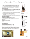
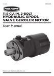
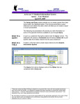
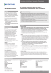
The Ultimate Lock™ 3000 Series Installation Guide Congratulations on purchasing the finest engineered deadbolt lock on the market, The Ultimate Lock™. It is vital that your lock is installed properly to provide the maximum protection possible. Read these instructions completely before you begin the installation. More information can be found at our website: www.TheUltimateLock.com. IMPORTANT: Register your lock’s serial number! Go to www.TheUltimateLock.com and click the “Register Your Lock” link. Before You Start a. This lock is designed for a right- or left-handed door that opens into the home or office with a deadbolt currently installed at a 2-3/8" or 2-3/4" backset (centered from the edge of the door). It can be installed on an outward swinging door, but special instructions are required. See www.TheUltimateLock.com for details. b. To provide maximum protection, The Ultimate Lock™ should be installed in a solid 1-3/4” thick wood door or steel-skinned, insulation or foam filled door mounted in a double studded door frame. c. If your door does not already have a deadbolt installed, it is highly recommended that you purchase an installation jig kit for deadbolts and door handles. These kits include special hole saws, templates, and other aids to simplify the installation process. If your door has a metal skin, be sure your kit includes Bi-Metal hole saws to cut the metal door. A Note About Steel Doors If your door jamb/frame is steel, do not remove the hinge screws! See step 2. Check www.TheUltimateLock.com to get information on installing the striker plate on a steel door frame. Tools You Will Need • No. 1 and No. 2 Phillips Screw drivers or bits • Pencil or steel marking pawl • Electric drill (3/8" chuck) with torque adjustment • Hammer, steel center punch, and 1/2" and 3/4" chisels • Small carpenter’s square (adjustable) • Drill bits: 1/16"(1.5 mm) 3/32" (2.5 mm) 1/8" (3 mm) 9/64" (3.5 mm) 5/32" (4 mm) (supplied in kit) • Pliers (needle nose and regular) • Spade bit or forester bit: 3/4", and 1" • Wood chisel: 1/2" (13 mm) Limited Warranty • Spray lubricant (dry Teflon, Silicon Spray, or similar) • Tape measure or 12-inch ruler • (If no deadbolt installed) Wood or bi-metal hole saw: 2-1/8" and 1" • Small carpenters adjustable square Every Ultimate Lock™ is thoroughly inspected before leaving the factory. It is warranted to be free of defects from workmanship and materials for a period of TEN YEARS from the date of original purchase. Should any trouble develop during the TEN YEAR period, return the complete lock system, freight prepaid, to Ultimate Lock, Inc. at 3776 Greenbriar Dr., Stafford, TX 77477 or call 1-866-MLS-4005 (1-866-657-4005) for one of Ultimate’s Authorized Service Centers nearest you. If our inspection shows the trouble was caused by defective workmanship or material, Ultimate Lock™ will repair (or at our option) replace the lock without charge. Register your Serial Number on line at www.theultimatelocksystems/warranty.com This Warranty does not apply where: • Repairs have been made or attempted by others • Repairs are required because of normal wear and tear • The lock has been abused, misused or improperly installed • Alterations have been made to the lock or its components In no event shall Ultimate Lock™ be liable for any indirect, incidental or consequential damages from the sale or use of the product. This disclaimer applies both during and after the term of the warranty. Ultimate Lock™ disclaims liability for any implied warranties, including implied warranties of “merchantability” and “fitness for a specific purpose”, after the TEN-year term of this warranty. This warranty gives you specific legal rights, and you may also have other rights, which vary from state to state. Some states do not allow the exclusion or the limitation of incidental or consequential damages, so the above limitation or exclusion may not apply to you. Some states do not allow limitation on how long an implied warranty lasts, so the above limitation may not apply to you. *Disclaimer: The Ultimate Lock is only as strong as your door frame. Please contact your local locksmith to visit your home and evaluate your current setup. 1. Identify Your Parts Carefully unpack and check that all parts are in the package. Identify parts and hardware from Figure 1. Record the Serial Number (located inside the lock case) and Date Installed for your lock on the back of this instruction booklet and save this information for future reference. This information will be required if you ever require any warranty. 1 2 3 4 5 6 7 8 9 (qty. 1) (qty. 2) (qty. 6) (qty. 2) (qty. 2) (qty. 2) (qty. 6) (qty. 6) (qty. 2) 1 inch (25 mm) 2 inches (50 mm) 3 inches (75 mm) 4 inches (100 mm) (Not to scale) 6 5 qty. 2 9 qty. 2 qty. 2 Striker Key (qty. 2) 4 qty. 2 Key Lock Locating Ring Deadbolt 3 Bar Support Cushion qty. 6 Bar Platform Lock Bolts 7 qty. 2 Gear 2 8 Housing qty. 2 1 qty. 2 Decorative Cover Door Side Twist Knob Figure 1 Door Frame Side 2. Reinforce Your Hinges a. It is very important to reinforce the hinges of your door to get maximum protection from forced entry. Your Ultimate Lock™ comes with 12 special screws to secure the hinges to the studs of the door frame, and not the door jamb. The six shorter screws go into the middle of the door edge if possible or one inside and one outside hole on a steel-skinned or thin door. b. See Figure 2 and remove half of the existing screws from each of the three hinges as shown in the diagram. If the screws in the door are machine screws (NOT wood screws), do not remove them. Some metal doors have a metal door jamb and use machine screws to hold the hinges to the door. c. Use the special 5" (127 mm) long x 5/32" (4 mm) diameter drill bit provided to drill out the exposed screw holes all the way into the studs behind the door frame. The longer screws go in the frame and the shorter screws go in the door side of the hinge. NOTE: If the door is fiber glass or steel sheeted, do not pre-drill the holes in the door hinges unless the screws have trouble going into the door. If you run into resistance getting the screws into the door, STOP, predrill the screw holes, and screw in the shorter screws until snug. If your drill has adjustable torque, set the torque to slip just as the screw is snug. This is also an excellent time to lightly lubricate the hinge pins one at a time with a suitable lubricant to stop squeaks and rust. Figure 2 Do o Sid r e Do or Fr Sid ame e Install shorter screws into door NOTE: Door frame side only gets screws on the inside two holes closest to center of hinge. Door will either get two screws in center of door or, if no screws are in center of the door, one screw in the top inside hole and one screw in bottom outside hole (typically seen on a steel skinned door). Install longer screws into door jamb 3. Measure and Mark a. For doors with a deadbolt or key lock: Remove the old lock from the door. Measure the distance from the center of the hole for the old lock to the edge of the door. It will be either 2-3/8" or 2-3/4". Also measure the diameter of the hole in the edge of the door for the bolt. It should be 1 inch (25 mm) in diameter. Check that the new deadbolt will slide into the hole. If not, use a 1-inch spade drill and expand the hole to the proper size. You can now skip to step 4. b. For doors without an existing deadbolt: See Figure 3 and measure the backset for your door handle/knob. The center of the knob will either be 2-3/8” or 2-3/4” from the edge of the door. Also measure the thickness of your door. Write these measurements down. c. Your Ultimate Lock™ should be installed 5-1/2 to 6” (140 to 153 mm) ABOVE the center of the door handle/ knob, and the backset should match the door handle/ knob. Measure this distance above the center of the existing door handle/knob and draw a horizontal line from the door edge back approximately 3 inches on both sides of the door and across the edge of the door (see Figure 3). Hole must be 1” in diameter. Drill out if needed. Ba c Me kset as ure me nt 5½ Figure 3 s he to nc 6i 4. A Note About Steel Doors For steel doors with steel door jambs: When installing the Ultimate Lock™ in steel doors or wood doors installed in steel door frames that have not yet had a deadbolt installed in them but have a deadbolt latch hole already in the door frame, the lock must be installed in line with the hole in the steel door jamb for the deadbolt striker (usually covered with a plate). DO OR R MB F D C C C 2 3/4” F (70 MM) A E B 2 " -(51) G FOLD HERE DRILL GUIDES 1 12 " -(38) PART # 30° 1 34 " -(44) C D 2 C C (60 MM) 2 3/8” Place the paper drilling template (or install jig) on the centerline of the recess, and draw a line on the door (Figure 4). This will be the centerline for installing the lock in the door. Figure 4 5. Measure and Mark Holes F E C L E ID 13 4" -(44) 11 2" -(38) FOLD HERE 2 U G F D C C PART # C S G IL R D ° 0 3 2 " -(51) 2 3/8” (60 MM) A D B 2 3/4” (70 MM) C C Refer to the backset measurement recorded in step 3b, and determine the appropriate lock center (A or B) on the paper template or set the drilling jig to the proper backset. Fold and place the template on the INTERIOR of the door as shown in Figure 5, and mark the location of pilot hole A or B. Refer to the door thickness as measured in step 3b and mark the deadbolt center hole (G) that matches your door thickness. Place paper template on interior side of door 6. Prepare Your Door JA E O DO E Ba c Me kset as ure me nt Figure 5 These steps are not necessary if you are replacing an existing deadbolt lock. The hole for the cylinder lock and deadbolt will already be in place. a. Using the 5" long 5/32" bit provided, drill the pilot hole for the lock cylinder as marked in Step 5 (template mark A or B) to match the backset of the handle/knob). Make sure the drill bit goes straight through the door. b. Using the same bit, drill the pilot hole for the deadbolt. Make sure the drill bit goes in level, perpendicular and the pilot hole is in the middle of the door. c. Using a 2 1/8" hole saw, drill out the hole for the lock cylinder. To prevent splintering the surface of the door, do not drill completely through the door from one side, drill through from both side of the door. Push nail through pilot hole to mark location for center of striker hole. d. Close the door and push a 2 to 2¼" long nail through the deadbolt pilot hole, from inside the cylinder lock hole, to mark the location for the striker plate hole (Figure 6). e. Using a 1" hole saw, spade bit, or forester bit, drill the hole for the deadbolt (Figure 3). Insert deadbolt and mark its outline. Use a sharp chisel to mortise the new deadbolt faceplate 1/8" (3 mm) deep into the edge of the door. Figure 6 7. Install Deadbolt a. Look at your door from the inside of the house or room and note if the hinges are on the right or left side of the door. b. For a door with hinges on the right, install deadbolt with the cross hole at the bottom. For a door with hinges on the left, install the deadbolt with the cross hole on top (Figure 7). c. Mark and drill two 3/32" (2 mm) pilot holes for the two faceplate screws , insert the deadbolt properly and install the screws. The deadbolt face plate should be flush with the edge of door not sticking out from the surface of the edge of the door. Looking at door from inside: Cross hole at bottom for hinges on right Cross hole at top for hinges on left Figure 7 8. Install Key Lock a. Hold new key lock in your left hand, and rotate the flat blade to a horizontal position. b. With the deadbolt RETRACTED, position the key lock on the outside of the door with the locating ring fitted to the back of the key lock, while inserting the flat blade (tailpiece) horizontally through the deadbolt crosshole (Figure 8) . NOTE: The deadbolt crosshole will be either at the top or bottom of the unit, as determined in steps 7a and 7b above. Make sure the tailpiece is flat (or horizontal) when inserted through the crosshole. c. Install the two long lock bolts through the platform and screw them into the key lock. Snug up the lock bolts, but do not fully tighten them at this point. Make sure the tailpiece does not stick out of the platform, with the black plastic surface, more than 1/8". If it does, remove the lock and use two pairs of pliers to break off the first segment of the tail piece. NOTE: Be very careful not to bend the rest of the tailpiece! Now replace the lock assembly into the door as before and snug up the lock bolts but do not tighten yet. Using the adjustable square make sure the Platform is square to the edge of the door and the tail piece is in the center of the large hole in the Platform. With this done, using a #2 Phillips hand screw driver (NOT a power drill), alternately tighten each lock screw until they are nice and tight but not over tightened as this can cause the housing to bend in the middle causing the gear hole to collapse where the gear will not turn properly. Instructions on how to fix the gear if this happens are on the web site www.TheUltimateLock.com. d. Insert the key into the lock and check for correct operation. You should be able to remove the key at both the locked and unlocked positions. If the lock does not function properly, the flat blade (tailpiece) is most likely not positioned correctly. e. P osition the housing over the platform with the round corners on the front of both pieces matching up on a 2-3/8" back set and the square corners on the back of both pieces matching up on a 2-3/4" backset. This will expose six holes, three top and three bottom. Mark these holes with a pencil or metal pawl. Remove the housing and using the 9/64" drill bit, predrill the holes to a maximum depth of 1-1/4". Clean away all drilling dust. Drilling deeper than 1-1/4" may penetrate the outside surface of the door. Use masking tape or a mark on the drill bit to indicate 1-1/4". Deadbolt Make sure deadbolt is oriented properly (See step 7) 9 Key Lock Lock Bolts Locating Ring Keylock flat blade/tailpiece must be horizontal when inserted through deadbolt. Housing Figure 8 9. Install Security Bar d. The gear should slide in smoothly. Using the key in the key lock, see if the gear turns smoothly. If you cannot turn the gear smoothly go to www.TheUltimateLock.com for correction instructions. PATENT PENDING c. Align the arrow on the first tooth of the gear with the marking corresponding to the backset measurement previously recorded and engage the gear teeth (Figure 9), making sure that flat tailpiece of key lock properly mates with gear cross hole. 238 b. Position security bar in place and start gear into hole. Install gear with alignment mark matching the backset measurement 234 a. Apply a dry, multipurpose lubricant to moving parts (teeth of gear, and security bar). (Hinges to the RIGHT) PATENT PENDING 234 238 (Hinges to the LEFT) Figure 9 10. Final Lock Assembly a. Install the housing over the platform and security bar assembly, making sure to align the corners so the six predrilled holes lineup with the holes in the housing. Using the six round head screws , attach the housing to the door and the platform assembly. b. Position the bar support cushion at the edge of the door in the open area of the lock assembly against the tips of the housing assembly (Figure 10). If there is any up and down movement, move the bar support cushion down. The small front edge of the bar support cushion should be even with the edge of a wood door or the wood core of a steel skinned door. Using the 9/64" drill bit, mark the position of the two holes in the bar support cushion on the door. DO NOT DRILL HOLES. Remove the bar support cushion and using the 3/32" drill bit, pre drill the two holes. Using screws found in the small screw package, mount the bar support cushion to the edge of the door. Using the twist knob and the key, check the lock for smooth operation and make sure the security bar clears the bar support cushion. If there is a problem, see the troubleshooting instructions on the web site, www.theultimatelock.com. If the lock works smoothly you are ready to install the decorative cover. c. Insert the point of a No. 1 screwdriver into the two mounting holes for the two decorative cover case screws . Make sure the holes are clear of debris from die cast flash. d. Install decorative cover and secure with two case screws using No. 1 Phillips screwdriver. Alternately tighten each screw until both are tight. DO NOT OVERTIGHTEN! e. Use the twist knob and key to exercise the lock. Make sure the lock still turns smoothly. If the lock hangs or seems to be obstructed while turning, see the troubleshooting instructions on the web site, www.theultimatelock.com. f. With security bar retracted, position twist knob in place (oriented vertically), and secure with screw . Bar Support 4 Figure 10 3 Platform Housing 2 Decorative Cover 1 Twist Knob Figure 11 11. Install Striker Plate a. Remove the old deadbolt striker plate from the door frame. Close the door and see if the new deadbolt aligns with the old hole in door jamb. If not, use the 1" spade bit to enlarge the old hole for the new bolt. Make sure it will extend the full 1” depth and the security button will engage. b. With the deadbolt partially extended, close the door until the deadbolt touches the door frame. Mark the top and bottom of the deadbolt on the edge of the frame. c. Hold the striker plate on the door frame with the two edge tabs on the edge of the door frame aligned to the top and bottom of the deadbolt. Holding the striker plate in place, mark the outside edge of the striker plate. This will usually be larger than the old striker plate. Using the chisel, mortise out the frame to fit the Ultimate Lock striker plate. Fit the striker plate in upside down to check fit of mortise. Correct as needed until flush. Mark locations for holes for power screws Figure 12 Mark for countersink holes d. Holding the striker plate in position, mark the position of two 1/8 inch recessed holes in the striker plate (Figure 12) in the mortise of 30° the door frame. Using the 3/4" drill bit, start a hole 1/8" in front 3/8 inch of the hole marks and a 3/8" deep hole at a 30 degree angle (Figure 13). Position the striker plate to make sure it fits flush in the mortise. Hold the striker plate in position, close the door and View from top of door jamb activate the lock to verify both deadbolts clear the striker plate when thrown. Correct as necessary and then using the 3/32" drill bit, predrill the two small positioning holes in the striker plate. Figure 13 Using the 2 small flat head wood screws in the small screw package, attach the striker plate. Close door and verify that the deadbolts clear the striker plate. Using the 5"5/32" drill bit provided, predrill the holes for the 3-1/2" mounting screws at a 30 degree angle, to a depth of the full length of the drill bit. Set the torque on your power drill and using a #2 bit slowly screw the 3-1/2” screws into the door frame, applying firm pressure on the bit. Close the door and recheck the functioning of the lock. TIP: Do not force the screws in. If the screws get too tight before they are all the way in, either apply soap to screw threads, or carefully remove the screw and re-drill the pilot hole and try again. For steel door frames: If the door jamb is steel you will have to surface-mount the striker plate and drill 2-5/8" holes in the steel frame at the point of the mounting holes in the striker plate to accommodate the dimples in the striker plate. If there is no wood behind the steel frame, you will have to use 1/4" x 1" flat-head machine screws with washers and nuts to mount the striker plate. You will need two 1/4" x 1" flat head machine screws, two 5/16" flat washers, two 1/4" flat washers, two 1/4" lock washers, and two 1/4" nuts. Holding the 1/4" screw in the hole, take a pair of curved, long nose pliers and place the 5/16" washer on the screw, then the 1/4" flat washer, then the 1/4" lock washer, then the 1/4" nut and tighten them down snug. 12. Finishing Up You now have the protection of the Ultimate Lock! For added safety, it is recommended that you apply the “Protected by Ultimate Lock System” decal to the door or a nearby window. “BE SAFE, LOCK UP, AND SET THE INSIDE SAFETY BUTTON WHEN YOU RETIRE” Operation The Ultimate Lock™ utilizes two deadbolts that work in unison—a mortise deadbolt and a rim deadbolt. The secondary rim deadbolt protrudes slightly across the door frame and makes it very easy to verify that your door is locked. To lock your door, simply turn the twist knob counterclockwise 90° until it is horizontal. To unlock the door, turn the twist knob clockwise 90° until it is vertical. For even more security, The Ultimate Lock™ features a patented lockout feature that will prevent ANY key from opening the door. To engage the lockout pin, simply press the button in the locked position until it latches in place. You are now ultimately protected from intrusion! Non-standard Installations Installing The Ultimate Lock™ in non-standard configurations requires special instructions. For guidance on installing the lock on french doors, on outward-opening doors, or in safe rooms, please visit our website (www.TheUltimateLock.com). For Your Records It is recommended that you record the details of your Ultimate Lock™ for future reference. This information will be required if you ever request warranty service. Date Purchased: ______________________________________________________________ Purchased From: ______________________________________________________________ Serial Number: _______________________________________________________________ Millennium Lock, Inc 3776 Greenbriar Dr. Stafford, Texas 77477 Telephone: (713) 266-1400 Fax: (713) 975-9714