1
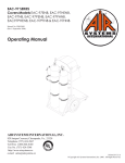
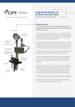
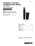
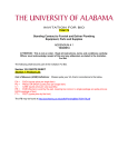
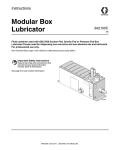
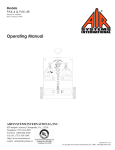
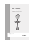
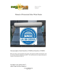
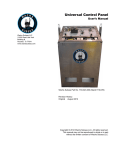
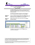
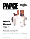
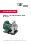
Instruction & Operation Manual 650150000094418_A EN SAFEGUARD™ Lubrication System Console Proven Solution for the Global Compression Industry™ Contents 1. CPI SAFEGUARD™ Lubrication System Console ............................................................................... 5 2. Safety & Warnings .................................................................................................................................. 6 2.1 Qualified People .................................................................................................................................. 6 2.2 Hazardous Location Approval ............................................................................................................. 6 2.3 Warnings ............................................................................................................................................. 7 3. Repair and Maintenance ....................................................................................................................... 10 4. SAFEGUARD™ Lubrication System Overview .................................................................................. 11 4.1 Single Motor Package Lubrication System P&ID Drawing ............................................................... 11 4.2 Dual Motor Package Lubrication System P&ID Drawing .................................................................. 12 4.3 Lubrication System Console Overview ............................................................................................. 13 5. SAFEGUARD™ Lubrication System Configurations ........................................................................ 16 5.1 Single Motor & HVLP Gear Box Configuration ................................................................................. 16 5.2 Dual Motor & HVLP Gear Box Configuration .................................................................................... 17 6. Lubrication System Components ........................................................................................................ 18 6.1 Tank .................................................................................................................................................. 18 6.2 Bottom Plane ..................................................................................................................................... 18 6.2.1 Single Motor Package ................................................................................................................ 18 6.2.2 Dual Motor Package ................................................................................................................... 18 6.3 Motor Package .................................................................................................................................. 18 6.3.1 Motor .......................................................................................................................................... 18 6.3.2 Coupling ..................................................................................................................................... 18 6.3.3 HVLP Gear Box .......................................................................................................................... 19 6.3.4 HVLP Pump ............................................................................................................................... 19 6.3.5 Coupling Guard .......................................................................................................................... 19 6.4 Divider Blocks ................................................................................................................................... 19 6.4.1 XD Divider Blocks ...................................................................................................................... 19 6.4.2 HP Divider Blocks ...................................................................................................................... 19 6.5 Lubrication No-Flow Monitoring Devices .......................................................................................... 20 6.5.1 CPI Captured Proximity Switch .................................................................................................. 20 6.5.2 CPI Proflo Jr. .............................................................................................................................. 20 6.5.3 CPI Proflo PF1 ........................................................................................................................... 20 6.5.4 Whitlock DNFT Proximity Switch ............................................................................................... 20 6.5.5 Whitlock DNFT LED ................................................................................................................... 21 6.5.6 Whitlock DNFT LED-PS ............................................................................................................. 21 6.5.7 Whitlock DNFT LCC ................................................................................................................... 21 650150000094418_A 2 6.5.8 Whitlock DNFT PRG .................................................................................................................. 21 6.5.9 Whitlock DNFT PRG-PS ............................................................................................................ 21 6.6 Junction Box ...................................................................................................................................... 22 6.7 Heater................................................................................................................................................ 22 6.8 Level Switch ...................................................................................................................................... 22 6.9 Lubrication Hydraulic Circuit ............................................................................................................. 23 6.9.1 Hydraulic Circuit Schematic ....................................................................................................... 24 6.9.2 Low Pressure Valve ................................................................................................................... 24 6.9.3 T-Strainer (100 Mesh) ................................................................................................................ 24 6.9.4 Primer Bowl ................................................................................................................................ 24 6.9.5 High Pressure Valve .................................................................................................................. 24 6.9.6 High Pressure Filter (10 micron) ................................................................................................ 25 6.9.7 Manual Pump ............................................................................................................................. 25 6.9.8 Gauges ....................................................................................................................................... 25 6.9.9 POPR™...................................................................................................................................... 25 7. Installation of the CPI SAFEGUARD™ Lubrication System Console .............................................. 26 7.1 Mounting Single Motor Package Lubrication System ....................................................................... 26 7.2 Mounting Dual Motor Package Lubrication System .......................................................................... 27 7.3 Machinery Directive ........................................................................................................................... 28 7.4 Electrical Termination of the Electrical Motor ................................................................................... 28 7.5 Electrical Termination of the Electrical Heater .................................................................................. 28 7.6 Electrical Termination of the Level Switch Controller ....................................................................... 28 7.7 Termination of the Hazardous Location Junction Box ...................................................................... 29 7.8 Grounding of the Lubrication System ................................................................................................ 29 7.9 Installation References...................................................................................................................... 29 8. Operating the SAFEGUARD™ Lubrication System Console ........................................................... 30 8.1 Filling and Priming the System ......................................................................................................... 30 8.2 Filling and Priming of the Divider Block and Lubrication Lines ......................................................... 32 8.3 Pre-Lubrication of the System ........................................................................................................... 32 8.4 Setting the Correct Lubrication Cycle Time (Machinery Operating) ................................................. 34 8.4.1 Adjusting HVLP Pumps .............................................................................................................. 34 8.4.2 Break-In vs. Normal Operating Lube Rate ................................................................................. 35 9. Maintenance of the Lubrication System ............................................................................................. 36 9.1 Cleaning or Replacing Lubrication System Filters ............................................................................ 36 9.2 Cleaning or Replacing a Low Pressure T-Strainer ........................................................................... 36 9.3 Replacing a High Pressure Filter ...................................................................................................... 37 650150000094418_A 3 9.4 Replacing a High Pressure filter while out of service ........................................................................ 37 10. Maintenance ........................................................................................................................................ 39 11. Troubleshooting .................................................................................................................................. 40 11.1 HVLP Lubricator & HVLP Pump ..................................................................................................... 40 11.2 Divider Blocks ................................................................................................................................. 42 12. Shipping & Handling ........................................................................................................................... 45 13. Specifications ...................................................................................................................................... 46 650150000094418_A 4 1. CPI SAFEGUARD™ Lubrication System Console The CPI SAFEGUARD™ Lubrication System Console has been designed as a standalone lubrication console for all types of industrial machinery including Reciprocating Compressors and Reciprocating Pumps. The CPI Lubrication System Console is designed to work with CPI’s extensive line of divider blocks and lubrication system accessories to provide precise lubrication to your machinery. Using one of CPI’s patented shutdown devices or proximity switches, precise timed and monitored lubrication is provided to your equipment eliminating the significant costs of over or under lubrication. The SAFEGUARD™ Lubrication System Console is fitted as standard with a 30-Gallon (useable) reservoir, T-Type Oil strainer, Primer Bowl, Motor Driven 2-Pump HVLP Gear Box with Suction Manifold, Discharge Manifold, Pressure Gauge, POPR (Pop Open Pressure Relief), Purge Port Check Valve and 10-Micron Discharge Side Filter. The 2-Pump HVLP Gear Box is direct coupled to the electric motor via a flexible shaft coupling which is covered by a coupling guard. There is the option of adding a second motor and HVLP Gear Box. Fig. 1- Showing CPI SAFEGUARD™ Lubrication System Console Front View 650150000094418_A 5 2. Safety & Warnings 2.1 Qualified People The product / system described in this documentation may only be operated by personnel qualified for the specific task in accordance with the relevant documentation, in particular its warning notices and safety instructions. Qualified personnel are those who based on their training and experience, are capable of identifying risks and avoiding potential hazards when working with these product / systems. 2.2 Hazardous Location Approval This SAFEGUARD™ Lubrication System Console has been Designed, Manufactured and Integrated in accordance with all European Directives; ATEX Directive 94/9/EC, PED 97/23/EC, EMC 2004/08/EC, Machinery Directive 2006/42/EC The SAFEGUARD™ Lubrication System Console is marked as below; Fig. 2 – Showing Label for CPI SAFEGUARD™ Lubrication System Console . 650150000094418_A 6 2.3 Warnings The following warnings are for the setup, use, grounding, maintenance, and repair of this equipment. The exclamation point symbol alerts you to a general warning and the hazard symbols refer to proceduresspecific risks. When these symbols appear in the body of this manual, refer back to these Warnings. Product-specific hazard symbols and warnings not covered in this section may appear throughout the body of this manual where applicable. Warning SKIN INJECTION HAZARD High-pressure fluid from dispensing device, hose leaks, or ruptured components will pierce skin. This may look like just a cut, but it is a serious injury that can result in amputation. Get immediate surgical treatment. Do not point dispensing device at anyone or at any part of the body. Do not put your hand over the fluid outlet. Do not stop or deflect leaks with your hands, body, glove, or rag. Follow the Pressure Relief Procedure when you stop dispensing and before cleaning, checking, or servicing equipment. Tighten all fluid connections before operating the equipment. Check hoses and coupling daily. Replace worn or damaged parts immediately. FIRE AND EXPLOSION HAZARD When flammable fluids are present in the work area, such as gasoline and windshield wiper fluid, be aware that flammable fumes can ignite or explode. To help prevent fire and explosion: Use equipment only in well-ventilated area. Eliminate all ignition sources, such as cigarettes and portable electric lamps. Keep work area free of debris, including rags and spilled or open containers of solvent and gasoline. Do not plug or unplug power cord or turn lights on or off when flammable fumes are present. Ground all equipment in the work area. Use only grounded hoses. Stop operation immediately if static sparking occurs or you feel a shock. Do not use equipment until you identify and correct the problem. Keep a working fire extinguisher in the work area. 650150000094418_A 7 Warning EQUIPMENT MISUSE HAZARD Mechanical machines contain rotating parts. Fatal or sever injuries and substantial material damage can occur if the required covers are removed or if machines are not handled, operated or maintained properly. Do not remove Guards while equipment is energized. Only remove Guards when it is safe to do so. Only operate equipment when Guards are fixed in place with appropriate Socket Head Cap Screws supplied with this equipment. Do not exceed the maximum working pressure or temperature rating of the lowest rated system component. See Technical Data in all equipment manuals. Use fluids and solvents that are compatible with equipment wetted parts. See Technical Data in all equipment manuals. Read fluid and solvent manufacturer’s warnings. For complete information about your material, request MSDS from distributor or retailer. Turn off all equipment and follow the Pressure Relief Procedures when equipment is not in use. Check equipment daily. Repair or replace worn or damaged parts immediately with genuine manufacturer’s replacement parts only. Do not alter or modify equipment. Alterations or modifications may void agency approvals and create safety hazards. Make sure all equipment is rated and approved for the environment in which you are using it. Use equipment only for its intended purpose. Call CPI for information. Route hose and cables away from traffic areas, sharp edges, moving parts, and hot surfaces. Do not kink or over bend hoses or use hoses to pull equipment. Comply with all applicable safety regulations. PERSONAL PROTECTIVE EQUIPMENT Wear appropriate protective equipment when in the work area to help prevent serious injury, including eye injury, hearing loss, inhalation of toxic fumes, and burns. This protective equipment includes but is not limited to: Protective eye wear, and hearing protection. Respirators, protective clothing, and gloves as recommended by the fluid and solvent manufacturer. 650150000094418_A 8 Warning High Voltage Electrical machines contain live parts. Fatal or sever injuries and substantial material damage can occur if the required covers are removed or if machines are not handled, operated or maintained properly. Only remove covers in compliance with the applicable regulations Operate the machine properly Perform regular maintenance on the machine Risk of Burning Electrical machines have hot surfaces. Fatal or sever injuries and substantial material damage can occur if the required covers are removed or if machines are not handled, operated or maintained properly. Allow the machine to cool down before starting any work on it Special Instructions – Explosion Proof Equipment The increased level of danger in hazardous areas demands that you pay particular attention to the notes marked. 650150000094418_A Ensure the lubrication system console and its individual components both electrical and mechanical have a sufficient level of protection for the intended area of use. 9 3. Repair and Maintenance For guidance on repair, servicing or replacement contact: United Kingdom Unit 5, Smitham Bridge Road Hungerford, Berkshire RG17 0QP, UK Tel: +44 (0)1488 684 585 Fax: +44 (0)1488 684 001 II 2 G 94/9/EC ATEX Directive 2006/42/EC Machinery Directive 97/23/EC Pressure Directive 2004/108/EC Electromagnetic Compatibility Directive 2011/65/EU Restriction of Hazardous Substances Directive France 5 Rues des PlatanesF-59570 Bavay, France Tel: +33 (0)327 63 16 64 Fax: +33 (0)327 63 08 77 Germany Robert-Bosch-Street 3-D-64572 Buttelborn, Germany Tel: +49(0) 6152 / 93160 Fax: +49 (0) 6152 / 82640 Holland Harregatplein 17 3214 VP Zuidland, Netherlands Tel: +31 (0)1816 63149 Fax: +31 (0)1816 64117 United States Compressor Products International 4410 Greenbriar Drive Stafford Texas, 77477 USA Tel: +1 281 207 4600 Fax: +1 281 207 4612 650150000094418_A 10 4. SAFEGUARD™ Lubrication System Overview 4.1 Single Motor Package Lubrication System P&ID Drawing Fig. 3 - Showing P&ID Drawing for the Single Motor Package Lubrication System Console IMPORTANT: Please refer to the specific P&ID drawing that is supplied with your equipment. 650150000094418_A 11 4.2 Dual Motor Package Lubrication System P&ID Drawing Fig. 4 - Showing P&ID Drawing for the Dual Motor Package Lubrication System Console IMPORTANT: Please refer to the specific P&ID drawing that is supplied with your equipment. 650150000094418_A 12 4.3 Lubrication System Console Overview This section describes the specifications for the major components of the lubrication system. Fig. 5 - Showing lubrication oil supply tank specification for Lubrication System Console 650150000094418_A 13 Fig. 6 - Showing motor package specification for Lubrication System Console IMPORTANT: The Electrical Heater and Electrical Motor are required to be wired to a Start, Stop and Emergency Stop. Fig. 7 - Showing oil distribution & no-flow monitor specification for Lubrication System Console 650150000094418_A 14 Fig 8 – Showing Supply & Discharge hydraulic circuits for the Lubrication System Console 650150000094418_A 15 5. SAFEGUARD™ Lubrication System Configurations The CPI SAFEGUARD™ Lubrication System Console is available in two basic configurations. 5.1 Single Motor & HVLP Gear Box Configuration The single configuration consists of the following: Panel sub-assembly, single motor package o Panel frame assembly, single motor package o Reservoir assembly, stainless steel, 30 gallon o Single oil supply circuit, duplex t-strainers o Manual priming pump circuit o One (1) or two (2) oil discharge circuit, duplex filters Overpressure return circuit, single discharge circuit One (1) or two (2) divider block assembly, mounting plate, No-Flow Device, Gauge, NEOMAG Motor package assembly, HVLP, two (2) pumps, 90L frame XPFC motor Fig. 9 – Showing Single Motor and HVLP configuration 650150000094418_A 16 5.2 Dual Motor & HVLP Gear Box Configuration The dual motor and HVLP Gear Box configuration can be used to provide redundancy for specific applications or to provide lubrication to multiple compressors from independent drives. The dual configuration consists of the following: Panel sub-assembly, dual motor package o Panel frame assembly, dual motor package o Reservoir assembly, stainless steel, 30 gallon o Oil supply circuit, duplex filters o Manual priming pump circuit o One (1) or two (2) oil discharge circuits, duplex t-strainers Overpressure return circuit One (1) or two (2) divider block assembly, mounting plate, No-Flow device, gauge, NEOMAG Two motor package assembly, HVLP, two (2) pumps, 90L frame XPFC motor Fig. 10 – Showing Dual Motor and HVLP motor package configuration 650150000094418_A 17 6. Lubrication System Components 6.1 Tank A quality reservoir with level gauge, filler breather, and temperature gauge, made from seven (7) gauge stainless steel with a capacity of 50 gallons (189 liters), with 30 usable gallons (114 liters) between level switches. The tank provides a positive feed of oil to pumps, with options of a heater, low level, and high level switch. 6.2 Bottom Plane 6.2.1 Single Motor Package A pan mounted package with a HVLP gear box and two (2) HVLP pumps directly driven by a single electric motor. Protection from rotating parts is provided by a non-sparking aluminum fixed Guard. 6.2.2 Dual Motor Package A pan mounted package with two (2) HVLP gear boxes and four (4) HVLP pumps directly driven by two (2) electric motors. Protection from rotating parts is provided by a non-sparking aluminum fixed Guard. 6.3 Motor Package 6.3.1 Motor The lubrication system console is designed to house a 90L frame motor. The electrical motor has the following Hazardous Location Approvals; Ex II 2 G Ex de IIC T1 – T4 Gb See appendix for the motor specification 6.3.2 Coupling The coupling is the interface between the Motor and the HVLP Gear Box. The coupling has the following Hazardous Location Approvals; Ex II 2 GD c T4 See appendix for the coupling specification 650150000094418_A 18 6.3.3 HVLP Gear Box The HVLP Gear Box has the following Hazardous Location Approvals; Ex II 2 G c T4 See appendix for HVLP Gearbox User Instructions 6.3.4 HVLP Pump The HVLP Pump has the following Hazardous Location Approvals; Ex II 2 G c T4 See appendix for HVLP Pump User Instructions 6.3.5 Coupling Guard The fixed coupling Guard is made from non-sparking aluminum which is there to prevent injury from rotating parts. WARNING: Do not remove Guards while equipment is energized. Only remove Guards when it is safe to do so. Only operate equipment when Guards are fixed in place with appropriate Socket Head Cap Screws supplied with this equipment. 6.4 Divider Blocks 6.4.1 XD Divider Blocks The XD Divider Block has the following Hazardous Location Approvals Ex II 2 G c T6 See appendix for XD Divider Block User Instructions 6.4.2 HP Divider Blocks The HP Divider Block has the following Hazardous Location Approvals Ex II 2 G c T6. See appendix for HP Divider Block User Instructions 650150000094418_A 19 6.5 Lubrication No-Flow Monitoring Devices 6.5.1 CPI Captured Proximity Switch The Captured Proximity Switch has the following Hazardous Location Approvals; Ex II 3 G Eex nC II T6 (Ta = -20°C to 40°C) CLASS I DIVISION 1 GROUPS A, B, C, and D; Temperature Code T5 CLASS I ZONE 1 AEx md IIC See appendix for User Instructions 6.5.2 CPI Proflo Jr. The Proflo Jr. has the following Hazardous Location Approvals; Ex II 3 G Eex nAn nC II T4 (Ta = -20°C to 40°C CLASS I DIVISION 1 GROUPS A, B, C, and D; Temperature Code T4 CLASS I ZONE 1 AEx md IIC See appendix for User Instructions 6.5.3 CPI Proflo PF1 The Proflo Jr. has the following Hazardous Location Approvals; CLASS I, DIVISION 2, GROUPS A, B, C, and D; Temperature Code T4A See appendix for User Instructions 6.5.4 Whitlock DNFT Proximity Switch The Whitlock DNFT Proximity Switch has the following Hazardous Location Approvals Ex II 2 G Eex md IIC T5 See appendix for User Instructions 650150000094418_A 20 6.5.5 Whitlock DNFT LED The Whitlock DNFT LED has the following Hazardous Location Approvals Ex II 2 G Eex md IIC T5 See appendix for User Instructions 6.5.6 Whitlock DNFT LED-PS The Whitlock DNFT LED-PS has the following Hazardous Location Approvals Ex II 2 G Eex md IIC T5 See appendix for User Instructions 6.5.7 Whitlock DNFT LCC The Whitlock DNFT LCC has the following Hazardous Location Approvals Ex II 2 G Eex md IIC T5 See appendix for User Instructions 6.5.8 Whitlock DNFT PRG The Whitlock DNFT PRG has the following Hazardous Location Approvals Ex II 2 G Eex md IIC T5 See appendix for User Instructions 6.5.9 Whitlock DNFT PRG-PS The Whitlock DNFT PRG-PS has the following Hazardous Location Approvals Ex II 2 G Eex md IIC T5 See appendix for User Instructions 650150000094418_A 21 6.6 Junction Box In the case when Lubrication No-Flow Monitoring Devices are selected that do not meet the intended Zone 1 requirements, they are required to be installed in a suitable Explosion Proof Junction box. The Adalet XJHAGCHX N4 has the following Hazardous Location Approvals Ex II 2 G Eex md IIC T5 WARNING: To prevent ignition of explosive atmospheres, disconnect from supply circuits before opening enclosure. Keep tightly closed when circuits are alive. 6.7 Heater The electrical heater has the following Hazardous Location Approvals Ex II 2 GD Ex d IIC T4 Gb Ex tb IIC T135°C Db See appendix for User Instructions 6.8 Level Switch The lubrication system console can be fitter with either one (1) or two (2) level switches. The Level Switch has the following Hazardous Location Approvals Ex II 1GD Eex ia IIC T5 See appendix for User Instructions 650150000094418_A 22 6.9 Lubrication Hydraulic Circuit The CPI SAFEGUARD™ Lubrication System Console has a supply and discharge circuit that has two separate feed lines. The CPI SAFEGUARD™ Lubrication System Console has the ability for one line to be worked on (maintained) while the other is operational. Depending on the application there is the option of having one (1) or two (2) discharge circuits and the option of having one (1) or two motor packages each with two pumps. Supply Circuit Discharge Circuit Fig. 11 – Showing Supply and Discharge Circuit for CPI Lubrication System Console 650150000094418_A 23 6.9.1 Hydraulic Circuit Schematic Fig.12 illustrates the supply and discharge circuits in schematic form. Reference the schematic diagram while operating the equipment. Please refer to Section 8. Maintenance of the Lubrication if any component requires attention. Oil Supply LP Valve Filter Primer LP Valve PLP Pump LP Valve Tank LP Valve Filter Primer Manual Pump HP Valve LP Valve Discharge Manifold Gauge and POPR HP Valve Filter Bleed Valve HP Valve HP Valve Filter Bleed Valve HP Valve Divider Block Fig. 12 – Showing Supply and Discharge circuit schematic 6.9.2 Low Pressure Valve The low pressure valves in the supply circuit are used to isolate the low pressure filter during scheduled maintenance. The low pressure valves have lockout capability. 6.9.3 T-Strainer (100 Mesh) The t-strainer on the supply reduces coarser contaminants that may accumulate in the tank from entering the lubrication system. 6.9.4 Primer Bowl The Primer bowl allows air in the hydraulic circuit to be removed and maintains oil supply at the pump inlet. 6.9.5 High Pressure Valve The high pressure valves in the discharge circuit are used to isolate the high pressure filter during scheduled maintenance. 650150000094418_A 24 6.9.6 High Pressure Filter (10 micron) The filter on the discharge circuit reduces fine contaminants from entering the divider blocks system. 6.9.7 Manual Pump The manual pump is used for priming of the lubrication system. Refer to section 8.2 Filling and Priming the Lubrication System. 6.9.8 Gauges The gauges are used to indicate the overall health of the lubrication system, by displaying the pressure at specific points in the lubrication system. If an over pressure condition occurs please refer to section 11. Troubleshooting. 6.9.9 POPR™ The Pop Open Pressure Relief (POPR™) is available in two pressure ratings; 3500psi (238 bar) and 5500psi (374 bar). If the pressure in the hydraulic discharge circuit exceeds the POPR™ rating the POPR™ opens and diverts the lubrication oil back to the oil tank or another container for disposal. For operational pressures above 5500psi (374 bar) other pressure relief valves are available. Please contact CPI for specific details. Per Paragraph 2 of Annex 2 of the Pressure Directive the POPR™ device is classified in the same category as the equipment that it protects. See appendix for User Instructions 650150000094418_A 25 7. Installation of the CPI SAFEGUARD™ Lubrication System Console The SAFEGUARD™ Lubrication System Console and its components have been integrated to meet the requirements of a Zone 1 Gas Hazardous Location. Please refer to the label drawing in Section 2.2 Hazardous Location Approvals for specific details. 7.1 Mounting Single Motor Package Lubrication System The CPI SAFEGUARD™ Lubrication System must be bolted down to a flat strong structure such as the machine skid, platform or grating in close proximity to the machine. Four (4) 0.625” (15.875mm) holes are provided on the console base for mounting. Fig. 13 - Showing mounting bolt location for the CPI Lubrication System Console 650150000094418_A 26 7.2 Mounting Dual Motor Package Lubrication System The CPI SAFEGUARD™ Lubrication System must be bolted down to a strong flat structure such as the machine skid, platform or grating in close proximity to the machine. Four (4) 0.625” (15.875mm) holes are provided on the console base for mounting. Fig. 14 - Showing mounting bolt location for the CPI SAFEGUARD™ Lubrication System Console 650150000094418_A 27 7.3 Machinery Directive IMPORTANT: To meet the requirements of the Machinery Directive the following electrical devices are required to be wired to a Control Panel that has integrated Start, Stop and Emergency Stop functions. 1. Electrical Motor 2. Electrical Heater 3. Level Switch Controllers (As applicable) 7.4 Electrical Termination of the Electrical Motor This SAFEGUARD™ Lubrication System Console is supplied with an Electrical Motor with construction to meet the requirements of a Zone 1 Hazardous Location per the ATEX Directive 94/9/EC. Special Attention to the following is required; 1. Type of conductors to connect the electrical motor must be suitable for the voltage and current requirements. 2. The cable glands must have EC-Type certification and be certified for the respective hazardous location area classification. Please refer to the Electrical Motor User Manual accompanying this User Manual for complete guidance on Electrical Connection, commissioning, Operation and Maintenance. 7.5 Electrical Termination of the Electrical Heater This SAFEGUARD™ Lubrication System Console is supplied with an Electrical Heater with construction to meet the requirements of a Zone 1 Gas Hazardous Location per the ATEX Directive 94/9/EC. Please refer to the Electrical Heater User Manual accompanying this User Manual for complete guidance on Electrical Connection, Commissioning, Operation and Maintenance. 7.6 Electrical Termination of the Level Switch Controller This SAFEGUARD™ Lubrication System Console is supplied with a maximum of two (2) level switch controllers with construction to meet the requirements of a Zone 1 Hazardous Location per the ATEX Directive 94/9/EC. Please refer to the Electrical Heater User Manual accompanying this User Manual for complete guidance on Electrical Connection, Commissioning, Operation and Maintenance. 650150000094418_A 28 7.7 Termination of the Hazardous Location Junction Box The SAFEGUARD™ Lubrication System Console is supplied with a maximum of two (2) Hazardous Location Junction Boxes as an option to house non-certified electrical monitoring devices. The Junction Boxes are supplied with pre-drilled holes with size and spacing in accordance to the ATEX Directive 94/9/EC. Important: Unused holes of the Junction Box should be fitted with plugs suitable for the hazardous location area classification. Important: Holes of the Junction Box used to terminate cabling from the Hazardous Location to known Safe Areas should use cable glands that have EC-Type certification and be certified for the respective hazardous location area classification. 7.8 Grounding of the Lubrication System Warning: The equipment must be grounded to reduce the risk of static sparking. Static sparking can cause fumes to ignite or explode. Grounding provides an escape wire for the electric current. The CPI Lubrication System is provided with a grounding plug to enable good electrical grounding. 7.9 Installation References Please refer to the latest revision of the following User Instructions for a comprehensive guide to the lubrication system. User Instruction Description HVLP Gearbox User Instructions HVLP Pump User Instructions Divider Blocks User Instructions Electrical Motor User Instructions Electrical Heater User Instructions Level Switch User Instructions 650150000094418_A 29 8. Operating the SAFEGUARD™ Lubrication System Console 8.1 Filling and Priming the System Warning: Prior to filling and priming the SAFEGUARD™ Lubrication System Console, all electrical wiring and connections must be properly connected in accordance with all requirements. Refer to the instructions for the motor, heater, level switch and No-Flow device included in the appendix. Before beginning system filling and priming procedure, read all instructions and refer to all figures. sketches, and drawings locating all of the components that comprise the SAFEGUARD™ Lubrication System Console and the divider block(s) all the way to the lubrication check valves and accessories located at each lubrication injection point on the machine. Before filling the reservoir inspect the level gauge and all threaded or flanged connections to ensure they are either affixed with an accessory device or the are properly plugged with the appropriate closure plug or fitting. After inspecting fill the reservoir and suction side supply circuit as follows: Filler Breather Cap Shut off Valve. (Shown in Open Position, Turn Handle to close) Fig.15 – Showing CPI Lubrication System Console tank detail 650150000094418_A 30 1. Ensure the shutoff valve is in the closed position (Refer to Fig. 15) 2. Remove the filler breather cap; ensure the cap is kept clean of debris. 3. Fill the reservoir slowly checking to ensure there are no leaks (Note: Consult equipment manufacturer for the correct grade and specifications of the lubricant required by the machinery). If the reservoir is fitted with a High Level Switch fill the reservoir to the center line of the High Level Switch, if the reservoir is not fitted with a High Level Switch fill the reservoir to within 1” (25.4mm) from the top of the level gauge. 4. Once reservoir is filled replace the filler breather cap, ensure the cap is clean and free of debris before replacing. After the reservoir has been filled the suction side supply circuit should be filled as follows: 5. Open the shutoff valve (Refer to Fig. 15). Opening of the shutoff valve will allow oil to begin filling the T-Strainer and the Primer Bowl. T-Strainer Low Pressure Filter Primer Bowl Fig. 16 – Showing CPI Lubrication System Console supply circuit detail 6. Loosen (do not remove) the vent screw on the top of the Primer Bowl. 7. Once the Primer Bowl is 3/4 filled, tighten the vent screw. 650150000094418_A 31 8.2 Filling and Priming of the Divider Block and Lubrication Lines Note: Prior to filling the lubrication lines between the SAFEGUARD™ Lubrication System Console and the divider block(s) the above steps to fill and prime the lubrication system console must be completed and the divider block(s) and injection point check valves must be observed. The system includes a manual hand priming pump to continue filling and priming the complete lubrication system. 1. To allow oil to flow to the manual hand priming pump open the LP valve upstream of the manual hand priming pump and also the High Pressure valve downstream. 2. Locate the divider block, loosen the inlet connection to the divider block from the SAFEGUARD™ Lubrication System Console, manually operate the hand prime, oil will begin flowing from the inlet connection at the divider block, tighten the connection once air free oil is observed at the connection. 3. Locate the injection point check valves at each injection point, one at a time loosen the inlet connection at each injection point check valve, manually operate the hand prime, oil will begin flowing from the inlet connection at the divider block, tighten the connection once air free oil is observed at the connection. 4. Repeat step 3 for each lubrication injection point, ensuring each connection is tightened before proceeding. 5. Note: During the above steps the NeoMag Visual Cycle Indicator will move back and forth indicating that oil is flowing through the divider valve. The LED on the front of the no-flow device will also blink with each complete cycle of the divider block. Later in the procedure the LED will be used to set the proper lubrication rate for the lubrication system. Refer to individual data sheets for the No-Flow Device for further information. 6. Close and lock both the Low Pressure valve upstream and the High Pressure valve downstream Once the above steps have been completed the lubrication system should now be primed and ready to operate. Note: The proper lubrication rates must be applied to the machinery being lubricated, refer to the Manufacturer supplied lubrication system schematic or drawing of the divider block circuit for the correct cycle time. Be sure to note that the lubrication rate and cycle time may be different for startup (commissioning) and normal run time. 8.3 Pre-Lubrication of the System With the SAFEGUARD™ Lubrication System Console it is possible to run a short pre lube cycle prior to starting of the machinery which is being lubricated. Should a pre-lube cycle be desired follow this procedure: 650150000094418_A 32 To pre-lube the machine, turn on power to the electric motor on the lubrication system console. With the divider block lubrication system properly filled and primed oil will be delivered to each injection point while the system is operating. Refer to manufacturers supplied drawing or schematic for proper pre-lube cycle length. Warning: Pre lubrication of the machinery is for a very short period of time, typically only a few minutes, exceeding the length of time outlined by the manufacturer could result in damage to the machinery. 650150000094418_A 33 8.4 Setting the Correct Lubrication Cycle Time (Machinery Operating) From the factory the two (2) lubricator pumps are adjusted to their full stroke, in order to achieve the desired cycle time the pumps will need to be adjusted. To adjust the pumps (Refer to Fig. 9 &10) 8.4.1 Adjusting HVLP Pumps Adjusting knob Fig. 17 – Showing HVLP pump adjusting knob detail 1. With the power turned on and the lubrication system operating while the machinery is running observe the LED on the No-Flow device and time note the interval between blinks of the LED; this will indicate the current cycle time. 2. Before proceeding obtain the correct cycle time from the Manufacturer supplied drawings or schematic. 3. Loosen locknut on the pump. 4. Turn the adjusting knob clockwise to increase the flow. 5. Turn the adjusting knob counter clockwise to decrease the flow. 6. Tighten the locknut when the desired flow rate is achieved. 650150000094418_A 34 Note: As standard, the SAFEGUARD™ Lubrication System Console is fitted with two (2) pumps, in order to achieve the desired flow rate the use of both pumps may not be necessary. It is acceptable to operate one (1) or (2) pumps, in some cases it may be desired to operate one (1) pump and use the second pump as a backup or spare. Note: If only one (1) pump is used pleased be sure the stroke of the backup or spare pump is shut off, to shut off the stroke loosen the lock nut and turn the adjusting knob counter clockwise fully and then finally tighten the lock nut. 8.4.2 Break-In vs. Normal Operating Lube Rate It is common practice to run break in rates after a machine overhaul and start up to remove excess heat and particulate as wear parts bed in. Refer to manufacturer supplied information for break-in lubrication rate and length of break-in time. After the break-in period it is necessary to adjust the lubrication rate to the normal rate The reduction of the lubrication rate from the higher break-in rate to the normal operation rate should be done in phases; reduce the lubrication rate by 25% and allow the system to run for 24 hours. After the initial reduction reduce the lubrication rate by another 25% and again allow the system to operate to 24 hours, repeating this procedure until normal operation lubrication rate is achieved. 650150000094418_A 35 9. Maintenance of the Lubrication System 9.1 Cleaning or Replacing Lubrication System Filters Before beginning a filter change please ensure that you have the correct replacement filter and seal kit for your CPI filter assembly. This can be checked in the BOM for the panel. If an un-scheduled filter change is required and no replacement filter is available, please be certain to carefully clean the filter element, preferably with a solvent, before putting it back into service. Filters can become clogged during standard running and may result in starvation of the oil circuit. If the LP filters become heavily clogged the cycle time for the divider block could increase. If the HP filters become blocked the pressure on the gauges at the pumps may increase. This may eventually result in the tripping of either a rupture disc or POPR™ indicator. Filter inspection and replacement should be scheduled into basic maintenance during your standard shutdown or preventative maintenance works. CPI stock all filters and elements for quick delivery, but suitable stock should be available on site to prevent unnecessary down time. 9.2 Cleaning or Replacing a Low Pressure T-Strainer The CPI SAFEGUARD™ Lubrication System Console has two (2) feeds from the tank enabling a tstrainer to be changed while the lubrication system is operating. Warning: Ensure at one feed is open if changing a t-strainer while the lubrication system is operating. 1. Isolate the t-strainer from the main circuit by first turning valve downstream of the filter followed by valve that is upstream of the filter. 2. Once isolated remove the mesh element from the t-strainer housing. 3. If cleaning the element you should attempt to remove as much debris from the mesh as possible without damaging the element or increasing the pore size. 4. If replacing the element, discard the old element in a suitable location. 5. To install the mesh element locate the mesh element and secure into the base of the t-strainer housing. 6. Install the t-strainer and removed housing to the filter base. 7. Introduce oil to the t-strainer by opening the upstream valve, allowing oil to flow through the tstrainer and primer bowl. 8. Place a suitable catch pot below the primer bowl and slowly open the nipple. Fill Primer Bowl until filled at 2/3 way on sight glass. 650150000094418_A 36 9. Once fully primed open the downstream valve to introduce the cleaned/replaced filter element fully into the supply circuit. 9.3 Replacing a High Pressure Filter The discharge circuit has two feeds from the manifold to the divider block enabling a filter to be changed while the lubrication system is operating. Warning: Ensure one feed circuit is open if changing a filter while the lubrication system is operating. 1. Isolate the filter from the main circuit by first turning closing the downstream valve followed by closing the upstream valve. 2. Once isolated remove the filter element from the filter housing. 3. If cleaning the element you should attempt to remove as much debris from the mesh as possible without damaging the element or increasing the pore size. 4. If replacing the element, discard the old element in a suitable location. 5. To install the filter element locate the filter element and secure into the base of the filter cap and fit to the main filter body. 6. Introduce oil to the filter by opening the upstream valve, allowing oil to flow through the filter up to the downstream valve. 7. Place a suitable catch pot below the bleed block and open the block to remove any air from the filter assembly and tubing. Leave open until only clean oil is seen leaving the bleed block and no air bubbles are present. 8. Once fully primed open the downstream valve to introduce the cleaned/replaced filter element fully into the HP circuit. 9.4 Replacing a High Pressure filter while out of service 1. Isolate the filter from the main circuit by first closing the downstream valve followed by the upstream valve. 2. Once isolated remove the filter element from the filter housing. 3. If cleaning the element you should attempt to remove as much debris from the mesh as possible without damaging the element or increasing the pore size. 4. If replacing the element, discard the old element in a suitable location. 650150000094418_A 37 5. To install the filter element locate the filter element and secure into the base of the filter cap and fit to the main filter body. 6. Introduce oil to the filter by opening the upstream valve. 7. Open the valves upstream and downstream from the manual pump. 8. Prime the system with the manual pump until only clean oil is seen leaving the bleed block and no air bubbles are present. 9. Open the valves downstream of the filter. 10. Isolate the manual pump from the supply circuit by closing the upstream and downstream valves. IMPORTANT: The manual pump seals will not hold against typical system running pressure and should always be isolated when the system is in use. 650150000094418_A 38 10. Maintenance 1. Fill reservoir with clean oil when needed. 2. Empty and clean reservoir every two (2) years. 3. Clean or replace T-Strainer Low Pressure Filter every 180 days (Inspect after first 48 hours of operation). 4. Clean or replace High Pressure 100-Micron Filter Element every 180 days (Inspect after first 48 hours of operation). 5. Pressure test divider blocks every 12 months (Refer to Divider Block User Instructions). 6. Inspect all connections on a regular basis to ensure leak free operation. 7. Replace battery in no-flow devices every 36 months. 8. Replace Gear Oil in HVLP Lubricator gear Box every 12 months. Please contact a CPI representative for details on a comprehensive SAFEGUARD™ Lubrication System Preventative Maintenance (PM) service. 650150000094418_A 39 11. Troubleshooting The reliability of your machine and the CPI SAFEGUARD™ Lubrication System Console is dependent of the supply of clean filtered oil. Particulate and debris that is allowed to enter the lubrication system can adversely affect the performance of individual components and the complete system 11.1 HVLP Lubricator & HVLP Pump Problem Cause Solution Poor connection between drive and gearbox Check motor to box coupling is correctly sized and properly installed Keys on input shaft are worn Replace keys Internal coupling or gear is broken / loose Repair or replace gearbox Pump incorrectly sized. Review pump size with CPI, install higher capacity pump if required. Input drive rpm too heavily reduced Review gear configuration with CPI, alter if required. Piston and bore are worn Replace pump. Cam or follower is worn Replace parts or gearbox assembly Piston and bore are worn. Replace pump. Tubing connections are loose Check all tubing and attachment points and tighten. Replace leaking components Gauge may not be accurate Replace gauge with known good gauge Lack of Oil Supply Check oil supply for restriction or blockage If input shaft turns but camshaft does not turn Pump cannot reach max required flow rate Pump has low discharge pressure 650150000094418_A 40 Problem Gearbox oil level is rising or falling Flow rates are reducing over time Cause Solution Pump is by-passing at cylinder/piston. Check and replace pump. Water is entering the box Check gasket/oil seal on box, replace if required. Box is leaking Replace gearbox Piston and bore are worn. Replace pump. Cam or follower is worn Replace parts or box assembly Pump Flow adjustment is not locked or Replace Pump. cannot be locked 650150000094418_A 41 11.2 Divider Blocks Problem Leaking Tubing Connections or Components Excessively High Pressure On Pressure Gauge, POPR has Not Blown. Cause Loose fittings Tighten all tube fittings. If necessary replace tubing fittings and tubing. Damaged tubing Replace all leaking tubing. Atmospheric assembly Check for plugged rupture assembly, wrong color rupture disc in assembly or more than one disc in rupture assembly. Never Block or Plug the Atmospheric Rupture Assembly. Incorrect torque of divider blocks (Too tight) Divider blocks are fitted to extremely close tolerances. Over tightening will cause excessive system pressure. Loosen Allen head screws and re-torque to 108 Inch lbs. Max. Oil Separation Wax or soap like deposits indicates separation of lubricant additives. Clean all lube system components. When oil separation is present cleaning will only temporarily solve this problem. Air or gas in lube system Purge all tubing lines and divider blocks. Leaking check valves Check temperature of each check valve. Check valves with higher temperatures indicate leakage. Loosen tubing connections at inlet of check valves. Foaming oil indicates leaking check valve. Replace All Leaking Check Valves Immediately. By-Passing divider blocks Pressure test all divider blocks for by-passing. Replace all divider blocks that do not hold pressure. DO NOT use emery cloth, bearing cloth or any type of abrasive substance to smooth piston or bore of divider blocks. High differential pressure between injection points If there is more than 1000psi (68 bar) difference between low pressure injection points and high pressure injection points the system should be balanced to within 400psi (27 bar) Incorrect torque of divider blocks Divider blocks are fitted to extremely close tolerances. Over tightening will cause excessive system pressure. Loosen Allen head screws and re-torque to 108 Inch lbs. Max. Air or gas in lube system Purge all tubing lines and divider blocks Defective lubricator pump See lube pump operation manual for trouble shooting guide. Low oil supply from lubricator pump See lube pump operation manual for trouble shooting guide. Erratic Movement or Wide Swing of Needle on Pressure Gauge Cycle Time of Divider Block Slows Down or Becomes Erratic 650150000094418_A Solution 42 Problem Cause Air or gas in lube system Solution Purge all tubing lines and divider blocks. Nut on atmospheric rupture Install new rupture disc and hand tighten nut on rupture assembly. If torque wrench is available torque nut to 36 inch pounds max. If torque wrench is not available hand assembly over tightened tighten and tighten with end wrench 1/16th turn. Do not over tighten nut. Over tightening nut on rupture assembly cuts into aluminum rupture disc causing disc to blow out at lower pressures. Crushed tubing Make a visual inspection of the system and check for crushed tubing lines. Correct as needed Defective tubing fitting Use purge gun to pump oil through tubing lines to locate blockage. Correct as needed Blocked injection point Use purge gun to pump oil into injection points. Oil should flow freely into each injection point. Correct as needed. Blocked check valve Use purge gun to pump oil through each check valve. Oil should flow easily through check valves with less than 160 psi (11 bar). If plugged replace check valve Pipe plug improperly installed in baseplate Check to ensure all divider blocks required to discharge oil do not have pipe plugs installed in an outlet designed to disperse oil to an injection point. Divider blocks with a letter "T" stamped on the front should have (2) two outlets open from the base plate. Divider blocks with a letter "S" stamped on the front should have (1) one outlet open on the base plate and one outlet plugged. Dirt/Debris in divider valve block Use purge gun to locate blockage. Wrong magnet assembly for proximity switch Each divider valve manufacturer uses a different magnet assembly. Check for correct magnet assembly installed on divider valve. Correct as needed. Divider block assembly is out of sync If new divider blocks are installed there is a possibility the pistons are out of sync in the hydraulic circuit. To correct this problem remove end plugs from one side of each divider block in the assembly. Using a brass rod push each piston to the opposite end of the divider block. Replace end plugs and purge the divider block assembly to check for correct operation. Oil separation Wax or soap like deposits indicate separation of lubricant additives. Clean all lube system components. When oil separation is present cleaning will only temporarily solve this problem. No-Flow device is disconnected Check wiring connections to no-flow and inside of control panel. Correct as needed. Never Continue to operate the Compressor With the No-Flow Disabled or Disconnected Defective No-Flow device See No-Flow device manual for trouble shooting guide. No-Flow device is connected to control panel or alarm incorrectly See No-Flow device manual for trouble shooting guide. Adjust No-Flow Device See No-Flow device manual for trouble shooting guide. POPR has opened. Compressor is Down POPR has opened Compressor Does Not Shut Down. 650150000094418_A 43 Problem Cause Solution Check No-Flow Device for correct operation See No-Flow device User Instruction for trouble shooting guide. Defective or worn See Pump troubleshooting guide. lubricator pump Compressor Continually Shuts Down on Lube No-Flow & POPR has not opened. 650150000094418_A Dirt/Debris in lubricator pump See Pump troubleshooting guide. No oil supply to pump See Pump troubleshooting guide. Air or gas in system Purge all tubing lines and divider blocks. Filter blocked Check all in line filters for blockage and replace as necessary. All filters in the lubrication system should be changed a minimum of every three (3) to six (6) months depending on the application of the divider block system and environment. Faulty wiring See No-Flow device User Instruction for troubleshooting guide. 44 12. Shipping & Handling The CPI SAFEGUARD™ Lubrication System Console is shipped a purpose built crate to ensure safe transportation & storage. The CPI SAFEGUARD™ Lubrication System Console should be shipped completely empty of oil. The dimensions of the crate are as follows; Single motor Outer Dimensions 96” x 72” x 36” Dual Motor Outer Dimensions: 96” x 72” x 48” The maximum weight of a CPI SAFEGUARD™ Lubrication System Console with a Dual Motor Package is: 715 kg 650150000094418_A 45 13. Specifications Overall Dimensions: Fig. 19 – Showing specification for Single Motor SAFEGUARD™ Lubrication System Console 650150000094418_A 46 Fig. 20 – Showing specification for Dual Motor SAFEGUARD™ Lubrication System Console 650150000094418_A 47 System Working Pressure: Supply MAWP: 150 psi (10 bar) Discharge MAWP: 8000 psi (544 bar) Reservoir: Capacity: Usable: 30 Gallon (114 liters) between Level Switch Controls Total: 50 Gallons (189 liters) Material: Stainless Steel Lubrication Oil: ISO 22 – ISO 680 SAE 5W Engine Oil – SAE 140W Gear Oil IMPORTANT - Please consult CPI for higher viscosity oil usage. T-Strainer: Material: Body: Glass Reinforced Polypropylene Screen: Stainless Steel Gaskets: EPDM Screen Size: 100 Mesh Connection: ¾” NPT Max Pressure: 150psi Primer Bowl: Material: Body: Metal (Zinc Plated) Sight Glass: Glass Max Pressure: 250psi Tubing (Supply Side): Material: Stainless Steel O.D.: ½” Wall: 0.065” Coupling: Material: Aluminum (Non-Sparking) HVLP Pump: Plunger Size: 7mm or 10mm Maximum Operating Pressure: 3,500 psi (238 bar) - 10mm HVLP pump Maximum Operating Pressure: 8,000 psi (544 bar) - 7mm HVLP pump 650150000094418_A 48 Gauges: Material: Case: Stainless Steel Internals: Stainless Steel Connection: ¼” NPT Fill: Glycerin Pin Indicators: Material: Stainless Steel (body & spring), Viton (seals) Pin: Anodized Aluminum (Color Coded) Pressure 1500 psi (102 bar) 2000 psi (136 bar) 2500 psi (170 bar) 3000 psi (204 bar) 3500 psi (238 bar) 4000 psi (272 bar) 5000 psi (340 bar) Color Code RED ORANGE PURPLE GREEN BLACK YELLOW GREY High Pressure Filter: Material: Body: Stainless Steel Seals: Viton Filter: 10 micron Stainless Steel Connection: ¼” NPT Max Pressure: 8000psi (544 bar) Tubing (Discharge Side): Material: Stainless Steel O.D.: ¼” Wall: 0.065” MAWP: 10,000 psi (680 bar) Fittings (Supply & Discharge Side): Material: Stainless Steel Connection ¼” Tube Max Pressure: 8000psi (544 bar) 650150000094418_A 49 For further technical support please contact: United Kingdom Unit 5, Smitham Bridge Road Hungerford, Berkshire RG17 0QP, UK Tel: +44 (0)1488 684 585 Fax: +44 (0)1488 684 001 France 5 Rues des PlatanesF-59570 Bavay, France Tel: +33 (0)327 63 16 64 Fax: +33 (0)327 63 08 77 Germany Robert-Bosch-Street 3-D-64572 Buttelborn, Germany Tel: +49(0) 6152 / 93160 Fax: +49 (0) 6152 / 82640 Holland Harregatplein 17 3214 VP Zuidland, Netherlands Tel: +31 (0)1816 63149 Fax: +31 (0)1816 64117 United States Compressor Products International 4410 Greenbriar Drive Stafford Texas, 77477 USA Tel: +1 281 207 4600 Fax: +1 281 207 4612 Web: www.CPIcompression.com 650150000094418_A 50