1
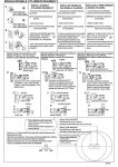
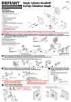
������������
For
Assistance
Call:
����
��
1-800-522-7336
����
��
����
��
����������
8 am - 5 pm, Monday - Friday, MST
Door Hardware
Installation Instructions
���
Double Cylinder Deadbolt
Carefully unpackage all components and place them within easy
reach. Find Figure #1 on Page 5 of these instructions for a listing
and drawing of each component. Detach Figure #1 and place
beside the components for easy reference. Check your door to
see if it has been prepped (pre-drilled) for installing a deadbolt.
If your door has been prepped for installation, start at Step 4. If
your door has not been prepped for installation, you will need a
#2 Phillips screwdriver, a drill, a 2-1/8” hole saw, 7/64” drill bit,
1” drill bit, chisel, pencil, tape and an awl (or nail).
Figure #2
D) Measure the thickness of the door. Doors vary in thickness
depending on the manufacturer. Determine the distance from
the center to the edge of the door (half the thickness of the
door). Using the awl (or nail), mark a point on the edge of the
door where the centerline pencil mark (from Step 1C) and the
center of the edge of the door meet (half the thickness), see
Figure #3.
������������������
������
�������
Step 1
Mark the Door
A) Find the Door Preparation Template which is included with
the instructions. Fold the template along the “edge-of-door”
line. Important: Before positioning the template, make sure
that you are aligning it on the non-hinged edge of the door.
Carefully position the template so that the narrow portion
of the template wraps around the edge of the door, and the
large portion of the template remains on the face of the
door, see Figure #2. Slide the template up or down on your
door so that the centerline is located at a height that is both
comfortable to use and attractive in appearance. Typically,
this will be approximately 36”-38” from the floor, see Figure
#2. Once you have chosen the height, tape the template to the
door.
B) Determine the backset of the deadbolt latch (Part #1) by
checking the marking on the deadbolt latch itself. If the latch
is not marked, measure the latch between points A and B to
determine the backset, as shown in Figure #2. The backset
will either be 2-3/8” or 2-3/4”. Once you know your backset,
find the point on the template where the centerline crosses the
vertical line that corresponds with the correct backset. Using
the awl (or nail) mark this point, making sure that it is marked
well enough to see on the door once the template is removed.
C) Follow the centerline around the edge of the door and using
a pencil, extend the centerline onto the edge of the door. The
mark should be horizontal to the floor. Once this mark is
made, you may remove the template from the door.
���
�����������
��������������
��������
����������
�������
���������
���������
��������
����������
�������
����������
��������
�����������������
�������������
�����������
���������
�������
������
������������������
Step 2
Drill the Door
����������
�������
���������
�������
����
��������������
Figure #3
A) Using the 2-1/8” hole saw, drill the cross bore hole centered
on the mark made on the face of the door from Step 1B. See
Figure #3. Important: To avoid splintering or marring the
door, drill from one side of the door until the pilot bit just
barely comes through the door. Then finish drilling from the
other side of the door, using the hole made by the pilot bit as
your guide.
B) Using the 1” bit, drill the edge bore hole centered on the mark
made on the edge of the door where the centerline and center
thickness met from Step 1D, see Figure #3. Important:
Make sure that you drill a full 3-1/2” deep, to accommodate
the overall length of the 2-3/8” latch. If you are using a 2-3/4”
backset latch, then the overall depth must be at least 3-3/4”.
Page 1 - PK158
Step 3
Step 5 - Install the Deadbolt
Mortise for the Faceplate
“Outside” Half
A) Using Figure #1 for reference, find the deadbolt faceplate
(Part #2). On the edge of the door, center the deadbolt
faceplate over the newly drilled edge bore hole, so that the
large hole in the deadbolt faceplate is centered over the 1”
edge bore hole. Align it so that the edges are parallel to the
edges of the door and roughly centered side-to-side. Mark
around the deadbolt faceplate with a pencil and remove from
door.
A) Using Figure #1 for reference, gather together both cylinder
assemblies (Part #4 & #6), both spin rings (Parts #5A), both
deadbolt escutcheons (Parts #5B), security ring (Part #16) and
2-3/4” machine screws (Part #7). Note: Not all designs use
spin rings. If your escutcheon is a Newport or Georgetown
design, then no spin ring is required. Except in rare cases such
as split finish designs, the interior and exterior escutcheons
will be interchangeable.
B) Using the chisel, score the outline of the deadbolt faceplate.
Next, chisel away the material within the outline to a depth
of 1/8”. When you are done, you should be able to insert the
deadbolt latch (Part #1), place the deadbolt faceplate over
the extended deadbolt (Part #1A), and have the deadbolt
faceplate be flush with the edge of the door.
C) Again, using the deadbolt faceplate as a template and the
awl as a marking tool, mark for the two screw holes that will
hold the deadbolt faceplate on the door. Remove the deadbolt
faceplate from the door to avoid marring the finish. Then,
drill the two screw holes using a 7/64” drill bit. Make sure the
holes are drilled at least 1” deep. Having too shallow a hole
can cause the screws to shear off.
Installing Your Lock
Step 4
Install the Latch
A) Insert a screwdriver into the deadbolt latch housing (Part #1)
and extend the deadbolt. Insert the deadbolt latch into the
edge bore hole, making sure that the “+” is oriented towards
the lower edge or bottom side of the deadbolt latch, see
Figure #4.
��������������
���������
���������
��������
����������
Interior Cylinder
Figure #5
Exterior Cylinder
B) Locate the exterior cylinder assembly, see Figure #5. This
can easily be identified by the Grandeur logo on it. Note: If
your design requires a spin ring, place the cylinder bar (Part
#4A) end of the cylinder assembly (Part #4) through the spin
ring, making sure that the narrower diameter of the spin
ring is closest to the key hole end of the cylinder assembly.
Next, insert the cylinder assembly (with spin ring if required)
through the deadbolt escutcheon (Part #5B) and finally add
the security ring as seen in Figure #6.
���������
����
����������
��������
����������
����������
������������
����������
��������
���������
���������
���������
��������
���������
���������
����������
�������������������
������������
���������
����������
����
��������������������
����������
Figure #4
B) Add the deadbolt faceplate over the deadbolt latch and make
sure that it can sit flush in the mortised out area. Note: Some
doors come prepared with rounded corners in the mortisedout area. If your door is prepared like this, simply use a chisel
to square off the corners so that the faceplate lies flush with
the edge of the door.
C) Install the 3/4” latch & strike wood screws (Part #3) to hold
the deadbolt latch and deadbolt faceplate in place.
Figure #6
C) From the outside of the door, insert the cylinder bar (Part
#4A) through the “+” in the deadbolt latch housing. Make
sure that the cylinder bar is oriented as shown in Figure
#7A or Figure #7B and that the deadbolt is still extended
from the edge of the door. From the inside of the door, if the
deadbolt extends toward the right, then the cylinder bar needs
to be oriented vertically Figure #7A. If the deadbolt extends
toward the left, then the cylinder bar needs to be oriented
horizontally, Figure #7B. IMPORTANT: If this step is not
done correctly, then the deadbolt will not work correctly!
Page 2 - PK158
Inside of Door
Deadbolt extends right
Inside of Door
Deadbolt extends left
I)
Figure #7A
Figure #7B
D) Make sure that the cross bore hole will be completely covered
by the outside escutcheon and that the Grandeur logo is
oriented correctly.
“Inside” Half
E) Locate the interior cylinder assembly (Part #6). This can
easily be identified because it has two holes drilled through
the face of the cylinder, see Figure #5. Assemble the interior
cylinder assembly and escutcheon as outlined in Step 5B.
F) Rotate the interior cylinder bar so that it is oriented in the
opposite orientation that you used in Step 5C. Holding the
exterior half of the deadbolt on the door, install the interior
half of the deadbolt. The driver bars will mate together in
the hub of the deadbolt latch. Depending on the thickness of
your door, the interior and exterior should be able to sit flush
against the door. If they do, go to Step 5I.
G) Adjustments must be made for thinner doors where the
deadbolt cannot sit flush against the door. Remove the interior
half of the deadbolt and set it aside. Holding the exterior half
in place, observe how much of the cylinder driver bar (Part
#4A) sticks through the latch, see Figure #7A & #7B. The
tangs on the driver bar are scored with marks to make this
easier. Count the marks showing through on a single tang and
if desired, mark the tang using a marker. Remove the exterior
half of the deadbolt. Using wire cutters, carefully snip off the
tangs at the last mark that was visible when it was installed
through the latch, being careful not to bend the tangs.
Reinstall the exterior half of the deadbolt to verify that the
tangs have been cut to the length which only leaves a small
amount still protruding from the latch. Follow these same
steps for the inside cylinder assembly.
H) Reinstall the deadbolt parts as outlined in Steps 5C - 5F. The
spin ring (or round escutcheon for Newport and Georgetown
designs) on the inside of the door, must be oriented with the
escutcheon slots at the 1 o’clock, 5 o’clock, 7 o’clock and 11
o’clock positions, a shown in Figure #8.
Locate the two 2-3/4” machine screws (Part #7). While
holding both the interior and exterior halves in place, insert
the machine screws through the interior cylinder assembly.
The screws will go through the latch and into the back
of the exterior cylinder assembly. Slowly screw in the
machine screws until nearly snug. Align the escutcheons for
appearance and fully tighten the screws.
J) Insert, turn, and remove the key in each side to make sure that
the deadbolt operates smoothly. If not, loosen the screws and
realign the escutcheons. With the screws not fully tightened,
turn the key on each side of the door to determine if both
sides operate smoothly. If only one side operates smoothly,
it is likely that the cylinder assembly driver bar tangs are too
long coming from the other side and are rubbing on the back
of the cylinder assembly. Using the wire cutters, trim them
back slightly and see if this fixes the issue. If not, call or
customer service department at 800-522-7336 for assistance.
K) Once you have tested the action of the deadbolt and it is
acceptable, move on to Step 6.
Step 6
Install the Interior Cylinder Faceplate
IMPORTANT: Before moving on to Step 6 it is critical that you
verify that the deadbolt is working properly. Insert the key
and turn it to both the locked and unlocked position and
remove the key in each position. Then repeat this for the
opposite side of the door. Only once you are satisfied with the
smooth operation of the deadbolt should you proceed.
A) Locate the interior cylinder faceplate (Part #8) and the plastic
faceplate jig (Part #9). Place the faceplate on the interior
cylinder, such that the logo and hole for the key align with the
cylinder. There are slots cut into the spin ring or escutcheon
that the tabs on the edge of the faceplate will align with, see
Figure #8.
B) Once the faceplate is aligned correctly, place the plastic
faceplate jig over the faceplate and press the faceplate into
position. Important: The faceplate must be pressed into place
evenly in order to avoid bending the faceplate. In most cases,
you will need to lightly tap the faceplate jig with a rubber
mallet or hammer to seat the faceplate properly.
Step 7
Installing the Door Reinforcer and Strike
Note: If door jamb is already drilled, go to Step 7E below.
����������
������
Figure #8
A) With the deadbolt in the unlocked position, close the door.
From the inside of the house, turn the key and identify where
the bolt is contacting the door jamb. Lightly mark this with
a pencil on the door jamb. Measuring in from the door stop
trim, identify the center mark where the bolt hole needs to
Page 3 - PK158
be drilled. Hint: If you cannot see the bolt clearly, or cannot
mark the jamb with a pencil because the door is closed, you
can cover the end of the bolt with a light amount of lipstick or
similarly visible material. When you turn the key, the lipstick
will mark the door jamb.
��������
���������� ����������
����������
����������
�����
�����
����
������������
����������
��������������
����������
���������������������
�����������
���������
Figure #9
B) Using a 7/8” drill bit, drill two holes centered 5/16” above
and below the center mark. These holes will overlap. Make
sure each one is at least 1-1/8” deep.
C) Clean out the hole (if needed) and insert the black dust box
(Part #10). Close the door carefully, making sure not to crush
the dust box. Make sure that the deadbolt and dust box line
up. If not, carefully enlarge the hole as needed.
D) Using the strike plate (Part #13), mark the area to be mortised
out for the dust box (Part #10), door frame reinforcer (Part
#11), and strike plate. Use a chisel to mortise this area and
make sure that once assembled, the strike plate sits flush to
the door jamb.
E) Place the door frame reinforcer over the dust box. Using the
door frame reinforcer as a guide, find the holes closest to the
outside of the house and drill two 7/64” x 3” deep holes for
the reinforcer screws.
F) Install the 3” wood screws (Part #12). Again, check to make
sure the deadbolt and reinforcer line up and that the deadbolt
can be locked.
G) Drill two 7/64” x 3/4” deep holes for the strike plate and
install the strike plate using the 3/4” latch and strike wood
screws (Part #3).
Congratulations! You are now
on your way to enriching your
life with
!
Page 4 - PK158
���������
����������
�����������
����������
����������
������������
����������
��������
����������
��������������
����������
�������������
������������
������
����������
��������
����������
����������
������������
����������
���������
��������
��������
���������
��������
���������
���������
��������
����������
��������������
���������
�������������
����������
Figure #1
���������
��������
��������
���������
��������
���������
���
���������
Page 5 - PK158
������
�������
������
���������
��������
��������
���������
���������
��������
����������
����������
���������
����������