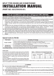
1
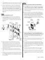
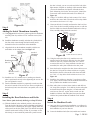
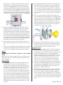
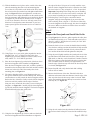
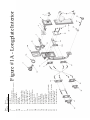
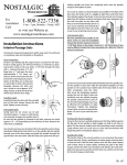
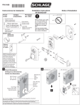
Door Hardware
Installation Instructions
Handleset - Single Cylinder Version
Carefully unpackage all components and place them within easy
reach. Find Figure #1A and Figure #1B (exploded drawings
with parts listing) at the back of these instructions. Figure #1A
is for a longplate style interior, and Figure #1B is for a rosette
(round) style interior. Use Part #19 to determine which of these
two figures is appropriate for your installation and discard the
other to avoid confusion. Place the appropriate Figure #1 for your
installation beside the components for easy reference. For the
balance of these instructions, we will only refer to this exploded
drawing as Figure #1.
You will need a #2 Phillips screwdriver for installation of your
new doorsets. If the door is not pre-drilled, you will also need a
2-1/8” hole saw, a 7/64” drill bit, 7/32” drill bit, 5/16” drill bit,
7/8” drill bit, and 1” drill bit (spade or forstner style), a chisel, a
pencil and an awl (or nail). If your door is pre-drilled start at Step
2.
Step 1
Door Preparation
A) Find the Entry Door Preparation Templates. Determine
if your door is beveled (see illustration on templates). If so,
choose the appropriate Entry Door Preparation Template and
fold along line B to match the illustration. If your door is
not beveled, choose the appropriate Entry Door Preparation
Template that will mount on the outside of your door and
fold along line B.
B) Carefully position the template on the outside of the door
so that the line marked A is approximately 36”-38” from the
floor, depending on preference of doorknob height. Make
sure that the corner of the door is lined up with the fold (line
B) and tape the template to the door. IMPORTANT—If your
door is prepped with a 2-1/8” hole for the doorknob, match
line A with the center of the existing doorknob hole.
C) Determine if your “backset” is 2-3/8” or 2-3/4”. If your
door is prepped for a lock, the backset is the distance from
the edge of the door to the center of the cross-bore hole
(see Figure #2). If your door is not prepped, then find the
handleset latch (Figure #1, Part #14). Measure the distance
from the flange to the center of the star-shaped hub. The
distance will be slightly under 2-3/8” or 2-3/4” to allow for
adding a faceplate. See Figure #2. If your backset is 2-3/8”,
use line C on the template. If your backset is 2-3/4”, use line
D.
For
Assistance
Call:
8 am - 5 pm, Monday - Friday, MST
or visit our Website at: www.grandeur-nw.com
1-800-522-7336
��
D) Using the awl (or a nail), mark the three intersecting points
on the template as indicated below, making sure the door is
clearly marked:
2-3/8″ Backset
2-3/4″ Backset
or
Where lines E & C cross
Where lines E & D cross
Where lines A & C cross
Where lines A & D cross
Where lines F & C cross
Where Lines F & D cross
E) Measure the thickness of your door. Most exterior doors
are 1-3/4”, 2” or 2-1/4” thick. Once you have measured the
thickness, mark the points on the edge of the door where lines
A and E intersect with your appropriate door thickness line.
F) With the template still on the door, close the door. Using
a pencil, lightly mark on the door jamb where lines A and
E meet the jamb. Find the Door Jamb Template and fold
along line BB. Once the template has been folded, place it
against the door jamb so that the folded edge matches up with
where the edge of the door sits when closed. Match lines AA
and EE to the marks you made from lines A and E. Once
aligned, tape the Door Jamb Template to the door jamb. Find
the four points where lines 1, 2, 3, & 4 cross the correct door
thickness. Using the awl (or a nail), mark these four points on
the jamb.
G) Verify that all marks can be clearly seen on the door and door
jamb and remove both templates.
H) Using Figure #3 and the marks made in Step 1D as a
reference, drill the two 2-1/8” cross-bore holes using a hole
saw. IMPORTANT—To avoid damaging the door, drill from
one side until the pilot bit comes through the door. Then
finish drilling from the other side, using the pilot hole as your
guide. IMPORTANT—Always drill as straight or level as
possible to ensure proper door preparation.
I)
Using Figure #3 as reference and the marks made in Step 1E,
drill the two 1” edge-bore holes. Make sure that you drill a
full 3-7/8” deep for 2-3/8” backset, or 4-3/8” deep for a 23/4” backset, which will extend beyond the cross-bore holes.
���������
�����
������������
����������
�����
������������
Flange
Star-shaped hub
Figure #2
Figure #3
Page 1- PK161
J) Using Figure #3 and the mark made in Step 1D as reference,
drill one 7/32” hole all the way through the door at point M.
K) Using the faceplates (Parts #2 & #15) as templates and a
pencil to mark with, line up the faceplate for the deadbolt
(Part #2) with the top edge-bore hole on the door and lightly
mark a line around the faceplate. Then, using a chisel,
mortise out a 1/8” deep area to allow the faceplate to sit flush
with the edge of the door. Repeat this step with the faceplate
for the latch (Part #15) on the bottom edge-bore hole. See
Figure #3.
Step 2
Install the Deadbolt Latch
A) Find the Deadbolt Latch (Part #1). Use a screwdriver to
extend the deadbolt (Part #1A). Insert the latch into the
top edge-bore hole, making sure that the latch is oriented
correctly with the “+” on the lower portion of the latch. See
Figure #4.
Step 3
Install the “Outside” Half of the Deadbolt
A) Using Figure #1 for reference, gather together the cylinder
assembly (Part #4), spin ring on longplate installations (Part
#5A), the escutcheon (Part # 5 or #5B), the deadbolt adaptor
plate (Part #6), the security ring (Part #16), and two 2-3/4”
machine screws (Part #7). Part #5A is not used or required for
a rosette installation.
B) Place the spin ring over the cylinder driver bar (Part #4A)
end of the cylinder, making sure that the narrower edge of
the spin ring is closest to the key hole end of the cylinder.
Insert the cylinder assembly through the spin ring and
escutcheon. On the back of the escutcheon, slip the narrow
end of the security ring (Part #16) onto the cylinder assembly
as shown in Figure #5.
Deadbolt
(Part #1A)
����������
�������������
Deadbolt
Latch
(Part #1)
Deadbolt
Faceplate
(Part #2)
����������
���������������
���
Handleset
Latch
(Part #14)
���
Figure #5
Latch
Bolt
(Part #14A)
Figure #4
Rotate latch
bolt so curved
surface faces
door jamb.
Latch
Faceplate
(Part #15)
3/4” Latch
& Strike
Wood
Screws
(Part #3)
B) Place the faceplate for the deadbolt (Part #2) over the
deadbolt and make sure that it sits flush in the mortised
out area on the edge of the door. Note: some doors come
prepped with rounded corners in the mortised out area. If
your faceplate does not sit flush, simply use a chisel to square
off the corners so that the faceplate for the deadbolt sits flush
with the edge of the door.
C) Drill the latch screw holes with 7/64” drill bit at least 3/4”
deep. Having too small a hole can cause the screws to shear
off.
D) Install two 3/4” latch & strike wood screws (Part #3) through
the faceplate and deadbolt latch to hold them both in place, as
shown in Figure #4. TIP: for ease of installation, add soap to
the screw threads.
C) From the outside of the door, insert the cylinder driver bar
(Part #4A) through the “+” in the deadbolt latch housing,
making sure that the driver bar is oriented vertically with
the deadbolt extending from the edge of the door. If done
correctly, the outside assembly should hold itself in place
temporarily.
D) Make sure that the cross bore hole will be completely covered
by the escutcheon and that the Grandeur logo is oriented
correctly.
E) On the inside of the door, place the deadbolt adaptor plate
(Part #6) so that the beveled screw holes face away from the
door and line up with the corresponding holes on the cylinder
assembly. Screw in the two 2-3/4” machine screws (Part #7)
to hold the outside assembly in place, see Figure #6. Do not
fully tighten yet.
F) Align the escutcheon and cylinder with the door edge and
snug the two machine screws down. Do not over tighten.
G) Using the key, unlock and re-lock the latch to make sure that
the action is smooth. If the screws have been over tightened,
the latch may bind. Once the action is acceptable, move on to
Step 4.
Page 2 - PK161
the door is closed, you can cover the end of the bolt with a
light amount of lipstick or similarly visible material. When
you turn the thumbturn, the lipstick will mark the door
jamb. Measuring in from the “door stop trim”, identify the
center mark where the bolt hole needs to be drilled, see
Figure #8.
B) Using a 7/8” drill bit, drill two holes centered 5/16” above
and below the center mark. These holes will overlap. Make
sure each one is at least 1-1/8” deep.
Figure #6
Step 4
Adding the Inside Thumbturn Assembly
C) Clean out the hole (if needed) and insert the dust box (Part
#10). Close the door carefully, making sure not to crush the
dust box. Make sure that the deadbolt and dust box line up.
If not, carefully enlarge the hole as needed.
��������
���������� ����������
����������
����������
A) Using Figure #1 for reference, gather together the thumbturn
assembly (Part #8), and the two 5/8” machine screws (Part
#9).
�����
�����
����
B) Install the thumbturn assembly such that the cylinder driver
bar (Part #4A) comes through the latch housing and is
inserted into the slot on the back of the thumbturn.
C) Align the holes on the thumbturn assembly with the two
small holes on the adaptor plate. See Figure #7.
��������
�������������
��������
���������
���������
��������
���������
����
������������������
���������
����
��������������
���������
��������
����������
Figure #7
D) Install the two 5/8” machine screws, making sure that the
plate is positioned correctly before tightening the screws. Do
not over-tighten the screws.
E) Turn the thumbturn and the key separately to make sure that
the action is smooth. If the screws have been over-tightened,
the latch may bind. Once the action is acceptable, move on to
Step 5.
Step 5
Installing the Door Reinforcer and Strike
Note: If door jamb is already drilled, go to Step 5E below.
A) With the deadbolt in the unlocked position, close the door.
From the inside of the house, turn the thumbturn and identify
where the bolt is contacting the door jamb. Lightly mark this
with a pencil on the door jamb. Note: This should correspond
with the marks made in Step 1F. Hint: If you cannot see the
bolt clearly, or cannot mark the jamb with a pencil because
������������
����������
��������
������
���������� ������������
�����������������������������
Figure #8
D) Using the strike plate (Part #13), mark the area to be
mortised out for the dust box (Part #10), the door frame
reinforcer (Part #11), and the strike plate. Use a chisel
to mortise this area 3/16” deep and make sure that once
assembled, the strike plate sits flush to the door jamb.
E) Insert the dust box and place the door frame reinforcer over
the dust box. Using the door frame reinforcer as a guide,
find the holes closest to the outside of the house and drill
two 7/64” x 3” deep holes for the reinforcer screws. See
Figure #8.
F) Install the door reinforcer using the 3” wood screws (Part
#12). Again, check to make sure the deadbolt and reinforcer
line up and that the deadbolt can be locked.
G) Place strike plate over door frame reinforcer and drill two
3/4” deep holes (using the 7/64” drill bit) for the strike plate
and install the strike plate using the 3/4” latch and strike
wood screws (Part #3). Again, check to make sure the
deadbolt, reinforcer and strike plate line up and are flush
with the door jamb and that the deadbolt can be locked.
Step 6
Install the Handleset Latch
A) Once your door is prepped for installation, you will need a
#2 Phillips screwdriver, a drill, and a 4” x 7/64” drill bit for
the installation of your new doorsets.
B) Locate the handleset latch (Part #14) and the anti-rotation
Page 3 - PK161
block (Part #27). The anti-rotation block is only used with
a Rosette interior. Insert the anti-rotation block into the
cross bore hole (Figure #3) so that the arrow on the block
is pointing toward the edge of the door. Install the handleset
latch into the edge bore hole (Figure #3), making sure that
it is correctly inserted through the anti-rotation block. When
installed correctly, the star-shaped hub in the latch should be
centered in the hole of the anti-rotation block, see Figure #9.
�����������
���
�������������
�����
����������
�����������������
�����
����������
�����������
Figure #9
C) Determine which direction the door will swing when it is
being opened. Rotate the latch bolt (Part #14A) so that the
flat edge of the bolt faces toward the direction the door
swings when being opened (and the round edge towards the
doorjamb). Once oriented correctly, place the faceplate (Part
#15) over the latch bolt, locking the latch bolt orientation.
Note: some doors come prepped with rounded corners in the
mortised out area. If your door is prepped like this, simply
use a chisel to square off the corners so that the faceplate for
the handleset sits flush with the edge of the door.
E) Drill the latch screw holes with 7/64” drill bit at least 3/4”
deep. Having too small a hole can cause the screws to shear
off.
F) Install two 3/4” latch & strike wood screws (Part #3) through
the faceplate and handleset latch to hold them both in place.
TIP: for ease of installation, add soap to the screw threads.
Step 7
Installing the Exterior Grip-set and Inside
Trim
Determine if you will be installing a rosette or a longplate on the
inside of the door, and go to either Step 7A for Rosettes or Step
7E for Longplates.
Rosette Version
A) Using Figure #1 for reference, gather together the exterior
handleset (Part #17), the inside rosette assembly (Part
#19), the lower mounting screw (Part #23) and the rosette
mounting screws (Part #20). Note that there are two lengths
of rosette screws provided, one 1-1/2” pair and one 2”
pair. The majority of doors will use the shorter screws (11/2”), so try these first and only use the longer screws if the
shorter ones do not work. Insert one of the screws through
the top hole in the rosette assembly and set this aside within
easy reach. Carefully place the handleset in position on the
outside surface of the door, such that the handleset spindle
(Part #17A) is seated in the star-shaped hub of the latch, see
Figure #10. When seated correctly, you will be able to hold
the handleset in place and depress the thumbpiece to retract
the latch.
B) While holding the handleset in position on the outside of the
door, install the lower mounting screw (Part #23) through
the screw cover adaptor (Part #22) and tighten snugly, but
do not overtighten. If your door thickness is 1-3/4” then the
2-1/4” long screw should be sufficient. Any door thicker than
1-3/4” will require the 2-1/2” screw length to be used. Thread
the mounting screw cover (Part #24) onto the screw adaptor
cover.
C) Place the rosette assembly in position on the inside of the
door, and insert the rosette mounting screw (Part #20) into the
top screw boss on the back of the handleset, see Figure #10.
Tighten and screw down until almost snug. Insert and tighten
down the second rosette screw into the lower screw boss.
Align the handleset on the outside of the door for appearance
and snug down both rosette screws. Do not overtighten. If
your interior set is a knob, go to Step 8.
�����������������������
�������������
�����������������
���������
Figure #10
D) If your interior set includes a lever see Figure #11 for lever
orientation. Your lever will only rotate in one direction. It is
designed to rotate downward. If your lever rotates upward,
please call customer service at 1-800-522-7336.
Longplate Version
E) Locate the exterior handleset (Part #17), the mounting plate
(Part #18), the lower mounting screw (Part #23) and the
mounting plate screws (Part #21). Insert one of the mounting
plate screws through the top hole in the mounting plate
and set this aside within easy reach. Note that there are two
lengths of mounting plate screws provided, one 1-1/4” pair,
and one 1-3/4” pair. The majority of doors will use the
shorter screws (1-1/4”), so try these first and only use the
longer screws if the shorter ones do not work. Carefully
place the exterior handleset in position on the outside surface
of the door, such that the spindle (Part #17A) is seated in the
star-shaped hub, see Figure #10. When seated correctly, you
will be able to hold the handleset in place and depress the
thumbpiece to retract the latch bolt.
F) While holding the handleset in position on the outside of the
door, install the lower mounting screw (Part #23) through
the screw cover adaptor (Part #22) and tighten snugly, but
do not overtighten. If your door thickness is 1-3/4” then the
2-1/4” long screw should be sufficient. Any door thicker than
1-3/4” will require the 2-1/2” screw length to be used. Thread
the mounting screw cover (Part #24) onto the screw adaptor
cover.
Page 4 - PK 161
G) With the handleset now in place on the outside of the door,
place the mounting plate (Part #18) and mounting plate
screw (Part #21) in position on the inside of the door, insert
the screw into the top retention boss and tighten until almost
snug. See Figure #11. Insert and tighten the second screw
into the lower boss. Align the handleset on the outside of the
door for appearance and tighten the screws until snug. Do not
overtighten. If your interior set includes a lever see Figure
#11 for lever orientation. Your lever will only rotate in one
direction. It is designed to rotate downward. If your lever
rotates upward, please call customer service at 1-800-5227336.
���������
�����
Correct Lever Orientation
(Lever Rotates Downward)
L) Following Step 7I and 7J again, re-attach the interior
longplate, using the clear alignment jig to protect the door
from scratching. Then, using the 1” wood screws (Part #20),
secure the longplate to the door snugly, but do not overtighten
the screws. Make sure that the screwdriver does not scratch
the doorknob or longplate.
Step 8
Prepare the Doorjamb and Install the Strike
����������
������
Door
Edge
Incorrect Lever Orientation
�������������������������
������������������������
����
���������
���������
Figure #11
H) Using Figure #1 as your guide, gather together the interior
longplate (Part 19), 1” wood screws (Part #20), clear
alignment jig (provided), Phillips screwdriver, drill, awl (or
nail), and the 4” x 7/64” drill bit (provided).
I)
the edge of the door. Using an awl (or nail), mark the screw
holes on interior longplate and remove it from the door. Drill
the screw holes 3/4” deep, using the 4” x 7/64” bit provided.
Important: Depending on the design that you are installing
there will either be two or four screw holes in each plate. All
screws must be installed to secure the longplate to the door.
Place the clear alignment jig on the inside of the door where
the interior longplate will be installed, see Figure #12.
Place the interior longplate on the door, so that the spindle is
inserted into the star-shaped hub of the latch and the retention
bosses nest in the wide end of the teardrop slots in the
mounting plate, see Figure #11.
J) The interior longplate will be out of alignment when you
first get the retention bosses into the teardrop slots. When the
retention bosses are fully seated, the interior longplate will be
flush to the face of the door. Gently twist the interior longplate
clockwise until it is parallel with the edge of the door,
being sure not to scratch the door when you are twisting the
longplate, see Figure #12. Carefully slip the clear alignment
jig out from under the interior longplate. The interior longplate
should hold itself on the door at this point.
A) Using Figure #1 for reference, gather together the strike plate
for handleset (Part #26), two 1” latch and strike wood screws
(Part #3), a drill, 1” drill bit, the awl (or nail), 4″x7/64” drill
bit, the pencil and chisel.
B) Rotate the knob or lever to retract the latch bolt and carefully
close the door, making sure that the latch bolt is fully retracted
and does not scratch the doorjamb. Slowly release the knob/
lever and let the latch bolt extend against the doorjamb.
C) Using the pencil, lightly mark the door jamb at the level of the
top and bottom of the latch bolt (Part #14a). These need to be
light marks, so that they can be erased later if needed. Turn the
knob/lever again to retract the latch bolt and re-open the door.
Now extend the marks so that they are approximately 3/4”
from the edge of the door stop trim where the door stops when
it is closed, See Figure #13.
D) Repeat Step 8B, and verify that the latch bolt is falling
between the two marks.
E) Measure the thickness of the door. Take half of the door
thickness and measure that same distance from the edge of the
door stop trim where the door stops when it is closed. Mark
on the door jamb this distance halfway between the two lines
from Step 8C, see Figure #13.
�����
����
����������
����
����������
�������
���������������
���������������
����������
�������������������
����������
�������
�����
���������
���������
���������
������
Figure #13
�������������
Figure #12
K) Using the clear alignment jig, check to make sure that both
the interior longplate and exterior handleset are aligned to
F) Using the awl, mark where the point that is halfway between
the two lines made in Step 8C crosses the line marked in Step
8E.
Page 5 - PK 161
G) Using a 1” drill bit, drill a hole centered on the mark from
Step 8F. Make sure the hole is at least 5/8” deep. Clean out
any sawdust from the hole.
H) Using the strike plate for handleset (Part #26) as a template,
center the strike over the 1” hole, mark a line around it in
pencil and remove from doorjamb.
I)
Using the chisel, score the outline of the strike. Next, chisel
away the material within the outline to a depth of 1/16”.
When you are done, you should be able to place the strike
in the mortised out area and it should be flush with the
doorjamb.
J) Again, using the strike as a template and the awl as a marking
tool, mark the two screws holes that will hold the strike on the
door. Remove the strike from the doorjamb to avoid marring
the finish. Then, drill the two screw holes using the 4” x
7/64” drill bit. Make sure the holes are drilled at least 3/4”
deep. Having too small or too shallow of a hole can cause the
screws to shear off.
K) Install the dustbox and fasten the strike in place using two
3/4” latch & strike wood screws (Part #3) Hint: Coating the
screw threads with a small amount of soap (liquid or bar soap)
will make installation easier.
Congratulations! You are now
on your way to enriching your
life with
!
Page 6 - PK 161
����� �������������
��������������������������
��
����������������������
����
����������������
��
������������������������������
��
�������������������������������������������
��
�������������������������
���
���������������������������
���
�����������������
���
������������������
��
������������������������������
��
������������������������������
��
��������������������������
��
�������������������������������
���
����������������������������
���
�����������������������������
���
��������������������������
���
���������������������������������
���
�����������������������
����
�������������������
���
���������������������������
���
���������������������
���
�������������������������
����
�������������������������
���
����������������������
����������� ��������������������������
���
����������������������
���
�����������������������������������������
���
���������������������������
���
����������������������������������������
���
����������������������������
���
�����������������������������
���
����������������������������������
��������������������������������
����� �������������
��������������������������
��
����������������������
����
����������������
��
������������������������������
��
�������������������������������������������
��
�������������������������
���
���������������������������
��
������������������
��
������������������������������
��
������������������������������
��
��������������������������
��
�������������������������������
���
����������������������������
���
�����������������������������
���
��������������������������
���
���������������������������������
���
�����������������������
����
������������������
���
���������������������������
���
���������������������
���
�������������������������
����
�������������������������
���
�������������������������������������������
����������� ������������������������
���
�������������������������������������������
���
�������������������������������������������
���
���������������������������
���
����������������������������������������
���
����������������������������
���
�����������������������������
���
����������������������������������
���
���������������������������
������������������������������