1
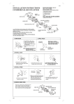
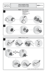
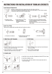
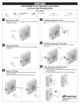
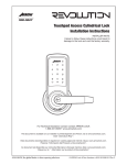
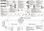
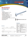
EA1
EA1
INSTRUCTIONS FOR INSTALLATION OF ENTRANCE LOCKS
IN NEW DOORS OR THE REPLACEMENT OF EXISTING LOCKS
FOR USE ON DOORS 1-3/8" TO 1-3/4"
(35mm~45mm) THICK
TOOLS REQUIRED FOR REPLACEMENT
INSTALLATION:
1 phillips head screwdriver
TOOLS REQUIRED FOR NEW INSTALLATION
1 phillips head screwdriver
1 2-1/8" (54mm) hole saw
1 1" (25.4mm) drill bit
1 chisel
ILLUSTRATIONS ARE SHOWN WITH
ENTRANCE MODELS. INSTALLATION IS
SAME FOR PRIVACY AND PASSAGE
MODELS AS WELL.
KEY
FOLLOW ALL STEPS FOR REMODELING OR
NEW CONSTRUCTION.
CYLINDRICAL CASE
FOLLOW STEPS 3C,4C,5,6,7,8,9 and 10
FOR DO-IT-YOURSELF REPLACEMENT
AFTER REMOVAL OF EXISTING LOCK.
INSIDE SLEEVE
SPINDLE
INSIDE MOUNTING PLATE
OUTSIDE KNOB
OUTSIDE ROSE
PUSH BUTTON
REPLACING EXISTING LOCKS:
Before beginning, measure from
center of lock to door edge in order
to check length of backset on
existing lock. The backset length
of new lock is stated clearly on
front of package.
If backset size is the same,
you'll have to replace
lock with proper size
backset.
LATCH RETRACTOR
LATCH UNIT
GUARDBOLT
LATCHBOLT
MOUNTING SCREWS
SCREW HOLE
LATCH FACE
INSIDE ROSE
INSIDE KNOB
INSTALLATION INSTRUCTIONS
1. MARK DOOR
2. DRILL HOLES
Start approximately 36"
(914mm) from floor. Fold
and apply template to edge
of door and mark center of
door edge as indicated on
template. Mark center hole
on door face through guide
on template.
(NOTE: Backset on door face must be
same as backset of lock.)
MARK FOR 1"
(25.4mm)
HOLE IN
DOOR EDGE
MARK FOR 2-1/8"
(54mm) HOLE ON
DOOR FACE
Drill 2-1/8" (54mm) hole through door
face as marked for lockset.
It is recommended that holes be drilled
from both sides to prevent splitting.
Drill 1" (25.4 mm) hole in center of
door edge for latch.
2-1/8" (54mm)
HOLE
1" (25.4mm)
3. INSTALL LATCH
A
Insert latch in hole keeping it
parallel to face of door. Mark
outline and remove
latch.
B
Chisel 5/32" (4mm)
deep or until latch
face is flush with
door edge.
C
Insert latch and tighten
screws.
(NOTE: Latchbolt bevel
must face to
closing
direction.)
4. INSTALL STRIKE
A
Close door until latchbolt touches jamb to
locate strike in jamb and center line of strike.
Open door and extend line from mark to door
stop. Measure one half of door thickness from
door stop and vertically mark drill point center
for strike.
EA1
C
B
Drill 1" (25.4mm)
hole 1/2" (12.7mm)
deep in door jamb
on drill point for
strike.
CAUTION: To ensure proper lockset function.
Hole in jamb must be drilled a full
1/2" (12.7mm) deep.
GUARD BOLT
Cut out jamb 1/16"
(1.5mm) deep for
strike. Tighten screws.
STRIKE
Guardbolt stops against
strike, as illustrated,
preventing forcing when
door is closed. Adjustable
tang on strike permits
bending in or out to
eliminate too loose fit between door and
door stop.
EA1
EA1
EA1
5. REMOVE INSIDE TRIM
a
6. ADJUST OUTSIDE ROSE
Use nail end of wrench provided to depress
inside knob catch in
hole of inside sleeve
collar and slide knob or
in side lever off spindle.
Adjust lock to fit door thickness by
rotating outside rose.
Lock will fit all doors 1-3/8" to 1-3/4"
(35mm~45mm) thick.
Latch unit must be in place before
installing lock. Be sure lock housing
engages with latch prongs and
retractor interlocks with latch tail.
DOOR
b
Depress spring attached
to inside rose. Insert nail
end of wrench into slot to
remove inside rose plate.
7. INSTALL LOCK
c
CENTER LINE
Remove inside rose and mounting plate.
8. INSTALL INSIDE ROSE
9. INSTALLATION OF INSIDE KNOB
A. FOR WOODEN DOOR
Tighten machine screws securely to install
mounting plate.
Press rose onto mounting plate.
Be sure to fit rose in recess of mounting plate.
B. FOR METAL DOOR
MOTE: Make sure that mounting plate fit
horizontally into slots notched in door.
IMPORTANTAlign lug on knob with narrow
slot on side of spindle and push knob
all the way in until knob catch clicks
into slot on knob.
Otherwise knob will jamb on shaft.
NOTCH
SLOT
Tighten machine
screws securely
LUG
NOTCH
Tighten machine screws securely
10. RIGHT KEY HOLE POSITION
Upon installation of the lock, it may happen
that key hole faces upward or downward as
shown in the following drawing.
It is advisable to correct all key hole to be
facing downward.
11. IN ORDER TO ADJUST THE ABNORMAL STATE OF THE KEY HOLE FACING
UPWARD, THE KNOB MUST BE PULLED OUT AND INSTALLED AGAIN.
THE METHOD OF INSTALLATION IS DESCRIBED AS BELOW D.
a
b With the other hand,
First turn the knob
clockwise until the
knob catch appears
in the small hole.
turn the key
counterclockwise
within the limit of
30°~90°
c
DOWNWARD
CORRECT
X
UPWARD
INCORRECT
d
Install again
according to
the correct
direction.
Using a small nail
to press the knob
catch and pull the
knob out.
TEMPLATE
54mm (2-1/8")
BACKSET 70mm (2-3/4")
Fit here on door edge
BACKSET 60mm (2-3/8")
51 45
40 35
32
5.5mm (7/32") x2 HOLE
2" 1-3/4" 1-9/16" 1-3/8" 1-1/4"
64mm (2-33/64")
Mark 1" (25.4mm) hole at center of
door edge.
EA1
8mm (5/16") DEEP
FOR METAL DOOR ONLY
Rev. 10/21/2008