1
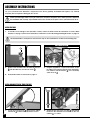
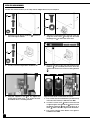
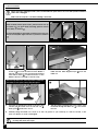
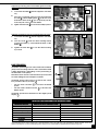
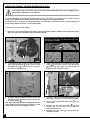
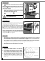
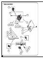
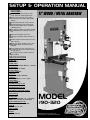
SETUP & OPERATION MANUAL
FEATURES
Designed for excellent results, for both
wood and metal cutting applications.
17” WOOD / METAL BANDSAW
Select between metal & wood cutting
speed ranges with a simple belt position
change.
Dynamically balanced cast-iron wheels.
Solid, high quality, precision-machined,
ribbed cast-iron table with 5° left and 45°
right tilting action.
New and improved! Now includes upgraded 90-075B deluxe Excalibur rip fence system.
Quick release blade tension lever.
Dual/opposing blade guide bearing system.
2 built-in 4" diameter dust chutes for better
dust collection.
Quick easy adjust variable speed control
and digital display for blade speed in
FEET/MIN.
Large paddle style stop switch with lockout safety pin and lock-out switch with key
for main power.
Miter gauge, laser line marker and worklight included.
SPECIFICATIONS
WHEEL SIZE
17” (430 MM)
WHEEL SPEED
WOOD: 122 - 810 RPM / METAL: 23 - 146 RPM
BLADE WIDTH
1⁄8” TO 1” (3 TO 25.4 MM)
BLADE LENGTH
131 1⁄2” (3340 MM)
TABLE SIZE
23 1⁄2” X 17” (600 X 430 MM)
TABLE TILT
0° TO 45° (RIGHT) / 0° TO 5° (LEFT)
TABLE HEIGHT
39 3⁄4” (1010 MM)
MAXIMUM DEPTH OF CUT
11 1⁄2” (295 MM)
MAXIMUM WIDTH OF CUT
16 1⁄4” (410 MM)
MAXIMUM CUTTING (RIP FENCE)
14 5⁄8” (370 MM)
DUST PORT (2)
4” (102 MM)
BLADE SPEED
WOOD 540 - 3600 FPM (165 - 1100 MPM)
METAL 100 - 650 FPM (30 - 200 MPM)
BASE DIMENSIONS (L X W)
29 1⁄2” X 17 3⁄4” (749 X 451 MM)
MOTOR
2 HP, 220 V, 3 PH, 7 A)
INPUT POWER
220 V, 1 PH
WEIGHT
440 LBS (200 KG)
MODEL
#90-320
VERSION 4_Revision 2 - August 16, 201
© Copyright General® International 08/2012
GENERAL® INTERNATIONAL
8360 Champ-d’Eau, Montreal (Quebec) Canada H1P 1Y3
Telephone (514) 326-1161 • Fax (514) 326-5555 • www.general.ca
THANK YOU for choosing this General
International model 90-320 - 17” Wood
/ Metal Bandsaw. This bandsaw has been carefully tested and inspected before shipment and
if properly used and maintained, will provide you with years of reliable service. For your safety, as well as to ensure optimum performance and trouble-free operation, and to get the most
from your investment, please take the time to read this manual before assembling, installing
and operating the unit.
®
The manual’s purpose is to familiarize you with the safe operation, basic function, and features
of this bandsaw as well as the set-up, maintenance and identification of its parts and components. This manual is not intended as a substitute for formal woodworking instruction, nor to
offer the user instruction in the craft of woodworking. If you are not sure about the safety of
performing a certain operation or procedure, do not proceed until you can confirm, from
knowledgeable and qualified sources, that it is safe to do so.
Once you’ve read through these instructions, keep this manual handy for future reference.
Disclaimer: The information and specifications in this
manual pertain to the unit as it was supplied from the
factory at the time of printing. Because we are committed to making constant improvements, General®
International reserves the right to make changes to
components, parts or features of this unit as deemed
necessary, without prior notice and without obligation to
install any such changes on previously delivered units.
Reasonable care is taken at the factory to ensure that
the specifications and information in this manual corresponds with that of the unit with which it was supplied.
However, special orders and “after factory” modifications may render some or all information in this manual
inapplicable to your machine. Further, as several generations of this model of bandsaw and several versions of
this manual may be in circulation, if you own an earlier
or later version of this unit, this manual may not depict
your machine exactly. If you have any doubts or questions contact your retailer or our support line with the
model and serial number of your unit for clarification.
GENERAL® & GENERAL® INTERNATIONAL WARRANTY
All component parts of General®, General® International and Excalibur by General
International ® products are carefully inspected during all stages of production and each unit
is thoroughly inspected upon completion of assembly.
Limited Lifetime Warranty
Because of our commitment to quality and customer satisfaction, General® and General®
International agree to repair or replace any part or component which upon examination,
proves to be defective in either workmanship or material to the original purchaser for the life
of the tool. However, the Limited Lifetime Warranty does not cover any product used for professionnal or commercial production purposes nor for industrial or educational applications.
Such cases are covered by our Standard 2-year Limited Warranty only. The Limited Lifetime
Warranty is also subject to the “Conditions and Exceptions” as listed below.
Standard 2-Year Limited Warranty
All products not covered by our lifetime warranty including products used in commercial,
industrial and educational applications are warranted for a period of 2 years (24 months) from
the date of purchase. General® and General® International agree to repair or replace any
part or component which upon examination, proves to be defective in either workmanship or
material to the original purchaser during this 2-year warranty period, subject to the “conditions
and exceptions” as listed below.
To file a Claim
To file a claim under our Standard 2-year Limited Warranty or under our Limited Lifetime
Warranty, all defective parts, components or machinery must be returned freight or postage
prepaid to General® International, or to a nearby distributor, repair center or other location
designated by General® International. For further details call our service department at 1-888949-1161 or your local distributor for assistance when filing your claim.
Along with the return of the product being claimed for warranty, a copy of the original proof
of purchase and a “letter of claim” must be included (a warranty claim form can also be used
and can be obtained, upon request, from General® International or an authorized distributor)
clearly stating the model and serial number of the unit (if applicable) and including an explanation of the complaint or presumed defect in material or workmanship.
CONDITIONS AND EXCEPTIONS:
This coverage is extended to the original purchaser only. Prior warranty registration is not
required but documented proof of purchase i.e. a copy of original sales invoice or receipt
showing the date and location of the purchase as well as the purchase price paid, must be
provided at the time of claim.
Warranty does not include failures, breakage or defects deemed after inspection by General®
or General® International to have been directly or indirectly caused by or resulting from;
improper use, or lack of or improper maintenance, misuse or abuse, negligence, accidents,
damage in handling or transport, or normal wear and tear of any generally considered consumable parts or components.
Repairs made without the written consent of General® Internationallwill void all warranty.
TABLE OF CONTENTS
Rules for safe operation . . . . . . . . . . . . . .5-6
Electrical requirements . . . . . . . . . . . . . . .7
Grounding instructions . . . . . . . . . . . . . . . . . . . . . . .7
Circuit capacity . . . . . . . . . . . . . . . . . . . . . . . . . . . . .7
Extension cords . . . . . . . . . . . . . . . . . . . . . . . . . . . . .7
Blade speed control . . . . . . . . . . . . . . . . . . . . . . . .22
Changing blade speed range - switching from
wood to metal cutting . . . . . . . . . . . . . . . . . . . . . .43
Operating instructions . . . . . . . . . . . . .25-26
Lifting and handling the machine . . . . . . . .9
Connecting to a dust collector . . . . . . . . . . . . . . .25
Checklist before starting . . . . . . . . . . . . . . . . . . . . .25
Operations step-by-step . . . . . . . . . . . . . . . . . . . . .25
Using the rip fence . . . . . . . . . . . . . . . . . . . . . . . . .26
Using the miter gauge . . . . . . . . . . . . . . . . . . . . . .26
Cutting curves . . . . . . . . . . . . . . . . . . . . . . . . . . . . .26
Cutting circles . . . . . . . . . . . . . . . . . . . . . . . . . . . . .26
Unpacking . . . . . . . . . . . . . . . . . . . . . . . .10
Periodic Maintenance . . . . . . . . . . . . . . . .27
List of contents . . . . . . . . . . . . . . . . . . . . . . . . . . . . .10
Additional requirements for set up . . . . . . . . . . . .10
Required Maintenance . . . . . . . . . . . . .27-30
Identification of main parts
and components . . . . . . . . . . . . . . . . . . . .8
Basic Functions . . . . . . . . . . . . . . . . . . . . .9
Placement within the shop /
Establishing a safety zone . . . . . . . . . . . . .11
Clean up . . . . . . . . . . . . . . . . . . . . . . . . .11
Assembly instructions . . . . . . . . . . . . .12-15
Install the table . . . . . . . . . . . . . . . . . . . . . . . . . . . . .12
Install and adjust the 90º table sstop bolt . . . . . .12
Install the blade guard height adjustment
handwheel . . . . . . . . . . . . . . . . . . . . . . . . . . . . . . . .13
Installing the laser line marker . . . . . . . . . . . . . . . .14
Install the fence assembly . . . . . . . . . . . . . . . . . . .15
Basic adjustments & controls . . . . . . . .15-17
On/Off switch & safety pin . . . . . . . . . . . . . . . . . . .15
Lock-out power switch . . . . . . . . . . . . . . . . . . . . . .15
Connecting to a power source . . . . . . . . . . . . . . .16
Tilting the table . . . . . . . . . . . . . . . . . . . . . . . . . . . . .16
Adjusting the blade guard for depth of cut . . . .16
Worklight . . . . . . . . . . . . . . . . . . . . . . . . . . . . . . . . . .17
Recommended adjustments . . . . . . . . .17-24
Removing/Installing the blade . . . . . . . . . . . . . . .17
Blade clearance . . . . . . . . . . . . . . . . . . . . . . . . .17-18
Blade selection . . . . . . . . . . . . . . . . . . . . . . . . . . . .19
Adjusting blade tension . . . . . . . . . . . . . . . . . . . . .20
Blade tracking adjustments . . . . . . . . . . . . . . . . . .21
Adjusting the upper/lower blade guides and
thrust bearings . . . . . . . . . . . . . . . . . . . . . . . . . .22-23
Lubrication . . . . . . . . . . . . . . . . . . . . . . . . . . . . . . . .27
Replacing the bandsaw blade . . . . . . . . . . . . . . .27
Replacing the upper and lower blade guides
and thrust bearings . . . . . . . . . . . . . . . . . . . . . . . . .28
Replacing the wheel tire . . . . . . . . . . . . . . . . . . . .29
Adjusting/replacing the wheel/blade brushes . .29
Recommended optional accessories . . . . .30
Parts list & diagrams . . . . . . . . . . . . . .32-42
Wiring Diagram . . . . . . . . . . . . . . . . . . . .43
RULES FOR SAFE OPERATION
To help ensure safe operation, please take a moment to learn the machine’s applications and limitations, as well as potential hazards. General® International disclaims any real or implied warranty and holds itself harmless for any injury that
may result from improper use of its equipment.
1. For your own safety read the instruction manual before operating this band saw.
14. Do not remove jammed cutoff pieces until blade has
stopped.
2. This tool is for indoor use only. Do not expose to
rain or use in wet or damp locations.
15. Adjust and position upper and lower blade guides
before starting to cut. Upper blade guide should be
adjusted to approximately 1/8” above the material to
be cut.
3. Do not operate this bandsaw when tired, distracted, or
under the effects of drugs, alcohol or any medication
that impairs reflexes or alertness.
4. The working area should be well lit, clean and free of
debris.
5. Keep children and visitors at a safe distance when the
bandsaw is in operation; do not permit them to operate the bandsaw.
6. Use right tool. Don't force tool or attachment to do
a job for which it was not designed.
7. Childproof and tamper proof your shop and all machinery with locks, master electrical switches and
switch keys, to prevent unauthorized or unsupervised
use.
8. Stay alert! Give your work your undivided attention.
Even a momentary distraction can lead to serious
injury.
9. Fine particulate dust is a carcinogen that can be
hazardous to health. Work in a well-ventilated area
and whenever possible use a dust collector. Wear
face, eye, ear, respiratory and body protection
devices.
10. Always use safety glasses. Also use face protection or
dust mask if cutting operation is dusty. Everyday eyeglasses only have impact resistant lenses, they are
NOT safety glasses.
16. Adjust blade tension and tracking before starting to
cut.
17. Saw teeth must point down toward the table.
18. Be sure that the blade has gained full operating speed
before starting to cut.
19. Always use a clean, properly sharpened blade. Dirty or
dull blades are unsafe and can lead to accidents.
20. Use suitable work piece support if the work piece does
not have a flat surface.
21. Hold material firmly against the table.
19. Do not work on long stock without adequate support
on the out feed end of the table.
20. If using a power feeder, stop the feeder before stopping the bandsaw.
21. Secure work. Use clamps or a vise to hold work when
practical. It's safer than using your hand and it frees
both hands to operate tool.
22. Do not push or force stock into the blade. The bandsaw
will perform better and more safely when working at
the rate for which it was designed.
23. Avoid working from awkward or off balance positions.
Do not overreach and keep both feet on floor.
11. Do not wear loose clothing, gloves, bracelets, necklaces or other jewelry while the bandsaw is in operation. Wear protective hair covering to contain long
hair and wear non-slip footwear.
24. Keep guards in place and in working order. If a guard
must be removed for maintenance or cleaning be
sure it is properly re-attached before using the tool
again.
12. Be sure that adjusting wrenches, tools, drinks and
other clutter are removed from the machine and/or
the table surface before operating.
25. Maintain proper adjustment of blade tension, blade
guides, and thrust bearings.
13. Keep hands well away from blades and all moving
parts. Use a brush, not hands, to clear away chips and
dust.
26. Always disconnect the tool from the power source
before servicing or changing accessories such as
blades, or before performing any maintenance or
cleaning, or if the machine will be left unattended.
5
RULES FOR SAFE OPERATION (CONT’D)
To help ensure safe operation, please take a moment to learn the machine’s applications and limitations, as well as potential hazards. General® International disclaims any real or implied warranty and holds itself harmless for any injury that
may result from improper use of its equipment.
27. Make sure that the switch is in the “OFF” position before
plugging in the power cord.
28 Never leave the machine unattended while it is running or with the power on. Don't leave tool until it
comes to a complete stop
29. Use of parts and accessories NOT recommended by
GENERAL® INTERNATIONAL may result in equipment
malfunction or risk of injury.
30. Never stand on machinery. Serious injury could result
if the tool is tipped over or if the cutting tool is unintentionally contacted.
31. Make sure the tool is properly grounded. If equipped
with a 3-prong plug it should be used with a three-pole
receptacle. Never remove the third prong.
32. Do not use this bandsaw for other than its intended
use. If used for other purposes, GENERAL® INTERNATIONAL disclaims any real implied warranty and holds
itself harmless for any injury, which may result from
that use.
6
33. Regularly inspect the machine for signs of damage
or wear. Before further use of the tool, a guard or
other part that is damaged should be carefully
checked to determine that it will operate properly
and perform its intended function - check for alignment of moving parts, binding of moving parts,
breakage of parts, mounting, and any other conditions that may affect its operation.
34. Direction of feed. Feed work into a blade or cutter
against the direction of rotation of the blade or cutter only.
35. The installer shall follow local regulations and
National Electrical Code, ANSI/NFPA 70 installation
requirements.
36. This tool should be connected to a grounded metal
permanent wiring system; or to a system having an
equipment-grounding conductor.
ELECTRICAL REQUIREMENTS
BEFORE CONNECTING THE MACHINE TO THE POWER SOURCE, VERIFY THAT THE VOLTAGE OF YOUR POWER SUPPLY CORRESPONDS
WITH THE VOLTAGE SPECIFIED ON THE MOTOR I.D. NAMEPLATE. A POWER SOURCE WITH GREATER VOLTAGE THAN NEEDED CAN
RESULT IN SERIOUS INJURY TO THE USER AS WELL AS DAMAGE TO THE MACHINE. IF IN DOUBT, CONTACT A QUALIFIED ELECTRICIAN BEFORE CONNECTING TO THE POWER SOURCE.
THIS TOOL IS FOR INDOOR USE ONLY. DO NOT EXPOSE TO RAIN OR USE IN WET OR DAMP LOCATIONS.
EXTENSION CORDS
The use of an extension cord is not generally recommended for 220V equipment. If you find it necessary,
use only 3-wire extension cords that have 3-prong
grounding plug and a matching 3-pole receptacle that
accepts the tool’s plug. Repair or replace a damaged
extension cord or plug immediately.
GROUNDING INSTRUCTIONS
In the event of an electrical malfunction or short circuit,
grounding reduces the risk of electric shock to the operator. The motor of this machine is wired for 220V single
phase operation and is equipped with a 3-conductor
cord
and a 3-prong grounded plug
to fit a matching grounding type receptacle
.
DO NOT MODIFY THE PLUG PROVIDED ! If it will not fit your receptacle, have the proper receptacle installed by a qualified
electrician.
CHECK with a qualified electrician or service person if
you do not completely understand these grounding
instructions, or if you are not sure the tool is properly
grounded.
If you find it necessary to use an extension cord with
your machine make sure the cord rating is suitable for
the amperage listed on the motor I.D. plate. An undersized cord will cause a drop in line voltage resulting in
loss of power and overheating. The accompanying
chart shows the correct size extension cord to be used
based on cord length and motor I.D. plate amp rating.
If in doubt, use the next heavier gauge. The smaller the
number, the heavier the gauge.
TABLE - MINIMUM GAUGE FOR CORD
AMPERE
RATING
<5
6 TO 10
10 TO 12
12 TO 16
TOTAL LENGTH OF CORD IN FEET
220 VOLTS 50 FEET 100 FEET 200 FEET 300 FEET
------->
------->
------->
------->
18
AWG
16
16
14
18
16
14
12
16
16
14
12
14
12
* NR
* NR
* NR = Not Recommended
CIRCUIT CAPACITY
Make sure that the wires in your circuit are capable of
handling the amperage draw from your machine, as
well as any other machines that could be operating on
the same circuit. If you are unsure, consult a qualified
electrician. If the circuit breaker trips or the fuse blows
regularly, your machine may be operating on a circuit
that is close to its amperage draw capacity. However, if
an unusual amperage draw does not exist and a
power failure still occurs, contact a qualified technician
or our service department.
7
17” WOOD / METAL BANDSAW
90-320
IDENTIFICATION OF MAIN PARTS AND COMPONENTS
FRONT VIEW
HOISTING EYEBOLT
LASER LINE MARKER
BLADE TENSION WINDOW
DIGITAL SPEED DISPLAY
VARIABLE SPEED CONTROL KNOB
ON/OFF SWITCH WITH SAFETY KEY
RIP FENCE SYSTEM
MITER GAUGE
BLADE GUARD
WORKLIGHT
BLADE GUARD HEIGHT ADJUSTMENT HAND
WHEEL
BLADE TRACKING WINDOW
8
REAR VIEW
BLADE TENSION QUICK RELEASE LEVER
BLADE GUARD LOCK KNOB
BLADE TRACKING ADJUSTMENT LEVER
BLADE TRACKING ADJUSTMENT KNOB
BLADE TENSION ADJUSTMENT HAND WHEEL
TABLE TILT ADJUSTMENT LOCK LEVER
TABLE TILT ADJUSTMENT KNOB
DUST CHUTE
LOWER WHEEL TILT ADJUSTMENT SCREWS
BELT TENSION ADJUSTMENT HAND WHEEL
BELT TENSION ADJUSTMENT MECHANISM
MOTOR
BASIC FUNCTIONS
This model 90-320 electronic variable speed 17” bandsaw is designed to allow the user to adjust the speed of the
blade to suit different wood or metal cutting needs. This unit includes all of the basic functions and features found
on similar size bandsaws.
Featuring a front mounted digital blade speed display (in feet per minute) the unit is equipped with two speed
ranges. By simply changing the positioning of the drive belt from one set of pulleys to the other the user can select
a speed range, Metal (100-650 FPM) or Wood (540-3600 FPM), depending on the cutting application. The speed control adjustment knob allows the user to dial in the required speed within each speed range.
The 90-320 is designed to accommodate both wood and metal cutting blades from 1/8” – 1” in width and is supplied with one 1/2” general purpose wood cutting blade (factory installed) and one 1/2” general purpose metal
cutting blade. Ideal blade length for the model 90-320 is 131 1/2” (3340mm).
Note: Generally speaking, because the upper wheel height is somewhat adjustable (to allow for blade tensioning), a blade
length variation of plus or minus 1/2” from the “ideal blade length” can be accommodated.
Maximum inboard width of cut (space between the blade and the body of the saw) is 16 1/4”.
For cutting thicker stock or resawing, the maximum depth of cut (or max. workpiece height) is 11 1/2”.
An adjustable rip fence is supplied to serve as a straightedge to guide the workpiece for longer rip cuts. The fence
can easily be removed and set aside when not required, for example when making curved cuts.
LIFTING AND HANDLING THE MACHINE
This model 90-320 17” Wood/Metal Bandsaw is very heavy. Do not over-exert. A hoist or forklift with chains will be
needed for the following step.
To limit the risk of serious injury or damage to the machine, any equipment used to lift or move this machine (hoist
or forklift) should have a rated capacity in excess 440lbs (200kg)
To limit the potential for damage in transport, this bandsaw is shipped from the factory bolted to its crate in the
vertical position. With a forklift or hydraulic pallet jack,
move the entire crate as close to the final installation
location as possible, and then uncrate the saw and
remove the screws that secure it to the crate .
A hoisting eyebolt
is factory installed on the top of the
saw frame to facilitate lifting and setting the saw down.
Make sure to use an appropriate capacity hoist or forklift
with chains properly secured to the hoisting eyebolt and
lift the saw from the crate and carefully set it down in the
desired location.
9
UNPACKING
Carefully unpack and remove the unit and its components from its shipping container and check for missing
or damaged items as per the list of contents below.
SAW, TABLE & OTHER COMPONENTS*
NOTE: Please report any damaged or missing items to
your GENERAL® INTERNATIONAL distributor immediately.
LIST OF CONTENTS
QTY
BOX 1 - EXCALIBUR RIP FENCE
Note: Deluxe Excalibur Universal rip fence system is
packed separately. Refer to the manual supplied in
the box with Excalibur rip fence for complete list of
contents.
SAW, TABLE & OTHER COMPONENTS*
The other components are stored inside the lower cabinet to prevent damage in shipping.
17” WOOD / METAL CUTTING BANDSAW . . . . . . . . .1
( WITH 1/2” X 6 TPI WOOD CUTTING BLADE INSTALLED ON)
BANDSAW TABLE . . . . . . . . . . . . . . . . . . . . . . . . . . . . .1
V-BELT (A-27) . . . . . . . . . . . . . . . . . . . . . . . . . . . . . . . .1
1/2” X 10 TPI METAL CUTTING BLADE . . . . . . . . . . . . .1
MITER GAUGE . . . . . . . . . . . . . . . . . . . . . . . . . . . . . . .1
BLADE GUARD HEIGHT ADJUSTMENT HAND WHEEL .1
LOCK-OUT SWICH KEY . . . . . . . . . . . . . . . . . . . . . . . . .2
SAFETY LOCKING PIN . . . . . . . . . . . . . . . . . . . . . . . . .1
HEX HEAD BOLT . . . . . . . . . . . . . . . . . . . . . . . . . . . . . .4
FLAT WASHER . . . . . . . . . . . . . . . . . . . . . . . . . . . . . . . .4
LOCK WASHER . . . . . . . . . . . . . . . . . . . . . . . . . . . . . . .4
TABLE STOP BOLT . . . . . . . . . . . . . . . . . . . . . . . . . . . . .1
STOP BOLT JAM NUT . . . . . . . . . . . . . . . . . . . . . . . . . .1
8 MM ALLEN KEY . . . . . . . . . . . . . . . . . . . . . . . . . . . . .1
5 MM ALLEN KEY . . . . . . . . . . . . . . . . . . . . . . . . . . . . .1
10 - 13 MM OPEN END WRENCH . . . . . . . . . . . . . . . .1
BOX 2 - LASER LINE MARKER (INSIDE LOWER CABINET)
LASER LINE MARKER . . . . . . . . . . . . . . . . . . . . . . . . . .1
MOUNTING BRACKET . . . . . . . . . . . . . . . . . . . . . . . . .1
BUTTON HEAD BOLT (SHORT) . . . . . . . . . . . . . . . . . . .1
BUTTON HEAD BOLT (LONG) . . . . . . . . . . . . . . . . . . . .1
SOCKET SCREW . . . . . . . . . . . . . . . . . . . . . . . . . . . . . .1
FLANGED NUT . . . . . . . . . . . . . . . . . . . . . . . . . . . . . . .1
3 MM ALLEN KEY . . . . . . . . . . . . . . . . . . . . . . . . . . . . .1
ADDITIONAL REQUIREMENTS FOR SET UP
• 6 mm allen key
• Combination square
10
LASER LINE MARKER
PLACEMENT WITHIN THE SHOP / ESTABLISHING A SAFETY ZONE
PLACEMENT WITHIN THE SHOP
This machine should be installed and operated only
on a solid, flat and stable floor that is able to support
the weight of the bandsaw 440 lbs (200 kg) and the
operator. Using the dimensions shown as a guideline,
plan for placement within your shop that will allow the
operator to work unencumbered and unobstructed by
foot traffic (either passing shop visitors or other shop
workers) or other tools or machinery.
95”
ESTABLISHING A SAFETY ZONE
For shops with frequent visitors or multiple operators, it
is advisable to establish a Safety Zone around shop
machi-nery. A clearly defined “no-go” zone on the floor
around each machine can help avoid accidents that
could cause injury to either the operator or the shop
visitor. It is advi-sable to take a few moments to either
paint (using non-slip paint) or using tape, define on the
floor the limits or perimeter of each machines safety
zone. Take steps to ensure that all operators and shop
visitors are aware that these areas are off limits whenever a machine is running for everyone but the individual operating the unit.
32”
41”
CLEAN UP
The protective coating on the saw table prevents rust
from forming during shipping and storage. Remove it
by rubbing with a rag dipped in kerosene, mineral spirits or paint thinner. (Dispose of potentially flammable
solvent-soaked rags according to manufacturer’s safety recommendations.)
A putty knife, held flat to avoid scratching the surface,
may also be used to scrape off the coating followed
by clean-up with solvent. Avoid rubbing the saw’s painted surfaces, as many solvent-based products will
remo-ve paint.
To prevent rust, apply a light coating of paste wax or use
regular applications of any after-market surface protectant or rust inhibitor.
Tip: With a screw driver, push a solvent-saturated rag into the T-slot to remove the grease.
11
ASSEMBLY INSTRUCTIONS
For your convenience this bandsaw is shipped from the factory partially assembled and requires only minimal
assembly and set up before being put into service.
Serious personal injury could occur if you connect the machine to the power source before you have completed
the installation and assembly steps. DO NOT connect the machine to the power source until instructed to do so.
INSTALL THE TABLE
1.
To limit the risk of damage to the saw blade or frame, remove the blade. Follow the instructions in section “Blade
Clearance” on page 17, then remove the blade as instructed in section “Removing/Installing the blade” on page 18.
This bandsaw table is heavy. Do not over-exert. The help of an assistant will be needed for the following step.
TABLE UNDERSIDE VIEW
2.
Gently lower the table onto the table tilt trunnion
, with the table slots oriented as shown .
4.
Re-install the blade as instructed on page 19.
3.
Using the supplied 10 - 13 open end wrench, secure
the table to the trunnions with the 4 hex head bolts,
lock washers and flat washers , in the assembly
order shown in .
2.
Thread the jam nut on the stop bolt
then thread
the bolt in the theaded hole located on the saw
cabinet , 7 or 8 turns.
INSTALL AND ADJUST THE 90º TABLE STOP BOLT
1.
12
Loosen the locking lever
then turn the adjustment knob
to tilt the table upwards as shown.
TABLE UNDERSIDE VIEW
3.
Lower the table until it sits on top of the bolt.
4.
Place a combination square flat on the table with
the heel of the square flat against the saw blade.
4.
If the pointer needs to be adjusted, loosen the
screw
on the pointer of the front trunnion and
adjust the pointer to the 0 point on the scale. Then
re-tighten the screw to secure the pointer in place.
CLOSE UP
3.
Level the table until it is exactly 90° to the saw
blade then tighten the jam nut against the saw
cabinet .
Note: With the table set to 90º and the stop bolt at
the correct height, make sure the table tilt angle indicator pointer
is set to read 0º.
You will now be able to accurately return the table to
the 90º position automatically without further adjustments and scale reading for any angle other than 0°
will also be accurate.
INSTALL THE BLADE GUARD HEIGHT ADJUSTMENT HANDWHEEL
CLOSE UP
1.
Install the handwheel
on the shaft , located on
the right side of the upper wheel cover, by aligning
the flat surface of the shaft
with the Allen bolt
already mounted on the handwheel .
2.
Tighten with the supplied 5 mm Allen key to secure
the handwheel on the shaft.
13
INSTALL THE LASER LINE MARKER
The laser line marker will allow you to easily mark a straight cut line on your workpiece.
1.
Thread the shorter button head bolt
side of the upper cabinet.
from the in-
3.
Loosely screw the longer button head bolt
.
2.
Attach the mounting bracket to the front of the saw
using the socket screw
through the door and
the flange nut
on the inside of the door.
4.
Unscrew and remove the cap and install two AAA
batteries
(not included), then fit the laser line
marker into the the hole in the mounting bracket
.
OFF
5.
Using the supplied 3 mm Allen key, tighten the
longer button head screw , to secure the laser
line marker into it’s mounting bracket.
ON
Align the laser beam on the blade as follows:
1. Press on the ON/OFF switch button (located on top
of the laser line marker) to turn the laser ON.
2. Loosen the socket screw
and move the laser left
or right along the elongated hole
and/or loosen
the button head bolt
and move the laser up or
down
until the beam is aligned with the blade .
3. Press on the ON/OFF switch button once again to
to turn the laser OFF.
14
INSTALL THE FENCE ASSEMBLY
This model 90-320 M1 is equipped with an
Excalibur T-fence and guide rail system.
Follow all assembly and adjustment instructions in the 90-075B manual supplied in the
box with the Excalibur Universal Bandsaw
Rip Fence System.
BASIC ADJUSTMENTS AND CONTROLS
ON/OFF SWITCH & SAFETY PIN
LOCK-OUT POWER SWITCH
OFF
The ON/OFF switch assembly
is equipped with a lockout safety pin . When the pin is installed through the
green “on” button , the machine cannot be started.
To start the machine, lift the red stop switch panel
and remove the lock-out pin. Lower the stop panel
and push the green “ON” button. Wait for the saw
blade to reach full speed before cutting.
To stop the machine, push on the RED “STOP” panel
and wait for the blade to come to a complete stop.
When you have finished using the machine be sure to
re-install the lock-out pin and unplug the machine
from the power source.
ON
This model 90-320 is also equiped with a lock-out switch
.
When this switch is locked (OFF position), the machine
cannot be started by pressing on the green “on” button, even if the lock-out safety pin has been removed.
To start the machine, set the power lock-out switch to
ON position using the supplied key , then lift the red
stop switch panel
and remove the lock-out pin.
Lower the stop panel and push the green “ON” button.
Set the lock-out switch to the OFF position and store
the keys in a safe place, out of the reach of children,
whenever the bandsaw is not in use.
15
CONNECTING TO A POWER SOURCE
To avoid risk of shock or fire do not operate the unit with a damaged power cord or plug. Replace damaged
cord or plug immediately.
1.
Uncoil the power cord and plug it into an appropriate outlet (refer back to section “Electrical Requirements" and make sure all requirements and
grounding instructions are followed).
To avoid unexpected or unintentional start-up,
make sure that both of the power switches
are in the the OFF position before connecting to a power source.
TILTING THE TABLE
The table can be tilted to any angle from 0° to 45° to the right and 0° to 5° to the left to allow for any type of bevel
(or angle) cutting. Refer to the table tilt angle indicator under the bandsaw table
to set the angle of the table to
the desired position.
TABLE UNDERSIDE VIEW
Never adjust the table angle while the bandsaw is
running. Turn off power first.
1.
Loosen the locking lever
2.
Turn the knob
to tilt the table until it is at the desired
angle. (Refer to the angle indicator .)
3.
Tighten the locking lever to lock the table in position.
.
ADJUSTING THE BLADE GUARD FOR DEPTH OF CUT
The blade guard can be moved up or down to accommodate the height of the work to be cut
. To prevent the
blade (which is flexible and which would not otherwise be
supported) from slipping out of position during cutting,
and to reduce risks of injuries, a minimum amount of
blade should be exposed.
The blade guard should be set 1/8” - 1/4” above the workpiece
to prevent the blade from flexing out of position or offline during cutting.
1/8” - 1/4”
Adjust the height of the blade guard to suit the thickness of
the workpiece as follows:
CLOSE UP
1. Make sure the bandsaw is turned off and the power
cord is disconnected from the power source.
2. Loosen the lock knob
.
RAISE
3. Move the blade guide assembly up or down by turning
the handwheel . Then re-tighten the lock knob .
Note: The depth gauge
on the front of the blade guard can
be used as a reference but it is not intended for high precision
measurements.
16
LOWER
WORKLIGHT
The goose neck style worklight
on this model 90-320 provides
extra lighting for added convenience. It can be repositionned for
optimal lighting of the work surface.
Note: Uses a standard 40 Watt (maximum) 120 volt appliance bulb
- Not Included.
To reduce the risk of fire, use 40 Watt (maximum) 120 volt
appliance bulb. Do not use standard household bulbs.
-
Turn the ON/OFF switch
once to turn the worklight ON:
-
Turn it once again to turn the worklight OFF:
RECOMMENDED ADJUSTMENTS
REMOVING/INSTALLING THE BLADE
The 90-320 is designed to accommodate both wood and metal cutting blades from 1/8” – 1” in width and is supplied with one 1/2” general purpose wood cutting blade (factory installed) and one 1/2” general purpose metal
cutting blade.
BLADE CLEARANCE
Note: When performing blade installation, removal, tensioning or
tracking, maximum clearance between the blade and both upper
and lower bearing assemblies is required to minimize friction,
which would be damaging to the blade.
UPPER ASSEMBLY - RIGHT SIDE VIEW
Proceed as follows:
Move the upper assembly back:
1.
Loosen the Allen bolt
key.
with the supplied 5 mm Allen
2.
Then pull on the assembly shaft
going back as far as
possible for maximum blade clearance.
3.
Tighten the Allen bolt to lock the assembly in place.
TABLE UNDERSIDE - REAR VIEW
Move the lower thrust bearing away from the blade:
1.
Loosen the Allen bolt
key.
with the supplied 5 mm Allen
2.
Turn the knob
until the thrust bearing
sible for maximum blade clearance.
3.
Tighten the Allen bolt to lock the thrust bearing in place.
is as far as pos-
TABLE UNDERSIDE - FRONT VIEW
Move the lower blade guides away from the blade:
1.
Loosen the two Allen bolts
key.
with the supplied 5 mm Allen
2.
Turn the adjustment knobs outward as needed
obtain maximum blade clearance.
3.
Tighten the two Allen bolts to lock the blade guides in position.
, so as to
17
To remove a blade:
Before replacing or adjusting the blade, make sure that both of the power switches are in the “OFF” position and that the
power cord is unplugged.
Blade teeth are sharp. Use care when handling a saw blade.
Note: For blade tension quick release, pull the tension lever up
as shown in
. For quick blade tensioning, push the tension
lever down, as shown in
.
To avoid damaging the tensioning mechanism never force the
tension lever beyond “Tight” and “Loose” positions as shown in
.
LOOSE
1.
Put the tension lever
in the loose position as
shown in
to loosen the tension on the blade. It
may be necessary to also turn the tension adjust
ment hand wheel
counter-clockwise for the
blade to be loose enough to remove easily.
TIGHT
DO NOT
2.
Remove the red insert
from the center of the
table and the table alignment pin
from the
table slot.
4.
With the blade perpendicular to the wheels, feed
the blade through the table slot, , to free it from
the saw.
Note: You may want to use a thick shop towel to handle the
loose blade or wear a pair of heavy duty work gloves.
3.
Open the top and bottom wheel cover doors and
,
carefully pull the blade from the left side slot
blade guard
5.
, and from the wheels.
Carefully hang the blade on a hook in a safe, dry place in your workshop if it will be re-used, or dispose of it safely if it is worn or damaged.
Do not attempt to coil up the blade as it was when you first purchased it as it has a tendancy to pop open unexpectedly and could cause injury.
18
BLADE SELECTION
There are a variety of different types of bandsaw blades on the market to suit various cutting applications. Your
results may vary based on usage, experience and personal preference.
Standard size - 131 1/2” (3340 mm) - replacement blades for either wood cutting or metal cutting applications
can be found through your local tool dealer or bandsaw blade specialist.
Note: The use of any size outside of the saw’s specified length or width range is not recommended and can lead to
serious injury and/or damage to the machine. Generally speaking, because the upper wheel height is somewhat
adjustable (to allow for blade tensioning), a blade length variation of plus or minus 1/2” from the “ideal blade
length” can be accommodated.
Some general guidelines to consider when choosing bandsaw blades:
•
Wider blades with fewer teeth per inch are best suited to cutting straight lines, re-sawing and for sweeping
curves, but will not turn tight radius curves. They will cut quickly and aggressively but do have a tendency to
bind (or get stuck in the cut) if turned too sharply.
•
Narrower, thinner blades with more teeth per inch will cut more slowly but can turn much tighter corners for
cutting more intricate work.
Common causes of blade breakage:
•
•
•
•
•
•
•
•
Poor guide bearing alignment and adjustment.
Forcing or twisting a wide blade around a short radius.
Feeding the workpiece too quickly.
Dull teeth.
Too much blade tension.
Setting blade guard assembly too high above the workpiece.
Lumpy or improperly finished braze or weld on the blade.
Continuous running of blade when not cutting.
To install a blade:
1.
Turn off the bandsaw and unplug the power cord.
Note: You may want to use a thick shop towel to
handle the loose blade or wear a pair of heavy
duty work gloves for the following steps.
Beware of the blade popping open.
2.
If you are installing a new blade, carefully remove the blade from its package. Hold it firmly with one hand as you remove the twist ties. Slowly separate the coils of the blade until
it unravels into one hoop.
Note: Step 3 may be unnecessary if you’ve just removed a blade. (If
needed, refer back to the previous page.)
3.
Remove the table alignment pin from the table slot and the
red insert from the center of the table.
4.
With the blade perpendicular to the wheels, guide it through
the table slot, then rotate the side of the blade nearest you
back toward the left side of the wheels.
5.
Feed the blade into the left side slot, blade guard and
around the wheels. Make sure the blade teeth point forward
and down .
Proper installation
Improper installation
With the blade properly installed, proceed to blade tension adjustments and blade tracking adjustments, as per
instructions on the next few pages.
19
ADJUSTING BLADE TENSION
Determining ideal blade tension is somewhat subjective. It is learned through practice and experience and is somewhat dependant on personal preference and individual work habits.
A properly tensioned blade is critical to obtaining maximum performance from any bandsaw. A properly tensioned
blade will last longer and be much less likely to break prematurely. If the blade tension is too loose you will notice that
the blade will have a tendency to drift or slip off-line when cutting and you will have more difficulty controlling your
cuts. A blade that is tensioned too tightly will break prematurely and will be difficult to work with when making tighter
radius cuts.
The following information can be used as a guideline or starting point to assist you in determining ideal blade tension
for your needs:
•
When working with wider blades, re-sawing taller stock, making straight cuts or wide sweeping curves tighter blade tensions will provide better results.
•
When working with narrower blades, sawing shorter stock and making tighter curved cuts are best performed using less tension
To adjust blade tension proceed as follows:
Before making blade tension adjustments, make sure that both of the power switches are in the “OFF” position and that
the power cord is unplugged.
1.
3.
Put the tension lever
in the tight position as
shown for quick blade tensionning.
If needed, adjust the blade tensioning by turning the blade tension hand wheel
:
- Clockwise to tighten
- Counter-clockwise to loosen the blade tension.
4.
2.
With the saw turned off, press against the side of the
blade to test the tautness of the blade. For ideal results with most blade widths and cutting applications
the blade should flex in no more than 1/4" to 3/8".
Note: the blade tension indicator scale
can be used
as a reference – the longer the line on the scale the
tighter the tension on the blade. Take note of ideal setting with various blade widths for reference the next
time that blade is used or when a similar type of cut is
to be performed.
Make a test cut on a sample piece of wood and if needed re-adjust the blade tension.
Note: To prolong the life of the blade whenever the band saw is not in use for prolonged periods (more than 24 hours),
release the blade tension lever to remove tension from the blade, Over time, maintaining tension on a blade that is not
in use will cause the blade to deform, by taking the shape of the wheels at both extremities. This can weaken the blade
and cause premature breakage.
20
BLADE TRACKING ADJUSTMENTS
Ideally, the blade should stay relatively centered
upper and lower wheels.
3 MM - 1/8"
on both the
Due to natural variations in castings, blade thickness or density
and tire wear, absolute perfect centering alignment is rarely
attainable. A slight misalignment of the blade on the wheels is
inevitable and as long as it is kept to a minimum (following the
steps listed below) will not hinder the performance of the saw.
This misalignment is controlled and kept to a minimum primarily by adjusting the tilt angle of the upper wheel.
When adjusting blade tracking to center the blade on the
wheels and assuming that perfect centering is not attainable, it
is preferable to have the blade slightly off-center towards the front of the wheels rather than towards the rear because the
teeth on most band saw blades have alternating hook (one inner, one outer) – therefore if the blade is centered too far
back on the wheel (or if the blade tension is too tight), inner hooked teeth will dig into the wheel tire and cause premature wear of the tire.
Nonetheless, to avoid having the blade come off of the wheels on it’s own during operation, the front edge of the blades
teeth should never be any closer than 3 mm (1/8”) from the front edge of the wheel .
BLADE CLEARANCE
Note: As previously stated, when performing blade installation, removal, tensionning or tracking, maximum clearance
between the blade and both upper and lower bearing assemblies is required to minimize friction, which would be
damaging to the blade. Refer back to page 17 and follow the instructions for “BLADE CLEARANCE” before performing
blade tracking adjustments.
1. Open the upper wheel cover door
then rotate the wheel
slowly forward by hand
and check (through the window
of the upper wheel ) the position of the blade on the
wheel. The blade should remain as centered as possible on
the wheel as it turns .
2.
If the blade tracking must be adjusted, loosen the locking
lever
on the tracking adjustment knob , then turn the
knob:
-
Clockwise if the blade moves toward the front of
the wheel. This tilts the top of the wheel to the back and
moves the blade toward the center.
-
Counter-clockwise if the blade moves toward the back
edge. This tilts the top of the wheel to the front and
moves the blade toward the center.
Note: Turn the tracking knob in 1/2 turn increments, re-check and
adjust again as needed.
3.
With the tracking set, tighten the locking lever to secure
the tracking adjustment knob in place.
CW if blade
moves to
FRONT
CCW if blade
moves to
BACK
Note: The upper and lower wheels are factory set to allow for easy and
optimal blade tracking adjustments using the primary blade tracking
adjustment knob, which adjusts the angle of tilt of the upper wheel. In
extremely rare cases, if acceptable blade tracking cannot be attained
through the primary adjustment it may eventually become necessary to
make minor adjustments to the angle of tilt of the lower wheel. The four
bolts
may be adjusted in or out to tilt the lower wheel up/down or
left/right as needed.
21
ADJUSTING THE UPPER / LOWER BLADE GUIDES AND THRUST BEARINGS
The blade guides keep the blade from moving from side to side during cutting and must be snug but not touching
the blade in order to ensure accurate cuts. The space between each guide and the blade must not exceed 0.02"
(the thickness of a sheet of paper). If less space is left, the blade will get stuck or jammed between both guides. Too
much friction will cause blade to overheat and break. Also, the guides must remain at least 1/32” behind the blade
teeth to prevent damage to the blade.
The thrust bearings keeps the blade from moving back and out of position when the work is being fed into the blade
and must be very close to the back of the blade to prevent damage to the blade during cutting.
Note: Before adjusting the upper and lower blade guides and thrust bearings, make sure the blade is tensioned and tracking properly. Adjust the upper and lower blade guides and thrust bearings after each blade tension and tracking adjustment.
To avoid injury, make sure that both of the power switches are in the “OFF” position and that the power cord is
unplugged before performing any adjustments on the bandsaw.
Adjust the positioning of the upper blade guides and
thrust bearing assembly as follows:
UPPER ASSEMBLY - RIGHT SIDE VIEW
The upper blade guides and thrust bearing are assembled as one unit which can be moved back or forward. To
prevent damage to the blade, the blade guides must
remain behind the blade teeth during operation.
1.
Loosen the Allen bolt
2.
Move the upper assembly forward along the shaft ,
until the blade guides
are at least 1/32" behind the
blade teeth
, (do not protrude past the hollowed
part of the teeth of the blade.
3.
Tighten the Allen bolt
1/32"
with the supplied 5 mm Allen key.
to lock the assembly in place.
Adjust the positioning of the upper thrust bearing as follows:
1.
Loosen the Allen bolt
key.
2.
Move the shaft
in or out , until the thrust bearing
barely touches the blade (is 1/64" behind the back
of the blade
).
3.
Tighten the Allen bolt
in position.
to lock the thrust bearing
Adjust the positioning of the upper and lower blade
guides as follows:
1.
Loosen the two Allen bolts
Allen key.
2.
Turn the adjustment knobs inward as needed , to
obtain a space of 0.02" (the thickness of a sheet of
paper) between both guides and the blade .
with the supplied 5 mm
Tip: Place a feeler gauge or sheet of paper between each
guide and the blade to make sure there is a 0.02" space.
3.
Tighten the two Allen bolts to lock the blade guides
in position.
4.
Repeat steps 1 to 3 with the lower blade guides
22
1/64"
with the supplied 5 mm Allen
.
0.02"
0.02"
Adjust the positioning of the lower blade guide assembly
as follows:
1.
Loosen the Allen bolt
key.
2.
Move the lower blade guide assembly forward along
the shaft , until the blade guides
are at least 1/32"
behind the blade teeth , (do not protrude past the
hollowed part of the teeth of the blade.
3.
Tighten the Allen bolt
1/32"
with the supplied 5 mm Allen
to lock the assembly in place.
Adjust the positioning of the lower thrust bearing as follows:
1.
Loosen the Allen bolt
key.
2.
Turn the knob
until the thrust bearing barely
touches the blade (is 1/64" behind the back of the
blade)
.
3.
Tighten the Allen bolt
in position.
1/64"
with the supplied 5 mm Allen
to lock the thrust bearing
BLADE GUARD REMOVED FOR CLARITY ONLY
BLADE SPEED CONTROL
The blade speed ranges from 540 to 3600 Feet Per Minute
(FPM) for Wood cutting and from 100 to 650 FPM for Metal
cutting applications, depending on the positionning of
the drive belt on the pulleys.
Note: Refer to the reference chart below for speed selection
for metal cutting, based on workpiece material .
The blade speed control knob is located on the control
box, just above the on/off switch, .
-
Turn the knob clockwise
speed.
to increase the blade
-
Turn the knob counter-clockwise
blade speed.
Decrease speed
Increase speed
to decrease the
The blade speed will be indicated on the digital speed
display .
METAL CUTTING BLADE AND SPEED REFERENCE CHART
WORKPIECE MATERIAL
BLADE SPEED IN FEET PER MINUTE (FPM)
REMARK
STEEL (TOUGH)
100 - 125
10 - 14 TPI Blade / Low feed rate
MILD STEEL
150 - 250
5 - 10 TPI Blade / Moderate feed rate
CAST-IRON (MEDIUM)
150 - 250
5 - 10 TPI Blade / Moderate feed rate
BRONZE
150 - 250
5 - 10 TPI Blade / Moderate feed rate
BRASS
300 - 400
5 - 10 TPI Blade / Moderate feed rate
ALUMINUM
250 - 350
5 - 10 TPI Blade / Moderate feed rate
PLASTIC
700 - 800
5 - 10 TPI Blade / Moderate feed rate
*The information in this chart is supplied as a general guideline only. Your results may vary depending on blade material, as well as its
quality and sharpness. For best results always follow any speed recommendations supplied with the blades being used.
23
CHANGING BLADE SPEED RANGE – SWITCHING FROM WOOD TO METAL CUTTING
To avoid injury, make sure that the switch is in the “OFF” position and that the power cord is unplugged before
performing any adjustments on the bandsaw.
By simply changing the positioning of the drive belt from one set of pulleys to the other, the user can select a speed
range, Metal (100-650 FPM) or Wood (540-3600 FPM), depending on the cutting application.
The 90-320 is factory set for Wood cutting applications. The drive belt is positioned to allow a 540-3600 FPM speed
range and the blade installed is a wood cutting blade.
To switch from wood to metal cutting:
1. Remove the wood cutting blade and install a metal cutting blade, adjust the blade tension and tracking, then
adjust the upper and lower blade guides and thrust bearings.
Note: When transfering belt A44, take care in doing so not
to touch the sensor
as this would affect the blade
speed display accuracy.
2.
Loosen the lock lever
that locks the motor pivot,
then, using the handle , lift the motor by hand
and tighten lever
to lock the motor in position.
This will loosen the drive belt.
3. Transfer belt A44 (factory installed) from the drive
pulley
to the inside groove on the idler pulley
, then set the motor back to it’s initial position to
tighten the belt around the pulleys.
Max 1/8”
4.
Install the supplied shorter belt (A27) on the outside groove of the drive pulley and outside groove
of the idler pulley,
.
Note: When transfering belt A44 or installing belt A27, take
care in doing so not to touch the sensor
(step 3) as this
would affect the blade speed display accuracy.
5. Loosen the cap screw
using the supplied 8 mm
Allen key to unlock the belt tensioning mecanism.
6. Use the tension adjustment hand wheel
sion the belt.
7. Squeeze the belt with your hand
. The belt
should move no more than 1/8". If needed, readjust the belt tension.
8. Re-tighten the cap screw
sioning mecanism.
24
to ten-
to lock the belt ten-
OPERATING INSTRUCTIONS
CONNECTING TO A DUST COLLECTOR
This model 90-320 is equiped with two built-in 4" diameter dust chutes to accommodate connection to a
dust collector (not included).
Bee sure to use appropriate sized hose and fittings
(not included) and check that all connections are
sealed tightly to help minimize airborne dust.
If you do not already own a dust collection system
consider contacting your General® International
distributor for information on our complete line of
dust collection systems and accessories or visit our
Web Site at: www.general.ca.
CHECKLIST BEFORE STARTING
NOTE: Now that you have completed the five adjustment steps which are an essential part of safe, accurate bandsaw operation, it would be a good idea to make yourself a checklist as follows to ensure that each adjustment to the bandsaw is
made in the proper order starting with the general safety precaution:
1.
Turn off the bandsaw and unplug the power cord.
2.
Adjust blade tension.
3.
Adjust blade tracking.
4.
Adjust upper blade guides and support bearing.
5.
Adjust lower blade guides and support bearing.
6.
Select the right speed range depending on the cutting application.
These additional safety measures should be be included in your checklist:
7.
8.
Make sure all the blade guards are in place.
Make sure the bandsaw table and work area in general are clean and free of sawdust and debris.
These steps should always be followed when any adjustment is performed, the blade is changed, or periodically as vibration and normal wear and tear on the machine could throw these parts out of alignment.
OPERATIONS STEP-BY-STEP
To reduce the risk of damage to the bandsaw or the workpiece, as well as a potential for personal injury, after initial set-up as well as before each use, make sure that everything is securely installed and that all fasteners and
moving parts on this bandsaw are locked in place before starting the machine.
1.
Trace the cutting line on your workpiece with a pencil (for cutting curves) or adjust the laser beam to mark
the cutting line (for cutting straight lines). If needed, refer back to section “laser line marker” on page 13.
2.
Set the height of the blade guard according to the thickness of your workpiece (see section: “Adjusting the blade guard for depth of cut” on page 16.)
3.
If a dust collector is connected to your bandsaw, turn it on.
4. Push on the green “ON” button to start the bandsaw.
5. Align the cutting line on your workpiece with the blade and feed the workpiece into the blade.
Tip: The use of a roller stand provides an extra support for more convenience when working with longer workpieces.
TO STOP THE MACHINE
1. Push the red “STOP” panel.
2. Turn your dust collector off.
25
USING THE RIP FENCE
1.
Set the fence down on the rail either to the left or right of the
blade.
Note: For short workpieces that fit between the frame of the saw
and the blade
, position the fence at the left side of the blade.
For cutting longer or wider workpieces, position the fence, on the
right side of the saw blade.
2.
Adjust the positioning of the fence on the rail so that the
distance from the inside face of the rip fence to the blade
matches the required width of cut.
3.
Tighten the locking handle
place.
to lock the the fence in
Make sure to lock the fence in place before starting to cut against the rip fence.
USING THE MITER GAUGE
Using the miter gauge supplied with your bandsaw allows for
easier and safer sawing by providing workpiece support when
cutting straight (90°) or angled ends (0° to 30°).
The miter gauge rides in the table slot to the right of the blade
and can be set to any angle up to 30° to the left or right. It
also acts as a feeder for advancing smaller workpieces
through the blade with reduced risk of injury to the hands.
To use a setting other than 90°, loosen the locking handle
by
turning it counterclockwise. Rotate the miter head to the
required angle , shown on the angle indicator. Then turn the
locking handle clockwise to tighten it.
CUTTING CURVES
•
When cutting curves, carefully turn the workpiece so the blade follows without twisting. If the curve is so sharp that
you repeatedly back up and cut new kerf, use a narrower blade, or a blade with more set (teeth further apart).
When a blade has more set, the workpiece turns easier but the cut is rougher.
•
When changing a cut, do not withdraw the workpiece from the blade. The blade may get drawn off the wheels.
•
To change a cut, turn the workpiece and cut your way out through the waste material area.
•
When cutting long curves, make relief cuts as you go along.
CUTTING CIRCLES
1. Adjust the blade guard assembly to 1/8" above the
workpiece.
MIN. CIRCLE
DIAMETER
2. Use both hands while feeding the work into the blade.
Hold the workpiece firmly against the table. Use gentle
pressure. Do not force the work. Allow the blade to cut.
3. The smallest diameter circle that can be cut is determined by the width of the blade. For example, a 1/4"
wide blade will cut a minimum diameter of approximately 1-1/2" .
26
BLADE WIDTH
PERIODIC MAINTENANCE
Never operate the bandsaw with any damaged part. Replace a damaged part at the first visible signs of damage.
1. Inspect/test the ON/OFF switch before each use. Do not operate the bandsaw with a damaged switch; replace
a damaged switch immediately.
2. Periodically inspect the power cord/plug and the blade for damage.
To avoid eye injury from blowing debris, wear safety goggles when blowing out sawdust.
3. Keep the machine clean and free of sawdust. Frequently blow out or vacuum up the sawdust and wipe down
the machine occasionally with a damp rag.
Note: The wheels must always be kept clean. Dirt on the wheels will cause blade slippage.
4. Do not allow dirt, pitch or gum to build up on the table, blade, guide/thrust bearings. Clean as needed with
gum and pitch remover.
Note: Do not immerse the bearings in the gum and pitch remover.
5. To prevent rust and from forming on the unpainted cast iron of the table, and so that the wood slides easily while
cutting, apply a light coating of paste wax or use regular applications of any after-market surface protectant or
rust inhibitor such as General International “Top Saver” item #GC-010. (See Section “Recommended optional
accessories for your bandsaw”.)
REQUIRED MAINTENANCE
LUBRICATION
Disconnect machine from power source, before
performing any lubrication or maintenance.
Keep the rack and pinion
as well as the blade tension
adjustment screw
, table trunnion
and belt tension
adjustment screw
greased and free of dust or debris.
Clean and remove dust, debris, and old grease after every
10-15 hours of use. After cleaning, reapply grease as needed. (Use any all purpose grease.)
The motor and all bearings are sealed and permanently
lubricated – no further lubrication is required. No other part
of this bandsaw needs lubrication.
REPLACING THE BANDSAW BLADE
The blade should be replaced when worn out. Refer to the following symptoms to determine whether or not it is
time to replace the blade:
- It is not cutting as fast.
- It is not able to follow a cutting line as it used to.
27
REPLACING THE UPPER AND LOWER BLADE GUIDES AND THRUST BEARINGS
Blade guides and thrust bearings should be verified each time the blade is replaced. Check if they turn well. If not,
the blade will get stuck or jammed between them and will wear prematurely.
To replace the upper and/or lower blade guides:
UPPER BLADE GUIDES
LOWER BLADE GUIDES
1.
Loosen and remove the two Allen bolts
and/or
, using the 5 mm Allen key provided. Removing
the two bolts will free the blade guides .
2.
Use C-ring pliers to remove the "C ring"
and
replace the two blade guides with new ones,
then re-install the C-ring and tighten with the two
Allen bolts.
2.
Loosen the allen bolt
using the supplied 5 mm
Allen key then remove the thrust bearing and
mounting shaft.
To replace the upper thrust bearing:
1.
Set the tension lever
up to loosen the blade then
unscrew the two Allen bolts , using the supplied 3
mm Allen key, and remove the blade guard.
3.
Use C-ring pliers to remove the "C ring" and slide
the bearing off the shaft .
4. Install a new bearing on the mounting shaft.
5. Re-install the C-ring.
6. Put the bearing and mounting shaft back in place,
and tighten the Allen bolt.
7.
28
Re-install the blade-guard.
To replace the lower thrust bearing:
1.
Loosen the socket head bolt
using a 6 mm Allen
key, and remove the lower thrust bearing assembly.
2.
Replace the bearing
with a new one then put
the lower thrust bearing assembly back in place.
REPLACING THE WHEEL TIRE
Wheel tires must be replaced if they get worn out or
damaged. (If it is worn out, the blade will not track
straight on the wheels.)
Use a flat screwdriver to remove the tire from the groove
on the wheel, then install a new tire.
ADJUSTING/REPLACING THE WHEEL/BLADE BRUSHES
LOWER WHEEL
The lower wheel is equipped with a cleaning brush
that prevents pitch and sawdust build up on the lower
tire.
There is two other cleaning brushes – one in the lower
wheel cover
and one in the upper wheel cover
–
both mounted against the blade, that prevents pitch
and sawdust build up on the blade.
Any pitch and sawdust that builds up on the upper
wheel tire should be removed with a stiff brush or
scraped off with a piece of wood.
Note: To avoid damaging the tire do not use a sharp knife
or any kind of solvent to remove pitch build up.
UPPER WHEEL
Verify that the brushes keep the lower wheel/blade surface clean at all times. With use and normal wear over
time, the brushes hairs will soften and will not clean the
surface of the wheel/blade as well. You then must lower
the brushes slightly as follows:
1.
Loosen the hex bolt (or hex nut).
2.
Slightly slide the brush along the mounting hole as
shown in , so that a fresh, stiffer part of the hairs
touches the wheel tire or blade.
3.
Tighten the hex bolt (or hex nut) to lock the brush in
position.
29
RECOMMENDED OPTIONAL ACCESSORIES
Here are some of the optional accessories available from your local General International dealer.
For more information about our products, please visit our website at www.general.ca
Dust Collectors and
accessories
We offer a wide selection
of dust collectors and
accessories to suit virtually
all your shop needs. Dust
collectors contribute to a
cleaner healthier
workshop environment.
Roller Stand
item #50-150
item #50-160
item #50-170
We offer a selection of
roller stands to suit all your
shop needs.
NOTES
30
Notes
31
48
207
22
208
21
55
19
209
20
210
50
211
15
24
212
14
21
40
221
13
18
2
3
12
26
175
27
237
1
11
20
37
38
176
44
45
46
47 10
17
32 33 34 35
16
49
7
17
61
18
24
22
39
18
8
233
28
9
25
232
30
227
130
131
29
41
42
61
57
58
56
224
132
130
225
206
133
134
135
5
61
4
58
42
61
223
57
56
91
39
65
97
234
222
64 39
24
89
205
59
70
202
196
203
179
226
204
69
77
60
61
77
60
50
48
66
236
67
235
68
88
63
90
183 184
71
72
73
178
74
75
177
180
76
181
31
83
79
228
199
89
84
80
36
81
188
230
229
78
90
196
231
88
86
195
191
93
85
194
188 189 190
82
84
182
215
97
214
24
61
94
95
233
145
92
238
91
220
32
23
MAIN ASSEMBLY
PARTS LIST
90-320
MAIN ASSEMBLY
PART N0.
90320-01
90320-02
90320-03
90320-04
90320-05
90320-07
90320-08
90320-09
90320-10
90320-11
90320-12
90320-13
90320-14
90320-15
90320-16
90320-17
90320-18
90320-19
90320-20
90320-21
90320-22
90320-23
90320-24
90320-25
90320-26
90320-27
90320-28
90320-29
90320-30
90320-31
90320-32
90320-33
90320-34
90320-35
90320-36
90320-37
90320-38
90320-39
90320-40
90320-41
90320-42
90320-44
90320-45
90320-46
90320-47
90320-48
90320-49
90320-50
90320-53
90320-55
90320-56
90320-57
90320-58
90320-59
90320-60
REF. N0.
135242
135246
WE100000
995101
135222
612112
WF061310
AB135248A
NH061000
135040
135073
135012
PS053500
135017
135066
135039
BB620403
135096
RR470000
WF083030
SR089400
135075
WS080000
SR060500
135105
135097
135234
NH633801
WS630000
AB135228A
135032
PS031600
135042
994301
AB135225A
135002
135003
ST039200
130233
SF059100
998627
SR089400
WF083030
135016
SR060500
BR000044
SR060200
135004
135243
135083
SH060500
WF061310
135051
SR060500
135041
DESCRIPTION
WORKLIGHT
WORKLIGHT MOUNTING BRACKET
STAR WASHER
EYE BOLT
MACHINE BODY
BUSHING
FLAT WASHER
SWITCH ASS'Y
NUT
POINTER
SCREW
SHAFT
SPRING PIN
UPPER WHEEL SHAFT HINGE
UPPER WHEEL SHAFT
BUSHING
BEARING
UPPER WHEEL
RETAINING RING
FLAT WASHER
CAP SCREW
WOOD CUTTING BLADE
LOCK WASHER
CAP SCREW
TIRE
LOWER WHEEL
IDLER PULLEY
NUT
LOCK WASHER
BELT TENSION PIVOT ASS'Y
TENSION SPRING
PIN
ALIGNMENT BLOCK
BEARING
MOTOR CONNECTION ASS'Y
HAND WHEEL
TENSION ADJUSTMENT BOLT
SELF-TAPPING SCREW
NUT
PAN HEAD FLANGE BOLT
WORKLIGHT CABLE CLIP
CAP SCREW
FLAT WASHER
UPPER WHEEL SLIDE BRACKET
CAP SCREW
RIVET
CAP SCREW
WINDOW
PLASTIC PLATE
UPPER DOOR
HEX HEAD BOLT
FLAT WASHER
BRUSH
CAP SCREW
LOCK KNOB
SPECIFICATION
M10
M6xø13
M6
M4x5
ø5x35
6204LLU
ø17"
R47
M8xø30
M8x16
1/2"x135.5"/3440
M8
M6x25
ø17"
1"-14 UNF
1"
ø3x16
51201
3.5X8
M5x6
3/16"
M8x16
M8x30
M6x25
3.2x10
M6x10
M6x25
M6x13
M6x25
QTY
1
1
1
1
1
1
2
1
1
1
1
1
1
1
1
2
4
1
4
2
2
1
4
4
2
1
1
1
1
1
1
1
1
1
1
1
1
7
1
1
2
2
2
1
1
8
1
2
1
1
3
3
3
1
2
33
PARTS LIST
90-320
REF. N0.
90320-61
90320-63
90320-64
90320-65
90320-66
90320-67
90320-68
90320-69
90320-70
90320-71
90320-72
90320-73
90320-74
90320-75
90320-76
90320-77
90320-78
90320-79
90320-80
90320-81
90320-82
90320-83
90320-84
90320-85
90320-86
90320-88
90320-89
90320-90
90320-91
90320-92
90320-93
90320-94
90320-95
90320-97
90320-98
90320-99
90320-102
90320-103
90320-104
90320-112
90320-122
90320-123
90320-124
90320-126
90320-127
90320-128
90320-130
90320-131
90320-132
90320-133
90320-134
90320-135
90320-136
90320-137
NL061000
135011
NH081300
SH081800
135022
135020
135028
135030
135038
620021
135111
NH121900
135110
SJ080400
WS080000
SR060400
135013
SS080400
NH081300
135005
MH135019
SR100500
WS100000
135231
SJ080400
SF050200
135065
KS050535
SH080402
135008
LA440000
SR060200
135072
WF083030
SR100700
NH101700
AB135021-C
WS100000
WF102325
WF081820
WS080000
SH089400
SC081600
135120
135010R
130045
ST049200
SF049200
135260
135029
SP049400
998627
SR050200
WF051210
DESCRIPTION
NYLON NUT
HEIGHT POINTER
JAM NUT
HEX HEAD BOLT
ADJUSTMENT KNOB
ADJUSTMENT KNOB
LOCKING HANDLE
CAM
LOCKING MOUNT BLOCK
HANDLE
TENSION LEVER
NUT
TENSION LEVER SHAFT
SOCKET HEAD SCREW
LOCK WASHER
CAP SCREW
COVER
SET SCREW
NUT
LOWER WHEEL SHAFT
MOTOR
HEX HEAD BOLT
LOCK WASHER
MOTOR BRACKET
SOCKET HEAD SCREW
PAN HEAD FLANGE BOLT
LOCK LEVER NUT
KEY
HEX HEAD BOLT
MOTOR PULLEY
V-BELT
SOCKET HEAD BOLT
LOWER DOOR
FLAT WASHER
CAP SCREW
NUT
TRUNNION SUPPORT BRACKET
LOCK WASHER
FLAT WASHER
FLAT WASHER
LOCK WASHER
HEX HEAD BOLT
CARRIAGE BOLT
TABLE
TABLE INSERT
TABLE PIN
SELF-TAPPING SCREW
PAN HEAD FLANGE BOLT
DIGITAL DISPLAY
SENSOR MOUNT
PAN HEAD BOLT
CORD CLAMP
CAP SCREW
FLAT WASHER
SPECIFICATION
QTY
M6
7
1
1
1
1
1
1
1
1
1
1
1
1
4
4
2
1
4
4
1
1
1
2
1
4
2
2
2
2
1
1
1
1
2
2
1
1
2
2
4
4
4
1
1
1
1
6
2
1
1
2
2
2
2
M8
M8x90
M10x20
M10x53
M10
M12
M8x20
M8
M6x20
M8x20
M8
1.5HP (7A)
M10x25
M10
M8x20
M5x10
5x5x35
M8x20(L.H)
A44
M6x10
M8X30
M10x35
M10
M10
M10x23
M8x18
M8
M8x16
M8x80
17"x24"
M4X8
M4x16
3/16"
M5x10
M5x12
MAIN ASSEMBLY CNT’D
34
PART N0.
MAIN ASSEMBLY CNT’D
PARTS LIST- 90-320
PART N0.
REF. N0.
90320-138
90320-139
90320-140
90320-141
90320-145
90320-153
90320-158
90320-159
90320-162
90320-163
90320-164
90320-173
90320-175
90320-176
90320-177
90320-178
90320-179
90320-180
90320-181
90320-182
90320-183
90320-184
90320-188
90320-189
90320-190
90320-191
90320-192
90320-193
90320-194
90320-195
90320-196
90320-199
90320-202
90320-203
90320-204
90320-205
90320-206
90320-207
90320-208
90320-209
90320-210
90320-211
90320-212
90320-214
90320-215
90320-220
90320-221
90320-222
90320-223
90320-224
90320-225
90320-226
90320-227
90320-228
90320-229
135034
135073
135054
135037
ST059100
WF081818
135006
SR060400
SJ080400
WS080000
AB135050
AB198101
SR060400
135067
998625
SF050200
135258
SP040200
170736
200426
LA280000
135233
WS100000
SR100500
SR069400
135240
AB135092
AB135095A
SF060200
135235
017067
SR100800
SR069400
WS060000
WF061310
135229
135223
AB198119
SJ069400
SJ069300
198129
SJ069400
NH061000
NH081300
198013
135256
135255
135268
135270
998646
612008
WF102015
WF040805
DESCRIPTION
PROTECT COVER
SCREW
FIBER WASHER
SLIDING PLATE
SELF-TAPPING SCREW
FLAT WASHER
HAND WHEEL
CAP SCREW
HEX SOCKET BUTTON HEAD SCREW
LOCK WASHER
GUIDE BRACKET
MITER GAUGE ASS'Y
CAP SCREW
BUSHING
CORD CLAMP
SCREW
BEARING MOUNTING PLATE
PAN HEAD SCREW
BLADE HOOK
LOCK LEVER
V-BELT
PULLEY
LOCK WASHER
HEX HEAD BOLT
SET SCREW
HAND WHEEL
UPPER BLADE GUIDE ASS'Y
LOWER BLADE GUIDE ASS'Y
SOCKET HEAD BOLT
MOUNTING PLATE
BUSHING
CAP SCREW
CAP SCREW
LOCK WASHER
FLAT WASHER
MOUNTING BLOCK
METAL CUTTING BLADE
LASER POINTER
CAP SCREW
BUTTON HEAD SCREW
LASER POINTER BASE
SOCKET HEAD BOLT
NUT
NUT
HANDLE
DOOR PAD
DOOR PAD
SNAP BUSHINGS
SNAP BUSHINGS
NYLON MOVABLE BUSHING
PAD
WASHER
WASHER
ALLEN KEY
ALLEN KEY
SPECIFICATION
M8x18
M6x20
M8x20
M8
M6x20
M5x10
M4x10
M10x33
A28
M10
M10x25
M6x16
M6x10
M10x35
M6x16
M6
M6x_13
1/2"x131.5"/3340
M6x16
M6x12
M6x16
M6
M8
t2x10 x 760mm
t2 x 10 x 475mm
NB-2430
NB-0813
AMB2.4N/ 250mm
280mm
M10x20
M4x8
8 MM
5 MM
QTY
1
1
1
1
4
4
1
1
4
4
1
1
1
1
2
1
1
2
1
1
1
1
3
1
1
1
1
1
2
1
2
1
2
2
2
1
1
1
1
1
1
1
1
1
1
1
1
3
1
1
1
2
2
1
1
35
PARTS LIST - 90-320
PART N0.
135281
WE050000
AB135222
SP059300
990638
WE080000
IC135027-4
DESCRIPTION
ALLEN KEY
OPEN END WRENCH
LIMPID PIECE
STAR WASHER
POWER BOX
PAN HEAD BOLT
WIRING NUT
STAR WASHER
POWER CORD
SPECIFICATION
QTY
3 MM
10-13 MM
1
1
1
2
1
4
3
1
1
M5
M5x12
P2
M8
6-15P
MAIN ASSEMBLY
CNT’D
90320-230
90320-231
90320-232
90320-233
90320-234
90320-235
90320-236
90320-237
90320-238
REF. N0.
BLADE GUIDE ASS'Y
REF. N0.
DESCRIPTION
90320-164-01
90320-164-02
90320-164-03
90320-164-04
90320-164-05
90320-164-06
90320-164-07
90320-164-08
90320-164-09
90320-164-10
90320-164-11
90320-164-12
90320-164-13
90320-164-14
90320-164-15
90320-164-16
90320-164-17
90320-164-18
90320-164-19
SS050100
SR069400
SP040200
NH040700
135029
135047
135015
136453
WS080000
135050
135033
135062
135049
016320
135046
SR089400
SN049200
136473
990306
SET SCREW
CAP SCREW
PAN HEAD SCREW
NUT
RACK
UPPER GUIDE TUBE
LOCATE BUSHING
BUSHING
LOCK WASHER
GUIDE BRACKET
WORM SCREW
LOCK PLATE
WORM GEAR
LOCK BOLT
COVER PLATE
CAP SCREW
BOLT
NUT
SET SCREW
SPECIFICATION
QTY
M5X5mm
M6X16mm
M4X10mm
M4
2
2
1
1
1
1
1
1
4
1
1
1
1
1
1
4
3
1
4
M8
M6*16mm
M4*8mm
M16
M7*10mm
BLADE GUIDE ASS’Y
36
PART N0.
MOTOR CONNECTION ASSEMBLY
18
17
16
14
15
13
12
11
10
1
2
3
4
5
6
7
4
8
9
PARTS LIST - 90-320
REF. N0.
DESCRIPTION
90320-36-01
90320-36-02
90320-36-03
90320-36-04
90320-36-05
90320-36-06
90320-36-07
90320-36-08
90320-36-09
90320-36-10
90320-36-11
90320-36-12
90320-36-13
90320-36-14
90320-36-15
90320-36-16
90320-36-17
90320-36-18
90320-36-19
90320-36-20
90320-36-21
90320-36-22
90320-36-23
90320-36-24
90320-36-25
90320-36-26
90320-36-27
90320-36-28
IM135011-3
998652
135081
NH051000
135225
135239
SP049400
WE050000
SF050200
SP040200
IC135032
136019
IC135029
135269
NH040700
994803
IC135027
IC135028
IM135013-3
IC135037
135239B
135275
990638
IC135045
IC135046
IC135051
994883
709411
MOTOR CORD
STRAIN RELIEF
PLATE
NUT
ELECTRONIC INVERTER
MOUNTING PLATE
PAN HEAD BOLT
SPROCKET WASHER
PAN HEAD FLANGE BOLT
PAN HEAD BOLT
WIRE
CORD CONNECTOR
LOCK-OUT SWITCH CONNECTION WIRE
MOTOR CONTROLLER
NUT
LOCK-OUT SWITCH
POWER CORD
MOTOR FAN CONNECTION WIRE
MOTOR CORD
CONNECTION WIRE
MOUNTING PLATE
FUSE HOLDER
WIRING NUT
CONNECTION WIRE
CONNECTION WIRE
KEY SWITCH CONNECTION WIRE
LOCK-OUT SWITCH
STRAIN RELIEF
SPECIFICATION
M16
M5
220V 2HP
M5x16
M5
M5x10
M4x10
224-201
14AGW
M4
300mm
£p5x20L-0.5A
P2
100mm
400mm
14AGWx3C
20A
PG-11
QTY
1
2
1
3
1
1
2
2
1
2
2
1
1
1
2
1
1
1
1
1
1
1
1
1
1
1
1
2
MOTOR CONNECTION ASSEMBLY
PART N0.
37
UPPER GUIDE BEARING ASS'Y
11
03
1
2
4
5
6
7
8
9
10
PARTS LIST 90-320
PART N0.
REF. N0.
DESCRIPTION
90320-192-01
90320-192-02
90320-192-03
90320-192-04
90320-192-05
90320-192-06
90320-192-07
90320-192-08
90320-192-09
90320-192-10
90320-192-11
SR069400
135057
SS060200
135053
135091
135090
RS150000
BB620202A
136445
SR060703
135060
CAP SCREW
UPPER GUIDE MOUNTING BLOCK
SET SCREW
ADJUSTMENT SHAFT
UPPER BLADE GUIDE SUPPORT BLOCK
ECCENTRIC SHAFT
SNAP RING
BEARING
BUSHING
CAP SCREW
THRUST BEARING ADJUSTMENT SHAFT
SPECIFICATION
QTY
M6x16
4
1
1
1
1
2
3
5
2
2
1
M6x10
S15
6202ZZ
M6x35
LOWER GUIDE BEARING ASS'Y
1
2
3
4
5
6
7
38
PART N0.
REF. N0.
90320-193-01
90320-193-02
90320-193-03
90320-193-04
90320-193-05
90320-193-06
90320-193-07
135125
SR069300
135124
RS150000
BB620202A
136445
SR060700
DESCRIPTION
LOWER BLADE GUIDE SUPPORT BLOCK
CAP SCREW
ECCENTRIC SHAFT
SNAP RING
BEARING
BUSHING
CAP SCREW
SPECIFICATION
M6x16
S15
6202ZZ
M6x35(__)
QTY
1
2
2
2
4
2
2
SWITCH ASSEMBLY
16
18
12
22
23
25
15
BELT TENSION PIVOT ASS'Y
27
10
13
9
8
7
6
11
24
5
20
11
10
12
19
28
3
26
4
5
4
8
21
7
9
1
2
3
4
BELT TENSION PIVOT ASS’Y
SWITCH ASS’Y
PARTS LIST
90-320
PART N0.
REF. N0.
DESCRIPTION
90320-09-01
90320-09-02
90320-09-03
90320-09-04
90320-09-05
90320-09-06
90320-09-07
90320-09-08
IC135030
994542D
SP040500
135247
LM001220
135232
WF081818
135248
WIRE
SWITCH
PAN HEAD BOLT
SPEED CONTROL KNOB
LABEL
SWITCH PLATE
FLAT WASHER
ADJUSTABLE RESISTOR
PART N0.
REF. N0.
DESCRIPTION
90320-31-01
90320-31-02
90320-31-03
90320-31-04
90320-31-05
90320-31-06
90320-31-07
90320-31-08
90320-31-09
90320-31-10
90320-31-11
90320-31-12
135238
BB620403
135249
135228
SJ080400
WS080000
WF083030
135227
135226
135230
135257
SS050100
SHAFT
BEARING
BUSHING
BEARING MOUNT
CAP SCREW
LOCK WASHER
FLAT WASHER
BOLT
ADJUSTMENT BRACKET
ADJUSTMENT SHAFT
COLLAR
SET SCREW
SPECIFICATION
ON/OFF
M4x25
M8x_18
SPECIFICATION
6204LLU
M8x20
M8
M8x30
M5x5
QTY
1
1
2
1
1
1
1
1
QTY
1
2
1
1
1
1
1
1
1
1
1
2
39
TABLE ASSEMBLY
193
98
99
102
112
122
123
126
98
103
104
139
127
128
140 141
173
136 137 138
164
153
163
162
159
192
158
40
TABLE ASSEMBLY
PARTS LIST
90-320
PART N0.
REF. N0.
90320-06
90320-96
90320-98
90320-99
90320-100
90320-101
90320-102
90320-103
90320-104
90320-105
90320-106
90320-107
90320-108
90320-109
90320-110
90320-111
90320-112
90320-113
90320-114
90320-115
90320-116
90320-117
90320-118
90320-119
90320-120
90320-121
90320-122
90320-123
90320-124
90320-126
90320-127
90320-128
90320-136
90320-137
90320-138
90320-139
90320-140
90320-141
90320-153
90320-154
90320-155
90320-156
90320-157
90320-158
90320-159
90320-160
90320-161
90320-162
90320-163
90320-164
90320-165
90320-166
90320-167
90320-168
90320-169
90320-170
90320-171
90320-172
90320-173
90320-174
90320-192
90320-193
90320-216
90320-217
90320-218
90320-219
SS050100
SR100600
SR100700
NH101700
135061
135063
135021
WF100000
WF102325
SR069400
SR061000
135045
NH061000
135009
BB600002A
SC081700
WF081820
WF081820
SP049100
135052
NL081300
SP049100
135044
WF040808
135078
135025
WS080000
SH089400
SC081600
135120
135010R
130045
SR050200
WF051210
135034
135073
135054
135037
WF081818
SP040200
NH040700
135029
135047
135006
SR060400
135015
135043
SJ080400
WS080000
135050
135033
135062
135049
016320
135046
SR089400
SN049200
SR069400
AB198101
136473
AB135092
AB135095A
135122
135123
SJ100600
WF102025
DESCRIPTION
SET BOLT
CAP SCREW
CAP SCREW
NUT M10
SMALL GEAR
ADJUSTMENT KNOB
TRUNNION SUPPORT BRACKET
WASHER
FLAT WASHER
CAP SCREW
CAP SCREW
ADJUSTMENT BLOCK
NUT M6
ADJUSTMENT BOLT
BEARING
CARRIAGE BOLT
FLAT WASHER
FLAT WASHER
PAN HEAD BOLT
GEAR PLATE
NYLON NUT
PAN HEAD BOLT
LOCK LEVER
FLAT WASHER
POINTER
TRUNNION
LOCK WASHER
HEX HEAD BOLT
CARRIAGE BOLT
TABLE17"x24"
TABLE INSERT
TABLE ALIGNMENT PIN
CAP SCREW
FLAT WASHER
BLADE GUARD
SCREW
FIBER WASHER
SLIDE PLATE
FLAT WASHER
PAN HEAD BOLT
NUT
RACK
UPPER GUIDE TUBE
HAND WHEEL
CAP SCREW
BUSHING
BUSHING
SOCKET HEAD BOLT
LOCK WASHER
GUIDE BRACKET
WORM SCREW
LOCK PLATE
WORM GEAR
LOCK BOLT
COVER PLATE
CAP SCREW
BOLT
CAP SCREW
MITER GAUGE ASS'Y
NUT
UPPER GUIDE BEARING ASS'Y
LOWER GUIDE BEARING ASS'Y
LEFT COVER
RIGHT COVER
SOCKET HEAD BOLT
WASHER
SPECIFICATION
QTY
M5x5
M10x30
M10x35
1
1
1
1
2
1
1
1
2
1
1
1
2
1
1
1
4
2
4
2
2
1
1
2
1
2
4
4
1
1
1
1
2
2
1
1
1
1
4
1
1
1
1
1
1
1
1
4
9
1
1
1
1
1
1
4
3
2
1
1
1
1
1
1
1
1
M10
M10x_23
M6x16
M6x50
M6
6000ZZ
M8x85
M8x_18
M8x_18
M4x6
M8
M4x6
M4x_8
M8
M8x16
M8x80
M5x10
M5x_12
M8x_18
M4x10
M4
M6x20
M8x20
M8
M8x16
M4x8
M6x16
M10x30
M10x_20
41
MITER GAUGE ASSEMBLY
MITER GAUGE ASSEMBLY
PARTS LIST
90-320
42
PART N0.
REF. N0.
DESCRIPTION
90320-173-01
90320-173-02
90320-173-03
90320-173-04
90320-173-05
90320-173-06
90320-173-07
90320-173-08
90320-173-09
198101
198102
SN069200
198103
SF059200
198107
198106
198104
198105
GUIDE BAR
GUIDE WASHER
COUNTER SUNK BOLT
POINTER
SCREW
PIN
MITER GAUGE BODY
NYLON WASHER
HANDLE
SPECIFICATION
6*6mm
M5*8mm
Ø6.5*10
QTY
1
1
1
1
1
1
1
1
1
.U
>[
76>,9:<773@
1<5*;065)6?
)R
>[
:7,,++0(3
.U
)R
.U
.`
6--
.5+
(=0
=
65
>[
05=,9;,9
-0?,+73(;,
05=,9;,9
057<;!e=/a
6<;7<;!e=/a
05=,9;,9
:
9
)S
6N
2,@:>0;*/
>[
*677,9 .U
73(;,
>
=
<
.5+
4
0:63(;05.;@7,
;9(5:-694,9
9K
>[
)R
)R
=
=
>[
9 :
)R
>[
)R
46;69
e=/a
46;69-(5
e]/a
(
=
=
;,9405(3
)36*2:
< = >
46;69
1<5*;065
)6?
76>,9:>0;*/
>[
)R
>[
>69205.30./;
=/a
)S
)S
)R
)S
.`
6N
9K
.U
)3(*2
)3<,
.9(@
69(5.,
9,+
.9,,5
+0:73(@)6?
e=/a
>[
>/0;,
:,5:69
WIRING DIAGRAM
=
-<:,
43
MODEL 90-320
8360 Champ-d’Eau, Montreal (Quebec) Canada H1P 1Y3
Fax: (514) 326-5565 -
Tel.: (514) 326-1161
Fax: (514) 326-5555 -
Parts & Service /
Order Desk
[email protected]
www.general.ca
IMPORTANT
When ordering replacement parts, always give the model number, serial number of the machine and
part number. Also a brief description of each item and quantity desired.