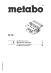
1
SETUP & OPERATION MANUAL
FEATURES
14” WOOD CUTTING BANDSAW
Cast-iron frame & precision-balanced aluminum wheels with replaceable rubber
tires.
Sturdy, easy to assemble, closed base steel
stand.
Precision aluminum miter gauge with handle.
2 cutting speeds for excellent results in
either hard or soft woods.
Hinged door and easily accessible blade
tension knob, for fast blade changes or
adjustments.
Ball-bearing and carbon block blade
guide assembly.
Built-in blade cleaning brush keeps tires
free of dust and chips.
Safety lock-out switch with removable key
to prevent unauthorized use.
SPECIFICATIONS
WHEEL SIZE
13 7⁄8 ” (353 mm)
WHEEL SPEEDS (2)
470/820 RPM
MAXIMUM BLADE WIDTH
3⁄4” (19 mm)
MINIMUM BLADE WIDTH
1⁄4” (6 mm)
BLADE LENGTH
93 1⁄2” (2375 mm)
BLADE SPEEDS (2)
1630 & 2730 LIN. FPM (495/832 LIN. MPM)
TABLE SIZE
16” x 16” (406 x 406 mm)
TABLE TILT
0°- 45° (RIGHT) / 0°-10° (LEFT)
TABLE HEIGHT
42” (1067 mm)
MAXIMUM WIDTH OF CUT
13 1⁄2” (343 mm)
MAXIMUM DEPTH OF CUT
6” (150 mm)
DUST COLLECTION PORT
2 1⁄2” (63 mm)
BASE DIMENSIONS (L x W)
19 5⁄8” x 13” (498 x 330 mm)
MODEL
#90-140 M1
MOTOR
1 HP, 110 V, 1 PH, 10 A
WEIGHT
191 LBS (87 kg)
REVISION 1 - March 10/10
© Copyright General® International 03/2010
GENERAL® INTERNATIONAL
8360 Champ-d’Eau, Montreal (Quebec) Canada H1P 1Y3
Telephone (514) 326-1161 • Fax (514) 326-5555 • www.general.ca
THANK YOU
for choosing this General® International model 90-140 M1 14”
Wood Cutting Bandsaw. This bandsaw has been carefully tested and inspected before shipment and if properly used and maintained, will provide you with years of reliable service. For
your safety, as well as to ensure optimum performance and trouble-free operation, and to get
the most from your investment, please take the time to read this manual before assembling,
installing and operating the unit.
The manual’s purpose is to familiarize you with the safe operation, basic function, and features
of this bandsaw as well as the set-up, maintenance and identification of its parts and components. This manual is not intended as a substitute for formal woodworking instruction, nor to
offer the user instruction in the craft of woodworking. If you are not sure about the safety of
performing a certain operation or procedure, do not proceed until you can confirm, from
knowledgeable and qualified sources, that it is safe to do so.
Once you’ve read through these instructions, keep this manual handy for future reference.
Disclaimer: The information and specifications in this
manual pertain to the unit as it was supplied from the
factory at the time of printing. Because we are committed to making constant improvements, General®
International reserves the right to make changes to
components, parts or features of this unit as deemed
necessary, without prior notice and without obligation to
install any such changes on previously delivered units.
Reasonable care is taken at the factory to ensure that
the specifications and information in this manual corres-
ponds with that of the unit with which it was supplied.
However, special orders and “after factory” modifications may render some or all information in this manual
inapplicable to your machine. Further, as several generations of this model of bandsaw and several versions of
this manual may be in circulation, if you own an earlier
or later version of this unit, this manual may not depict
your machine exactly. If you have any doubts or questions contact your retailer or our support line with the
model and serial number of your unit for clarification.
GENERAL® & GENERAL® INTERNATIONAL WARRANTY
All component parts of General®, General® International and Excalibur by General
International ® products are carefully inspected during all stages of production and each unit
is thoroughly inspected upon completion of assembly.
Limited Lifetime Warranty
Because of our commitment to quality and customer satisfaction, General® and General®
International agree to repair or replace any part or component which upon examination,
proves to be defective in either workmanship or material to the original purchaser for the life
of the tool. However, the Limited Lifetime Warranty does not cover any product used for professional or commercial production purposes nor for industrial or educational applications. Such
cases are covered by our Standard 2-year Limited Warranty only. The Limited Lifetime Warranty
is also subject to the “Conditions and Exceptions” as listed below.
Standard 2-Year Limited Warranty
All products not covered by our lifetime warranty including products used in commercial,
industrial and educational applications are warranted for a period of 2 years (24 months) from
the date of purchase. General® and General® International agree to repair or replace any
part or component which upon examination, proves to be defective in either workmanship or
material to the original purchaser during this 2-year warranty period, subject to the “conditions
and exceptions” as listed below.
To file a Claim
To file a claim under our Standard 2-year Limited Warranty or under our Limited Lifetime
Warranty, all defective parts, components or machinery must be returned freight or postage
prepaid to General® International, or to a nearby distributor, repair center or other location
designated by General® International. For further details call our service department at 1-888949-1161 or your local distributor for assistance when filing your claim.
Along with the return of the product being claimed for warranty, a copy of the original proof
of purchase and a “letter of claim” must be included (a warranty claim form can also be used
and can be obtained, upon request, from General® International or an authorized distributor)
clearly stating the model and serial number of the unit (if applicable) and including an explanation of the complaint or presumed defect in material or workmanship.
CONDITIONS AND EXCEPTIONS:
This coverage is extended to the original purchaser only. Prior warranty registration is not
required but documented proof of purchase i.e. a copy of original sales invoice or receipt
showing the date and location of the purchase as well as the purchase price paid, must be
provided at the time of claim.
Warranty does not include failures, breakage or defects deemed after inspection by General®
or General® International to have been directly or indirectly caused by or resulting from;
improper use, or lack of or improper maintenance, misuse or abuse, negligence, accidents,
damage in handling or transport, or normal wear and tear of any generally considered consumable parts or components.
Repairs made without the written consent of General® Internationallwill void all warranty.
TABLE OF CONTENTS
Rules for safe operation . . . . . . . . . . . . . . .5
Blade clearance . . . . . . . . . . . . . . . . . . . . . . . . . . .15
To remove a blade . . . . . . . . . . . . . . . . . . . . . . . . .15
Electrical requirements . . . . . . . . . . . . . . .6
Grounding instructions . . . . . . . . . . . . . . . . . . . . . . .6
Circuit capacity . . . . . . . . . . . . . . . . . . . . . . . . . . . . .6
Extension cords . . . . . . . . . . . . . . . . . . . . . . . . . . . . .6
Identification of main parts and
components . . . . . . . . . . . . . . . . . . . . . . . . . . . . . . . . . . . .7
Unpacking
. . . . . . . . . . . . . . . . . . . . . . . .8
Blade selection . . . . . . . . . . . . . . . . . . . . . . . . . . . .16
To install a blade . . . . . . . . . . . . . . . . . . . . . . . . . . .16
Adjusting blade tension . . . . . . . . . . . . . . . . . . . . .17
Adjusting blade tracking . . . . . . . . . . . . . . . . . . . .18
Adjusting the blade guard for depth of cut . . . .19
Adjusting the upper guide blocks and
thrust bearing . . . . . . . . . . . . . . . . . . . . . . . . . . . . . .19
List of contents . . . . . . . . . . . . . . . . . . . . . . . . . . . . . .8
Positioning the lower guide blocks and
thrust bearing . . . . . . . . . . . . . . . . . . . . . . . . . . . . . .20
Additional requirements for set up . . . . . . . . . . . . .8
Changing speed settings . . . . . . . . . . . . . . . . . . . .21
Basic functions of the unit . . . . . . . . . . . . .9
Operating instructions . . . . . . . . . . . . . . .21
Placement within the shop / Establishing a
safety zone . . . . . . . . . . . . . . . . . . . . . . . . . . . . . . . . . . . . .9
Checklist before starting . . . . . . . . . . . . . . . . . . . . .21
Connecting to a dust collector . . . . . . . . . . . . . . .22
Placement within the shop . . . . . . . . . . . . . . . . . . .9
Operations step-by-step . . . . . . . . . . . . . . . . . . . . .22
Establishing a safety zone . . . . . . . . . . . . . . . . . . . .9
To stop the machine . . . . . . . . . . . . . . . . . . . . . . . .22
Clean up . . . . . . . . . . . . . . . . . . . . . . . . . .9
Using the miter gauge . . . . . . . . . . . . . . . . . . . . . .22
Cutting curves . . . . . . . . . . . . . . . . . . . . . . . . . . . . .23
Assembly instructions . . . . . . . . . . . . . . .10
Cutting circles . . . . . . . . . . . . . . . . . . . . . . . . . . . . .23
Assemble the base cabinet . . . . . . . . . . . . . . . . . .10
Periodic Maintenance & Lubrication . . . . . .23
Install the bandsaw onto the base cabinet . . . .11
Attaching the dust port . . . . . . . . . . . . . . . . . . . . . .11
Lubrification . . . . . . . . . . . . . . . . . . . . . . . . . . . . . . .23
Periodic maintenance . . . . . . . . . . . . . . . . . . . . . .23
Attaching the table-tilt bracket . . . . . . . . . . . . . . .11
Attaching the table . . . . . . . . . . . . . . . . . . . . . . . . .12
Required Maintenance . . . . . . . . . . . . . . .24
Miter gauge . . . . . . . . . . . . . . . . . . . . . . . . . . . . . . .13
Replacing the bandsaw blade . . . . . . . . . . . . . . .24
Power cord hooks . . . . . . . . . . . . . . . . . . . . . . . . . .13
Replacing the upper and lower thrust bearing .24
Basic adjustments and controls . . . . . . . .13
Connecting to a power source . . . . . . . . . . . . . . .13
Replacing the wheel tire . . . . . . . . . . . . . . . . . . . .25
Adjusting/replacing the lower wheel brush . . . .25
Replacing lower wheel motor belt . . . . . . . . . . . .25
Power on/off switch with safety key . . . . . . . . . . . .13
Recommended adjustments . . . . . . . . . . .14
Adjusting the 90º table stop and re-aligning
the angle pointer . . . . . . . . . . . . . . . . . . . . . . . . . . . . . . . .14
Tilting the table . . . . . . . . . . . . . . . . . . . . . . . . . . . . .14
Removing/installing the blade . . . . . . . . . . . . . . .15
Recommended optional accessoriess . . . .26
Parts list & diagrams . . . . . . . . . . . . . .27-33
Rules for Safe Operation
To help ensure safe operation, please take a moment to learn the machine’s applications and limitations, as well as potential hazards. General® International disclaims any real or implied warranty and
hold itself harmless for any injury that may result from the improper use of it’s equipment.
1. Do not operate the bandsaw when tired, distracted
or under the effects of drugs, alcohol or any medication that impairs reflexes or alertness.
15. Use suitable workpiece support if the workpiece
does not have a flat surface.
16. Hold material firmly against the table.
2. The working area should be well lit, clean and free
of debris.
3. Keep children and visitors at a safe distance when
the bandsaw is in operation; do not permit them to
operate the bandsaw.
4. Childproof and tamper proof your shop and all
machinery with locks, master electrical switches
and switch keys, to prevent unauthorized or unsupervised use.
5. Stay alert! Give your work your undivided attention.
Even a momentary distraction can lead to serious
injury.
6. Fine particulate dust is a carcinogen that can be
hazardous to health. Work in a well-ventilated area
and whenever possible use a dust collector. Wear
face, eye, ear, respiratory and body protection devices.
17. Do not work on long stock without adequate support on the out feed end of the table.
18. If using a power feeder, stop the feeder before stopping the bandsaw.
19. Do not push or force stock into the blade. The bandsaw will perform better and more safely when working at the rate for which it was designed.
20. Avoid working from awkward or off balance positions. Do not overreach and keep both feet on floor.
21. Keep guards in place and in working order. If a
guard must be removed for maintenance or cleaning be sure it is properly re-attached before using
the tool again.
22. Never leave the machine unattended while it is running or with the power on.
7. Do not wear loose clothing, gloves, bracelets,
necklaces or other jewelry while the bandsaw is in
operation.
23. Use of parts and accessories NOT recommended
by General® International may result in equipment malfunction or risk of injury.
8. Be sure that adjusting wrenches, tools, drinks and
other clutter are removed from the machine and/or
the table surface before operating.
24. Never stand on machinery. Serious injury could result if the tool is tipped over or if the cutting tool is
unintentionally contacted.
9. Keep hands well away from the blade and all moving parts. Use a brush, not hands, to clear
away chips and dust.
25. Always disconnect the machine from the power
source before servicing or changing accessories
such as blades, or before performing any maintenance or cleaning, or if the machine will be left unattended.
10. Adjust and position upper and lower blade guides
before starting to cut. Upper blade guide should be
adjusted to approximately 1/8” above the material
to be cut.
11. Adjust blade tension and tracking before starting to
cut.
26. Make sure that the switch is in the “OFF” position before plugging in the power cord.
27. Make sure the tool is properly grounded. If equipped with a 3-prong plug it should be used with a
three-pole receptacle. Never remove the third prong.
12. Saw teeth must point down toward the table.
13. Be sure that the blade has gained full operating
speed before starting to cut.
14. Always use a clean, properly sharpened blade.
Dirty or dull blades are unsafe and can lead to
accidents.
28. Do not use this bandsaw for other than its intended
use. If used for other purposes, General® International disclaims any real implied warranty and holds
itself harmless for any injury, which may result from
that use.
5
ELECTRICAL REQUIREMENTS
BEFORE CONNECTING THE MACHINE TO THE POWER SOURCE, VERIFY THAT THE VOLTAGE OF YOUR POWER SUPPLY CORRESPONDS
WITH THE VOLTAGE SPECIFIED ON THE MOTOR I.D. NAMEPLATE. A POWER SOURCE WITH GREATER VOLTAGE THAN NEEDED CAN
RESULT IN SERIOUS INJURY TO THE USER AS WELL AS DAMAGE TO THE MACHINE. IF IN DOUBT, CONTACT A QUALIFIED ELECTRICIAN
BEFORE CONNECTING TO THE POWER SOURCE.
THIS TOOL IS FOR INDOOR USE ONLY. DO NOT EXPOSE TO RAIN OR USE IN WET OR DAMP LOCATIONS.
EXTENSION CORDS
If you find it necessary to use an extension cord with your
machine, use only 3-wire extension cords that have 3prong grounding plug and a matching 3-pole receptacle that accepts the tool’s plug. Repair or replace a
damaged extension cord or plug immediately.
A
B
C
GROUNDING INSTRUCTIONS
In the event of an electrical malfunction or short circuit,
grounding reduces the risk of electric shock. The motor
of this machine is wired for 110V single phase operation
and is equipped with a 3-conductor cord and a 3prong grounding plug A to fit a grounded type receptacle B. Do not remove the 3rd prong (grounding pin) to
make it fit into an old 2-hole wall socket or extension
cord. If an adaptor plug is used C, it must be attached
to the metal screw of the receptacle.
Note: The use of an adaptor plug is illegal in some
areas. Check your local codes. If you have any doubts
or if the supplied plug does not correspond to your electrical outlet, consult a qualified eletrician before proceeding.
CIRCUIT CAPACITY
Make sure that the wires in your circuit are capable of
handling the amperage draw from your machine, as
well as any other machines that could be operating on
the same circuit. If you are unsure, consult a qualified
electrician. If the circuit breaker trips or the fuse blows
regularly, your machine may be operating on a circuit
that is close to its amperage draw capacity. However, if
an unusual amperage draw does not exist and a
power failure still occurs, contact a qualified technician
or our service department.
6
Make sure the cord rating is suitable for the amperage
listed on the motor I.D. plate. An undersized cord will
cause a drop in line voltage resulting in loss of power
and overheating. The accompanying chart shows the
correct size extension cord to be used based on cord
length and motor I.D. plate amp rating. If in doubt, use
the next heavier gauge. The smaller the number, the
heavier the gauge.
EXTENSION CORD LENGTH
AMPERES
(AMPS)
25 FEET
50 FEET
100 FEET
150 FEET
<5
18
16
16
14
6 TO 10
18
16
14
12
10 TO 12
16
16
14
14
12 TO 16
14
12
* NR
* NR
* NR = Not Recommended
IDENTIFICATION OF MAIN PARTS AND COMPONENTS
FRONT VIEW
BLADE TENSION ADJUSTMENT KNOB
BLADE GUARD LOCK KNOB
UPPER BLADE GUIDE ASSEMBLY
BLADE GUARD
MITER GAUGE
TABLE ALIGNMENT PIN
DUST PORT
BASE CABINET
TABLE TILT LOCK KNOB
LOWER WHEEL COVER DOOR
ON/OFF SWITCH W/SAFETY KEY
UPPER WHEEL COVER DOOR
REAR VIEW
BLADE TRACKING ADJUSTMENT KNOB
BLADE TENSION INDICATOR
POWER CORD STORAGE BRACKETS
MOTOR PIVOT LOCKING LEVER
7
UNPACKING
Carefully unpack and remove the unit and its components from its shipping container and check for missing or
damaged items as per the list of contents below.
NOTE: Please report any damaged or missing items to your GENERAL® INTERNATIONAL distributor immediately.
LIST OF CONTENTS
Once the parts have been removed from the packaging, you should have the following items:
QTY
A- BANDSAW . . . . . . . . . . . . . . . . . . . . . . . . . . . . . . . . . . .1
B- POWER CORD HOOK W/SCREW . . . . . . . . . . . . . . . .2
C- DUST PORT . . . . . . . . . . . . . . . . . . . . . . . . . . . . . . . . . . . . .1
D- HEX HEAD BOLT . . . . . . . . . . . . . . . . . . . . . . . . . . . . . .4
E- FLAT WASHER . . . . . . . . . . . . . . . . . . . . . . . . . . . . . . . .8
F- HEX NUT . . . . . . . . . . . . . . . . . . . . . . . . . . . . . . . . . . . .4
G- LOCK KNOB . . . . . . . . . . . . . . . . . . . . . . . . . . . . . . . . .2
H- MEDIUM HEX HEAD HEAD BOLT W/FLAT WASHER . . .2
I- LONG HEX HEAD BOLT W/HEX NUT . . . . . . . . . . . . . .1
J- MITER GAUGE . . . . . . . . . . . . . . . . . . . . . . . . . . . . . . .1
K- TABLE TILT BRACKET . . . . . . . . . . . . . . . . . . . . . . . . . . .1
L- TABLE . . . . . . . . . . . . . . . . . . . . . . . . . . . . . . . . . . . . . .1
M- 3 MM ALLEN KEY . . . . . . . . . . . . . . . . . . . . . . . . . . . . .1
N- CARRIAGE BOLT . . . . . . . . . . . . . . . . . . . . . . . . . . . . .16
O- FLANGE NUT . . . . . . . . . . . . . . . . . . . . . . . . . . . . . . . .16
P- PHILLIPS HEAD SCREW . . . . . . . . . . . . . . . . . . . . . . . . .8
Q- LEVELING FOOT . . . . . . . . . . . . . . . . . . . . . . . . . . . . . .4
R- HEX NUT . . . . . . . . . . . . . . . . . . . . . . . . . . . . . . . . . . . .4
S- DOOR KNOB W/HEX BOLT AND FLAT WASHER . . . . .1
T- STAND TOP PLATE . . . . . . . . . . . . . . . . . . . . . . . . . . . . .1
U- STAND TOOL TRAY . . . . . . . . . . . . . . . . . . . . . . . . . . . .1
V- STAND DOOR . . . . . . . . . . . . . . . . . . . . . . . . . . . . . . . .1
W- STAND REAR PANEL . . . . . . . . . . . . . . . . . . . . . . . . . . .1
X- STAND LEFT SIDE PANEL . . . . . . . . . . . . . . . . . . . . . . . .1
Y- STAND RIGHT SIDE PANEL . . . . . . . . . . . . . . . . . . . . . .1
B
A
C
D
E
F
G
H
I
J
K
K
M
ADDITIONAL REQUIREMENTS FOR SET UP
STAND ASSEMBLY
•
•
•
•
•
•
•
•
•
Extra person for help with lifting
Phillips screwdriver (regular and small)
Flat head screwdriver
10 mm wrench and 10 mm Hex socket
12 mm wrench and 12 mm Hex socket
13mm wrench and 13 mm Hex socket
14 mm wrench and 14 mm Hex socket
Feeler gauge set
Combination square
N
O
S
P
T
Q
W
R
U
8
X
V
Y
BASIC FUNCTIONS OF THE UNIT
This 14" wood cutting bandsaw is supplied with a 3/8" wide
general purpose blade and is designed to accommodate
blade widths from 1/4" to 3/4". Ideal blade length for this 90140 M1 model is 93 1/2" (2375 mm).
Note: Generally speaking, because the upper wheel height is
somewhat adjustable (to allow for blade tensioning), a blade
length variation of plus or minus 1/2" from the “ideal blade
length” can be accommodated.
A
Maximum inboard width of cut (space between the blade
and the body of the saw A) is 13 1/2".
B
For cutting thicker stock or for resawing, the maximum
depth of cut B (or max. workpiece height) is 6" (up to 12"
with optional “riser block kit” item #90-130A – Refer to section
“Recommended Optional Accessories for your Bandsaw”.
PLACEMENT WITHIN THE SHOP / ESTABLISHING A SAFETY ZONE
THIS MODEL 90-140 M1 BANDSAW IS HEAVY (191 LBS - 87 KG). DO NOT OVER-EXERT. THE HELP OF AN ASSISTANT
WILL BE NEEDED FOR THE FOLLOWING STEP.
PLACEMENT WITHIN THE SHOP
This machine should be installed and operated only on a
solid, flat and stable floor that is able to support the weight
of the bandsaw 191 LBS (87 kg) and the operator. Using the
dimensions shown as a guideline, plan for placement within your shop that will allow the operator to work unencumbered and unobstructed by foot traffic (either passing shop
visitors or other shop workers) or other tools or machinery.
66”
16”
ESTABLISHING A SAFETY ZONE
For shops with frequent visitors or multiple operators, it is
advisable to establish a Safety Zone around shop machinery. A clearly defined “no-go” zone on the floor around
each machine can help avoid accidents that could cause
injury to either the operator or the shop visitor. It is advisable
to take a few moments to either paint (using non-slip paint)
or using tape, define on the floor the limits or perimeter of each machines safety zone. Take steps to ensure that all
operators and shop visitors are aware that these areas are off limits whenever a machine is running for everyone
but the individual operating the unit.
27”
CLEAN UP
The protective coating on the saw table prevents rust
from forming during shipping and storage. Remove it by
rubbing with a rag dipped in kerosene, mineral sprits or
paint thinner. (Dispose of potentially flammable solventsoaked rags according to manufacturer’s safety recommendations.)
A putty knife, held flat to avoid scratching the surface,
may also be used to scrape off the coating followed by
clean-up with solvent. Avoid rubbing the saw’s painted
surfaces, as many solvent-based products will remove
paint.
To prevent rust, apply a light coating of paste wax or use
regular applications of any after-market surface protectant or rust inhibitor.
Tip: With a screw driver, push a solvent-saturated rag into
the T-slot to remove the grease so the miter gauge will
slide freely.
9
ASSEMBLY INSTRUCTIONS
SERIOUS PERSONAL INJURY COULD OCCUR IF YOU CONNECT THE MACHINE TO THE POWER SOURCE BEFORE YOU
HAVE COMPLETED THE INSTALLATION AND ASSEMBLY STEPS. DO NOT CONNECT THE MACHINE TO THE POWER
SOURCE UNTIL INSTRUCTED TO DO SO.
ASSEMBLE THE BASE CABINET
A
B
C
1. Thread a leveling foot A with a hex nut B on both
side panels as shown above.
D
2. Attach the left and right side panels to the tool tray
using 8 carriage bolts C and flange nuts D, then
tighten using a 12 mm open wrench.
F
E
3. Attach the top plate to the left and right side panels using 4 carriage bolts C and flange nuts D as
shown above.
4. Attach the rear panel to the top plate and tool tray
using 4 Phillips head screws F as shown above.
Note: The flanges of the top plate should fit inside the cabinet E.
K
G
H
I
5. Attach the door knob G to the door using the supplied hex head bolt H and lock washer I as shown
above.
10
J
6. Attach the door to the hinges on the right side panel as shown using 4 Phillips head screws J.
Note: Hinges go behind side panel edge K.
INSTALL THE BANDSAW ONTO THE BASE CABINET
The bandsaw mounts onto a base cabinet which provides
storage space for the miter gauge and replacementblades.
Important! Make sure all stand fasteners are firmly tightened
and that the stand cabinet is installed on a solid, flat and stable floor that is able to support the weight of the bandsaw 191
LBS (87 kg)
A
B
C
The bandsaw is heavy. Do not over-exert. The help of
an assistant will be needed for the following step.
Do not grip the bandsaw by the lower wheel cover
door when lifting. Keep hands away from blade at all
times.
1.
Position the bandsaw over the four holes on top of the
base cabinet.
2.
Using a 13 mm open end wrench and a 13 mm socket wrench, secure the bandsaw to the stand as
shown using the 4 hex head bolts A, 8 flat washers B
and 4 hex nuts C.
Note: The hex nuts must be tightened from inside the cabinet.
ATTACHING THE DUST PORT
A
The dust port A has a 2 –1/2" opening to accommodate
connection to a dust collector (not included). Install the
dust outlet on the right side of the bandsaw as follows:
1.
Open the lower wheel cover door.
2.
Using a 10 mm wrench, attach the dust port to the
edge of the door as shown using the hex bolts and
washers B already attached to the dust port.
ATTACHING THE TABLE-TILT BRACKET
B
LOWER WHEEL HOUSING
The work table mounts on a bracket which allows adjustment from flat (0°) to any angle up to 45° to the right.
Adjustments can be made easily with the angle scale and
lock knobs.
1.
Remove the two hex bolts and washers from the lower
wheel housing A.
2.
Place the table-tilt bracket B on the lower wheel housing as shown in C and align holes to the threaded
holes in the lower wheel housing (hole D is not used).
3.
Place washers on the two hex bolts E and F and insert the bolts through the table-tilt bracket holes and
into the threaded holes in the lower wheel housing.
4.
Tighten loosely, using a 12 mm open end wrench
and 12 mm socket wrench.
5.
Thread a nut onto the longer table-stop bolt D and
screw the bolt into the hole on the rear tab of the table
tilt bracket.
A
NOT USED
E
F
D
D
F
B
E
C
* Final tightening will be done after centering the table
opening with the blade.
11
ATTACHING THE TABLE
A
B
C
1.
Remove the red insert A from the center of the
table and the table alignment pin B from the table
slot.
D
2.
C
Turn the table right side up. Verify that the long
bolts C in the center of each trunnion are pointing
down the holes in the table-tilt bracket.
E
C
F
3.
Carefully move the table into position over the
table-tilt bracket, guiding the saw blade through
the table slot D.
5.
4.
Rotate the table 1/4 turn counter-clockwise so that
the saw blade is now perpendicular to the table
slot E.
Note: If the long bolts have moved out of position, have an
assistant tap them into place with a screw driver.
6.
K
Gently lower the table onto the bracket so the
long bolts C in the center of the trunnions pass
through the holes in the table-tilt bracket.
Thread the two lock knobs F onto the long bolts
now protruding from the underside of the tabletilt bracket and tighten loosely.
L
G
F
H
H
I
J
7.
12
Make sure that the blade F is centered in the table
opening G. If the blade is not centered, slide the
table back or forward until the blade is centered
in the table opening. Then tighten the six combination head bolts H using a 10 mm wrench and
the two hex bolts I and J using a 12 mm open
wrench and 12 mm socket wrench.
8.
Re-install the red insert to the center of the table,
with the opening in the slot facing the rear of the
saw K.
9.
Re-install the table alignment pin into the table
slot L.
POWER CORD HOOKS
MITER GAUGE
E
C
A
G
B
F
The miter gauge rides in the table slot to the right of the
blade A and can be set to any angle up to 30° to the
left or right B.
It also acts as a feeder for advancing smaller workpieces through the sawblade C with reduced risk of
injury to the hands.
When the bandsaw is not in use, we recommend that
the power cord be wound up neatly around the two
hooks E provided . This keeps the power cord off of the
floor and out of harms way.
Attach the hooks with the two Phillips head bolts F to
the threaded holes on the back of the upper arm of
the bandsaw G.
BASIC ADJUSTMENTS AND CONTROLS
CONNECTING TO A POWER SOURCE
To avoid risk of shock or fire do not operate the unit with a damaged power cord or plug. Replace damaged
cord or plug immediately.
To avoid unexpected or unintentional start-up,
make sure that the power switch is in the the
OFF position before connecting to a power
source.
1.
SWITCH «OFF»
Uncoil the power cord A and plug it into an appropriate outlet (refer back to section “Electrical Requirements" and make sure all requirements and
grounding instructions are followed).
POWER ON/OFF SWITCH WITH SAFETY KEY
The model 90-140 ‘M is equipped with a simple “rocker
style” On/Off switch featuring a removable lock out
safety key D to prevent unauthorized use or unintentional start-up of the bandsaw. Whenever the bandsaw is
not in use, remove the yellow safety key and store it in
a safe place, out of the reach of children.
-
To START the bandsaw: Insert the safety key D and pull
the switch toward you E.
-
To STOP the bandsaw: Push the red tab down F.
E
D
SAFETY KEY *
ON
F
OFF
* PREVENTS START-UP WHEN REMOVED
13
RECOMMENDED ADJUSTMENTS
ADJUSTING THE 90º TABLE STOP AND RE-ALIGNING THE ANGLE POINTER
To ensure that your 90º cuts are square and that angled cuts are accurate with the angle indicator scale, the table
default position must be set to 90º to the blade and the angle indicator pointer must be set to read 0 when the table
is in the default (90º) position. To set the table-stop bolt:
C
B
A
1.
Loosen the two lock knobs A.
2.
Place a combination square B flat on the table
with the heel of the square flat against the saw
blade C.
3.
Level the table until it is exactly 90° to the blade,
then tighten the lock knobs A.
E
D
E
G
F
F
H
H
I
4.
Adjust the height of the table-stop bolt until it touches the underside of the table D.
5.
Turn the jam-nut E clockwise until it meets the
table tilt-bracket F and tighten it.
6.
Loosen the lock knobs G and make sure the table
is resting on the table-stop bolt D.
7.
Check the square and make sure the table is still at
90° to the blade. If not, re-adjust the table-stop bolt.
8.
With the table set to 90º and the stop bolt at the
correct height, make sure the table tilt angle indicator pointer H is set to read 0º.
9.
If the pointer needs to be adjusted, loosen the
screw I on the pointer of the front trunnion and
adjust the pointer H to the 0 point on the scale.
Then re-tighten the screw to secure the pointer in
place.
You will now be able to accurately return the table to the 90º position automatically without further adjustments and
scale reading for any angle other than 0 will also be accurate.
TILTING THE TABLE
The table can be tilted to any angle from 0° to 45° to the right, to allow for any type of bevel (or angle) cutting. Refer
to the table tilt angle indicator to set the angle of the table to the desired position.
Never adjust the table angle while the bandsaw is running. Turn off power first.
1.
Loosen the two lock knobs A.
2.
Tilt the table until it is at the desired angle. (Refer to
the angle indicator under the bandsaw table.)
3.
Tighten the lock knobs to lock the table in position.
14
A
REMOVING / INSTALLING THE BLADE
Your bandsaw is designed to handle several blade widths ranging from 1/4” and 3/8” used for tight radius curves,
up to 1/2” and 3/4” for larger radius curves or for cutting thicker stock.
BLADE CLEARANCE
Note: When performing blade installation, removal, tensioning or tracking, maximum clearance between the blade
and both upper and lower blade guide assemblies is required to minimize friction, which would be damaging to the
blade.
Proceed as follows:
D
Move the upper guide blocks away from the blade:
1. Loosen the two set screws A using the supplied 3 mm
Allen key.
C
C
2. Pull back the 2 upper guide blocks B in their mounting
bracket C, as far away as possible from the blade.
B
3. Tighten the two set screws A to lock the guide blocks in
position.
B
A
A
Move the upper thrust bearing back:
1.
Loosen the upper thumb screw D.
2.
Use the micro adjust nut E to move the thrust bearing F
back as far as possible behind the blade.
Move the lower guide blocks / thrust bearing away from the blade:
F
E
1.
Loosen the two set screws G using the supplied 3 mm
Allen key.
2.
Pull back the 2 lower guide blocks H in their mounting
bracket I, as far away as possible from the blade.
3.
Tighten the two set screws G to lock the guide blocks in
position.
4.
Loosen the upper set screw J using the supplied 3 mm
Allen key.
5.
Manually move the lower thrust bearing K back as far
as possible behind the blade.
K
J
I
H
G
G
To remove a blade:
B
D
A
C
1.
Turn off the bandsaw and unplug the power cord.
2.
Turn the tension knob A counter-clockwise for
the blade to be loose enough to remove easily.
E
3.
Remove the table alignment pin from the table
slot B and the red circular insert C from the center of the table.
4.
Remove the right hand side blade guard D by
loosening the two Phillips head screws E just
enough to slide it out
15
Blade teeth are sharp.
Use care when handling a saw blade.
5.
G
F
Open the top and bottom wheel cover doors and
bring the left hand side of the loose blade toward
you and out of the left hand blade guard slot F.
Note: You may want to use a thick shop towel to handle the
loose blade or wear a pair of heavy duty work gloves.
6.
With the blade perpendicular to the wheels, feed
the blade through the table slot to free it from the
saw G.
7.
Carefully hang the blade on a hook in a safe, dry place in your workshop if it will be re-used, or dispose of it
safely if it is worn or damaged.
Do not attempt to coil up the blade as it was when you first purchased it as it has a tendancy to pop open
unexpectedly and could cause injury.
BLADE SELECTION
There are a variety of different types of bandsaw blades on the market to suit various cutting applications. Your results
may vary based on usage, experience and personal preference.
Standard size - 93 1⁄2” (2375 mm) - replacement blades made from high carbon steel can be purchased in a variety
of widths from your General® International dealer under the following parts numbers:
• #90125-B14:1/4” - 6 TPI, blade thickness: 0.65 mm
• #90125-B12: 1/2” - 4 TPI, blade thickness: 0.65 mm
• #90125-B38: 3/8” - 6 TPI, blade thickness: 0.50 mm
• #90125-B34: 3/4” - 4 TPI, blade thickness: 0.65 mm
or (depending on availability) from your local tool dealer. These are standard sizes that should be readily available
in most areas. The use of any other size is not recommended and can lead to serious injury and/or damage to the
machine.
Some general guidelines to consider when choosing bandsaw blades:
• Wider blades with fewer teeth per inch are best suited to cutting straight lines, re-sawing and for sweeping curves,
but will not turn tight radius curves. They will cut quickly and aggressively but do have a tendency to bind (or get
stuck in the cut) if turned too sharply.
•Narrower, thinner blades with more teeth per inch will cut more slowly but can turn much tighter corners for cutting
more intricate work.
Common causes of blade breakage:
• Poor guide bearing alignment and adjustment.
• Forcing or twisting a wide blade around a short radius.
• Setting blade guard assembly too high above the workpiece.
• Lumpy or improperly finished braze or weld on the blade.
To install a blade:
1.
Turn off the bandsaw and unplug the power cord.
Beware of the blade popping open.
2.
16
If you are installing a new blade, carefully remove the
blade from its package. Hold it firmly with one hand as
you remove the twist ties. Slowly separate the coils of
the blade until it unravels into one hoop.
• Feeding the workpiece too quickly.
• Dull teeth.
• Too much blade tension.
• Continuous running of blade when not cutting.
Note: You may want to use a thick shop towel to
handle the loose blade or wear a pair of heavy
duty work gloves for the following steps.
Note: Steps 3 and 4 may be unnecessary if you’ve just removed a blade. (If needed, refer back to the previous page.)
3.
Remove the table alignment pin from the table slot and the red circular insert from the center of the table.
4.
Remove the right hand side blade guard by loosening the two Phillips head screws, just enough to slide it out.
5.
With the blade perpendicular to the wheels, guide it
through the table slot, then rotate the side of the blade
nearest you back toward the left side of the wheels.
6.
Feed the blade into the left blade guard and around the
wheels. Make sure the blade teeth point forward A and
down B.
Proper installation
Improper installation
B
A
With the blade properly installed, proceed to blade tension
adjustments and blade tracking adjustments, as per instructions on the next few pages.
ADJUSTING BLADE TENSION
Determining ideal blade tension is somewhat subjective. It is learned through practice and experience and is somewhat dependant on personal preference and individual work habits.
A properly tensioned blade is critical to obtaining maximum performance from any bandsaw. A properly tensioned
blade will last longer and be much less likely to break prematurely. If the blade tension is too loose you will notice
that the blade will have a tendency to drift or slip off-line when cutting and you will have more difficulty controlling
your cuts. A blade that is tensioned too tightly will break prematurely and will be difficult to work with when making
tighter radius cuts.
The following information can be used as a guideline or starting point to assist you in determining ideal blade tension for your needs:
•
When working with wider blades, re-sawing taller stock, making straight cuts or wide sweeping curves tighter blade tensions will provide better results.
•
When working with narrower blades, sawing shorter stock and making tighter curved cuts are best performed using less tension
This model 90-140 M1 bandsaw is equipped with a blade tension scale, which can be used as a reference for the
ideal setting with various blade widths.
B
C
A
1.
Refering to the blade tension scale A, set the
blade tension to correspond with the width of the
blade installed on your bandsaw. Adjust the
blade tensioning by turning the blade tension
knob B:
3.
With the saw turned off, press against the side of
the blade to test the tautness of the blade C. For
ideal results with most blade widths and cutting
applications the blade should flex in no more than
1/4" to 3/8".
a) Clockwise to tighten
4.
Make a test cut on a sample piece of wood and if
needed re-adjust the blade tension
b) Counter-clockwise to loosen the blade tension.
Note: To prolong the life of the blade whenever the bandsaw is not in use for prolonged periods (more than 24
hours), release the blade tension lever to remove tension from the blade, Over time, maintaining tension on a
blade that is not in use will cause the blade to deform, by taking the shape of the wheels at both extremities. This
can weaken the blade and cause premature breakage.
17
ADJUSTING BLADE TRACKING
B
3 mm - 1/8"
Blade tracking means centering the blade on the wheels A.
A
Ideally, the blade should stay relatively centered on both the
upper and lower wheels.
Due to natural variations in castings, blade thickness or density and tire wear, absolute perfect centering alignment is
rarely attainable. A slight misalignment of the blade on the
wheels is inevitable and as long as it is kept to a minimum
(following the steps listed below) will not hinder the performance of the saw.
This misalignment is controlled and kept to a minimum by adjusting the tilt angle of the upper wheel.
When adjusting blade tracking to center the blade on the wheels and assuming that perfect centering is not attainable, it is preferable to have the blade slightly off-center towards the front of the wheels rather than towards the rear
because the teeth on most bandsaw blades have alternating hook (one inner, one outer) – therefore if the blade is
centered too far back on the wheel (or if the blade tension is too tight), inner hooked teeth will dig into the wheel
tire and cause premature wear of the tire.
Nonetheless, to avoid having the blade come off of the wheels on it’s own during operation, the front edge of the
blades teeth should never be any closer than 3 mm (1/8”) from the front edge of the wheel B.
BLADE CLEARANCE
Note: As previously stated, when performing blade installation, removal, tensioning or tracking, maximum clearance
between the blade and both upper and lower bearing assemblies is required to minimize friction, which would be
damaging to the blade. Refer back and follow the instructions for “blade clearance” before performing blade tracking adjustments.
To adjust the blade tracking:
A
1.
Open the upper wheel cover door then rotate the wheel
slowly forward by hand. The blade should remain as centered as possible on the wheel as it turns A.
2.
If the blade tracking must be adjusted, loosen thumb
nut B, then turn the tracking knob C, located on the rear
of the bandsaw:
B
a) Clockwise if the blade moves toward the front of the
wheel. This tilts the top of the wheel to the back and moves the blade toward the center.
b) Counter-clockwise if the blade moves toward the back
edge. This tilts the top of the wheel to the front and moves the blade toward the center.
Note: Turn the tracking knob in 1/2 turn increments, recheck and adjust again as needed.
3.
18
Re-tighten thumb nut B
C
ADJUSTING THE BLADE GUARD FOR DEPTH OF CUT
The blade guard can be moved up or down to accommodate the height of the work to be cut. To prevent the
blade (which is flexible and which would not otherwise
be supported) from slipping out of position during cutting, and to reduce risks of injuries, a minimum amount
of blade should be exposed.
REAR VIEW
B
C
1/8” - 1/4”
The blade guard should be set 1/8” - 1/4” above the workpiece A to prevent the blade from flexing out of position or
off-line during cutting.
Adjust the height of the blade guard B to suit the thickness of the workpiece as follows:
A
1. Make sure the bandsaw is turned off and the power
cord is disconnected from the power source.
E
2. Loosen the smaller lock knob C.
3. Move the blade guide assembly up or down D, then
re-tighten the lock knob C.
D
Note: The depth gauge E on the front of the blade guard can
be used as a reference but it is not intended for high precision measurements.
ADJUSTING THE UPPER GUIDES BLOCKS AND THRUST BEARING
Note: Before adjusting the upper and lower blade guides and thrust bearings, make sure the blade is tensioned and tracking properly. Adjust the upper and lower blade guides and thrust bearings after each blade tension and tracking adjustment. Whenever the upper blade guide and thrust bearing are adjusted, the lower blade guide and thrust bearing should
also be adjusted.
The blade guides blocks keep the blade from moving from side to side during cutting and must be snug but not
touching the blade in order to ensure accurate cuts. The space between each block and the blade must not
exceed 0.02" (the thickness of a sheet of paper). If less space is left, the blade will get stuck or jammed between
both blocks. Too much friction will cause blade to overheat and break. Also, the guide blocks must remain at least
1/32” behind the blade teeth to prevent damage to the blade.
The thrust bearing keeps the blade from moving back and out of position when the work is being fed into the blade
and must be very close to the back of the blade to prevent damage to the blade during cutting.
Adjust the positioning of the upper blade guides blocks:
To avoid injury, make sure that the switch is in
the “OFF” position and that the power cord is
unplugged before performing any adjustments
on the bandsaw.
1. Loosen the two set screws A using the supplied 3 mm
Allen key.
2. Push the guide blocks B towards the blade.
A
B
A
19
H
E
D
C
G
F
3. Pinch a feeler gauge C between one of the guide
blocks and the blade D, and then tighten the set
screw E to set the gap between the guide block
and the blade.
4. Repeat step 3 for the other guide block on the
other side of the blade.
5. Loosen the lower thumb screw F.
6. Turn the micro lower adjust nut G to move the guide
block assembly in or out until the guide blocks are
at least 1/32” behind the blade teeth H. The guide
blocks must remain behind the blade teeth to prevent damage to the blade.
7. Tighten the thumb screw F to lock the guide block
assembly in position.
Adjust the positioning of the upper thrust bearing:
K
M
L
1/64"
J
1.
Loosen the upper thumb screw J.
2.
Turn the micro adjust nut K to move the thrust bearing L in or out until the bearing is 1/64” behind the
back edge of the blade M, then tighten the upper
thumb screw J.
POSITIONING THE LOWER GUIDE BLOCKS AND THRUST BEARING
The lower blade guide blocks and thrust bearing perform the same function as the upper blade guide blocks and
thrust bearing except they do so after the blade has contacted the stock being cut.
1.
Repeat steps 1 to 4 of section “Adjust the positioning of the upper blade guides blocks” with the lower blade
guide blocks.
2. Loosen the lower set screw A using the supplied 3
mm Allen key.
3. Manually move the guide block assembly in or out
B until the guide blocks are at least 1/32” behind
the blade teeth.
D
C
4. Tighten the lower set screw A to lock the guide
block assembly in position.
5. Loosen the upper set screw C.
6. Manually move the thrust bearing D in or out until
the bearing is 1/64” behind the back edge of the
blade, then tighten the upper set screw C.
20
B
A
CHANGING SPEED SETTINGS
This model 90-140 14" wood cutting bandsaw has 2 different speed settings; low and high.
-
Low speed is to be used for cutting soft woods over 4" in height or hard woods over 2" in height.
-
High speed is best for cutting soft woods under 4" in height or hard woods under 2" in height.
Note: If wood starts to burn at high speed, stop and change to the lower speed setting.
To change the speed setting:
1.
Turn off power and disconnect the bandsaw from the power source to avoid unintentional start-up of the bandsaw.
2.
Open the lower wheel cover door.
3.
At the back of the bandsaw, just above the motor, there is
a ratchet lever A for loosening the tension on the drive
belt. When you pull it out, as in A, it disengages for resetting.
When you release it as in B, it engages the bolt for screwing
or unscrewing. (You can tell when it is engaged by the
orange indicater button B showing).
A
B
B
C
A
To loosen the drive belt, unscrew the bolt a few turns counterclockwise then pull up on the capacitor cover of the motor C
pivot the motor to the left. This loosens the belt enough to move
it between one set of pulleys and the other.
4. To set the bandsaw speed to the slower setting; 1630 FPM
(495MPM), place the belt on the frontmost set of pulleys
as in D.
D
E
5. To set the bandsaw speed to the faster setting; 2730 FPM
(832MPM), place the belt on the rearmost set of pulleys
as in E.
6. Having repositioned the belt, push down firmly on the motor capacitor cover to tighten the belt, then turn the ratchet lever clockwise until it is tight and the motor does not
move.
OPERATING INSTRUCTIONS
CHECKLIST BEFORE STARTING
NOTE: Now that you have completed the four adjustment steps which are an essential part of safe, accurate bandsaw
operation, it would be a good idea to make yourself a checklist as follows to ensure that each adjustment to the bandsaw
is made in the proper order starting with the general safety precaution:
1.
Turn off the bandsaw and unplug the power cord.
2.
Adjust blade tension.
3.
Adjust blade tracking.
4.
Adjust upper blade guides and thrust bearing.
5.
Adjust lower blade guides and thrust bearing.
These additional safety measures should be be included in your checklist:
6.
Make sure all the blade guards are in place.
7.
Make sure the bandsaw table and work area in general are clean and free of sawdust and debris.
These steps should always be followed when any adjustment is performed, the blade is changed, or periodically as vibration and normal wear and tear on the machine could throw these parts out of alignment.
21
CONNECTING TO A DUST COLLECTOR
A dust port with a 2.5” opening is provided to accommodate
connection to a dust collector (not included).
Once the dust port has been installed (See Previous section
“Attaching the dust port”), be sure to use appropriate sized
hose and fittings (not included) and check that all connections are sealed tightly to help minimize airborne dust.
If you do not already own a dust collection system consider
contacting your General® International distributor for information on our complete line of dust collection systems and
accessories or visit our Web Site at: www.general.ca.
OPERATIONS STEP-BY-STEP
To reduce the risk of damage to the bandsaw or the workpiece, as well as a potential for personal injury, after initial set-up as well as before each use, make sure that everything is securely installed and that all fasteners and
moving parts on this bandsaw are locked in place before starting the machine.
1.
Trace the cutting line on your workpiece with a pencil.
2.
Set the height of the blade guard according to the thickness of your workpiece (see section: “Adjusting the blade guard for depth of cut” on page 19.)
3.
If a dust collector is connected to your bandsaw, turn it on.
Make sure to have on safety glasses at all times when using the bandsaw.
Make sure you are wearing safe appropriate workshop attire. Roll up long sleeves, secure long hair and remove
any jewelry: watches, rings, bracelets or anything that could get stuck into the moving parts of the bandsaw, potentially causing serious injuries.
4. Pull the switch toward you to start the bandsaw.
Note: The yellow safety key must first be inserted into the switch.
5. Align the cutting line on your workpiece with the blade and feed the workpiece into the blade.
Tip: The use of a roller stand provides an extra support for more convenience when working with longer workpieces.
TO STOP THE MACHINE
1. Push the red tab down and remove the yellow key.
2. Turn your dust collector off.
USING THE MITER GAUGE
The miter gauge allows for easier and safer sawing by providing
workpiece support when cutting straight (90°) or angled ends
(0° to 30°). The miter gauge supplied with your bandsaw is
adjustable from 0° to 30° right to left.
To use a setting other than 90°, loosen the lock knob A by turning it counter-clockwise. Rotate the miter head to the required
angle B , shown on the angle indicator. Then turn the lock knob
A clockwise to tighten it.
B
A
22
CUTTING CURVES
•
When cutting curves, carefully turn the workpiece so the blade follows without twisting. If the curve is so sharp that
you repeatedly back up and cut new kerf, use a narrower blade, or a blade with more set (teeth further apart).
When a blade has more set, the workpiece turns easier but the cut is rougher.
•
When changing a cut, do not withdraw the workpiece from the blade. The blade may get drawn off the wheels.
•
To change a cut, turn the workpiece and cut your way out through the waste material area.
•
When cutting long curves, make relief cuts as you go along.
CUTTING CIRCLES
1. Adjust the blade guard assembly to 1/8" above the
workpiece.
MIN. CIRCLE
DIAM.
2. Use both hands while feeding the work into the blade.
Hold the workpiece firmly against the table. Use gentle
pressure. Do not force the work. Allow the blade to cut.
BLADE WIDTH
3. The smallest diameter circle that can be cut is determined by the width of the blade. For example, a 1/4"
wide blade will cut a minimum diameter of approximately 1-1/2" .
PERIODIC MAINTENANCE & LUBRICATION
Disconnect machine from power source, before performing any lubrication or maintenance.
LUBRICATION
Keep the rack and pinion A as well as the blade tension
adjustment screw B well greased and free of dust or debris.
Clean and remove dust, debris, and old grease after every
10-15 hours of use. After cleaning, reapply grease as needed. (Use any all purpose grease.)
The motor and all bearings are sealed and permanently
lubricated – no further lubrication is required. No other part
of this bandsaw needs lubrication.
A
B
PERIODIC MAINTENANCE
Never operate the bandsaw with any damaged part. Replace a damaged part at the first visible signs of damage.
1. Inspect/test the ON/OFF switch before each use. Do not operate the bandsaw with a damaged switch; replace
a damaged switch immediately.
2. Periodically inspect the power cord/plug and the blade for damage.
23
To avoid eye injury from blowing debris, wear safety goggles when blowing out sawdust.
3. Keep the machine clean and free of sawdust. Frequently blow out or vacuum up the sawdust and wipe down
the machine occasionally with a damp rag.
Note: The wheels must always be kept clean. Dirt on the wheels will cause blade slippage.
4. Do not allow dirt, pitch or gum to build up on the table, blade, guide/thrust bearings. Clean as needed with
gum and pitch remover.
Note: Do not immerse the bearings in the gum and pitch remover.
5. To prevent rust from forming on the unpainted cast iron of the table, and so that the wood slides easily while
cutting, apply a light coating of paste wax or use regular applications of any after-market surface protectant
or rust inhibitor.
REQUIRED MAINTENANCE
REPLACING THE BANDSAW BLADE
The blade should be replaced when worn out. Refer to the following symptoms to determine whether or not it is
time to replace the blade:
- It is not cutting as fast.
- It is not able to follow a cutting line as it used to.
REPLACING THE UPPER AND LOWER THRUST BEARINGS
REAR VIEW
B
A
FRONT VIEW
E
C
D
C
F
1.
Turn the tension knob A counter-clockwise for
the blade to be loose enough to remove easily.
4.
2.
Remove the right hand side blade guard B by loosening the two phillips head screws C, just enough
to slide it out.
Note: Hold the micro adjust nut while unscrewing the
Allen bolt, E.
3.
Loosen the upper thumb screw D.
6.
Use C-ring pliers G to remove the "C ring" H and
slide the bearing off the shaft I.
5.
Unscrew the upper Allen bolt using the supplied 3
mm Allen key E.
Remove the thrust bearing and mounting shaft F.
7. Install a new bearing on the mounting shaft
8. Re-install the C-ring.
H
I
9. Put the bearing and mounting shaft back in place,
re-install the Allen bolt and tighten the upper thumb
screw.
10. Re-install the blade-guard.
Note: After the upper thrust bearing have been changed, always verify the lower thrust bearing. If needed, replace it proceeding in the same way as with the upper thrust bearing.
24
G
REPLACING THE WHEEL TIRE
Wheel tires must be replaced if they get worn out or damaged. (If it is worn out, the blade will not track straight on
the wheels.)
Use a flat screwdriver to remove the tire from the groove on
the wheel, then install a new tire.
Note: When replacing the tires, stretch them around the wheels
but do not glue them on.
ADJUSTING/REPLACING THE LOWER WHEEL BRUSH
The lower wheel is equipped with a cleaning brush that prevents pitch and sawdust build up on the lower tire.
Any pitch and sawdust that builds up on the upper wheel tire should be removed with a stiff brush or scraped off
with a piece of wood.
Note: To avoid damaging the tire do not use a sharp knife or any kind of solvent to remove pitch build up.
Verify that the brush keeps the lower wheel surface clean at all
times. With use and normal wear over time, the brush hairs will
soften and will not clean the surface of the wheel as well. You
then must lower the brush slightly. Proceed as follows:
1.
Loosen the Phillips head screw A.
2.
Slide the brush slightly down along the mounting hole
B of it’s mounting bracket, so that a fresh, stiffer part of
the hairs touches the wheel tire.
3.
Tighten the screw to lock the brush in position.
B
A
REPLACING LOWER WHEEL MOTOR BELT
The lower wheel is driven by one belt mounted on either of the two pulleys powered by the motor. The belt’s tension
should be verified upon reception of the machine, then every 6 months. Slightly push on the belt with your finger.
The belt must not move more than 1/8". If the belt becomes too loose due to wear or if a breakage occurs, you
must replace it.
1.
Turn off power and disconnect the bandsaw from the power source to avoid unintentional start-up.
2.
Open the lower wheel cover door.
3.
If needed, loosen the belt, proceeding as per step 3 in section “Changing speed settings”, on page 21.
4.
Remove the belt from the groove in the pulleys and install a new one.
5.
Having installed a new belt, push down firmly on the motor capacitor cover to tighten the belt, then turn the
ratchet lever clockwise until it is tight and the motor does not move.
6.
Close the lower wheel cover door.
25
RECOMMENDED OPTIONAL ACCESSORIES
We offer a large variety of products to help you increase convenience, productivity,
accuracy and safety when using your bandsaw Here’s a small sampling of optional
accessories available from your local General International dealer.
For more information about our products, please visit our website at www.general.ca
*
Fits model 90-140 General International bandsaw only.
Riser Block Kit*
#90-130A
Increases the vertical cutting capacity of your saw
from 6 to 12 inches for increased re-sawing versatility. Kit includes all necessary
hardware and a longer
3/8” wide blade to fit the
increased height of the
saw.
MADE FROM HIGH
CARBON STEEL
Blades
#90125-B14
1/4” - 6 TPI, blade thickness: 0.65 mm
#90125-B38
Roller Stand
item #50-150
item #50-160
item #50-170
3/8” - 6 TPI, blade thickness: 0.50 mm
#90125-B12
1/2” - 4 TPI, blade thickness: 0.65 mm
#90125-B34
We offer a selection of
roller stands to suit all your
shop needs.
3/4” - 4 TPI, blade thickness: 0.65 mm
24” X 24” Bandsaw Table
#90-115
Mobile Base
#50-025
Quick clamping system for
easy installation without
damaging original table.
Includes 2 1/2” “T” style ripfence and rails and a
curved resaw attachment.
Easily roll your bandsaw
anywhere in your shop.
Load capacity: 500 LBS.
Wheels lock when
equipment is in use.
Universal Bandsaw Rip
Fence System
item #90-075A
Dust Collectors and
accessories
21” Fence & 25” Rails.
Complete bandsaw fence
system includes fence, rails
and 3 1/2” resaw guide.
26
We offer a wide selection
of dust collectors and
accessories to suit virtually
all your shop needs. Dust
collectors contribute to a
cleaner healthier
workshop environment.
FRAME ASSEMBLY
12
132
4
18
16
99
2
114
115
22
20
2
116
21
1
19
15
109
61
17
2
2
98
87
3
56
96
61
77
75
89
2
109
76
14
60
2
CK
OUT
TOLO
59
6
5
2
91
4
PULL
2
90
2
32
107
2
106
2
50
2
2
139
4
3
33
53
2
54
2
11
56
111
2
10
123
136
74
9
55
2
138
7
4
137
72
2
71
130
82
4
31
3
141
83
27
81
34
84
85
102
66
2
118
142
64
108
101
4
105
8
78
140
121
63
2
68
88
97
94
70
2
2
73
51
2
143
4
4
78
86
27
WHEEL AND TABLE ASSEMBLY
93
141
28
27
124
3
141
117
126
125
27
124
3
3
2
2
128
127
23
2
2
142
117
110
125
3
65
108
36
29
24
26
119
48
2
8
112
3
62
2
12
8
58
3
57
30
13
131
12
40
40
41
41
42
49
113
47
6
44
6
6
129
43
42
44 52
37
104
2
129
2
103
133
46
45
38
134
2
100
92
67
25
39
2
120
35
79
80
3
122
2
2
43
95
135
62
8
4
69
28
72
PARTS LIST
90-140 M1
REF # PART. N0. DESCRIPTION
1
2
3
4
5
6
7
8
9
10
11
12
13
14
15
16
17
18
19
20
21
22
23
24
25
26
27
28
29
30
31
32
33
34
35
36
37
38
39
40
41
42
43
44
45
46
47
48
49
50
51
52
53
54
90140-01
90125-50
90125-46
90140-02
90125-54
90125-123
90125-56
90125-65
90125-57
90125-55
90140-03
90140-04
90125-48
90125-64
90125-24
90125-19
90125-25
90125-30
90125-20
90125-22
90125-23
90125-21
90125-31
90125-68
90125-14
90125-33
90125-39
90140-05
90140-06
90125-47
90125-03
90125-04
90125-05
90125-01
90125-15
90125-69
90125-89
90125-91
90125-88
90125-85
90125-84
90125-83
90125-16
90125-78
90125-74
90125-130
90140-07
90125-134
90125-76
90125-58
90125-105
90125-75
90125-72
90125-71
UPPER FRAME
UPPER BLADE GUIDE LOCK KNOB
HEX. NUT
GUIDE POST (V TYPE)
UPPER BLADE GUIDE HOLDER
THUMB SCREW
BEARING SHAFT
BLADE GUARD
THRUST BEARING
SET SCREW
GUIDE BLOCK
BLADE TENSION ADJUSTMENT KNOB
LOGO PLATE
MICRO ADJUSTING NUT
SPRING
TENSIONING COVER
SQUARE NUT
BLADE TRACKING KNOB
TENSIONING CAM
SPRING PIN
FIXED SHAFT
UPPER SHAFT
BEARING
UPPER WHEEL
TIRE
HEX. NUT
DOOR CLIP MOUNTING POST
UPPER WHEEL HOUSING
UPPER COVER DOOR
DOOR KNOB
STEEL PIN
HEX. HEAD BOLT
FLAT WASHER
SAW BASE
FLAT WASHER
BLADE
TABLE INSERT
TABLE ALIGNMENT PIN
TABLE
HEX. HEAD BOLT
TRUNNION CLAMP SHOE
TRUNNION
HEX. HEAD BOLT
HEX. HEAD BOLT
TABLE-TILT BRACKET
LOCK KNOB
LOCK WASHER
SCALE
TABLE STOP BOLT
C-RING
FLAT HEAD SCREW
HEX. NUT
HEX. HEAD BOLT
FLAT WASHER
SPECIFICATION QTY
WA-14CD
5/16" X 1-1/4"
3/16"
WA-14
M6 X 10L
WA-14C
BS3550PC
#6200ZZ
M6 X 10L
WA-14
SK-62 X M8 & 320L
175 X 124
M6
WA-14
WA-14
3/8"(WA-14)
5/16" X 2"L
WA-14
Ø3 X 30L
WA-14
WA-14
#6202ZZ
WA-14
WA-14C
1/2"
BS3550PC
BS3550PC
3/8"
1/4" X 16m/m
3/4" X 2 1/2"
3/4" X 46 X 3T
WA-14CD
1/4" X 38
93 X X 0.65
BS3550PC
WA-14
16" X 16"
M10 X 50L
WA-14
WA-14
1/4" X 5/8"
5/16" X 1/4''
WA-14C
M10
1/4"
BS3550PC
5/16"X3"
S-10
3/16" X 3/8"
5/16"
1/4" X 3/4"
1/4" X 16
1
1
12
1
1
1
2
1
2
4
4
1
1
2
1
1
1
1
1
1
2
1
2
1
2
1
3
1
1
3
4
1
2
1
1
1
1
1
1
2
2
2
7
6
1
2
6
1
1
2
2
1
2
2
29
PARTS LIST
90-140 M1
REF # PART. N0. DESCRIPTION
55
56
57
58
59
60
61
62
63
64
65
66
67
68
69
70
71
72
73
74
75
76
77
78
79
80
81
82
83
84
85
86
87
88
89
90
91
92
93
94
95
96
97
98
99
100
101
102
103
104
105
106
107
108
109
30
90125-70
90125-55
90125-43
90125-67
90125-118
90125-119
90125-164
90125-45
90125-11
90125-78
90125-32
90125-09
90125-13
90125-113
90140-08
90125-103
90125-18
90125-67
90125-104
90140-09
90140-10
90125-120
90125-122
90125-77
90140-11
90125-99
90125-111
90125-108
90125-107
90140-12
90125-10
90125-133
90125-63
90125-112
90125-117
90125-116
90125-125
90125-12
90140-13
90125-96
90140-14
90125-62
90125-95
90140-15
90125-29
90125-90
90125-93
90125-08
90125-79
90125-82
90125-114
90125-127
90125-126
90125-38
90125-165
LOWER BLADE GUIDE HOLDER
SET SCREW
DOOR HINGE
PHILLIPS HEAD SCREW
STEEL PLATE
FLANGE SCREW
POWER CORD HOOK
LOCK WASHER
PULLEY
HEX. BOLT
C RING
BEARING
LOWER WHEEL
SET SCREW
LOWER DOOR
BLADE GUARD
BEARING COVER
SCREW
FLAT WASHER
MOTOR I.D. PLATE
GUARD SUPPORT
STRAIN RELIEF BUSHING
POWER CORD W/PLUG
FLAT WASHER
HEX. BOLT
DUST OUTLET
KEY
HEX. HEAD BOLT
FLAT WASHER
MOTOR
KEY
HEX. NUT
SET SCREW
MOTOR PULLEY
FLANGE SCREW
SWITCH
SPROCKET WASHER
V BELT
FLANGE NUT
FLANGE SCREW
WARNING LABEL
THUMB SCREW
ARM COVER (LOWER)
FRAME COVER (UPPER)
WING NUT
TABLE INSERT PIN
BRUSH
LOWER SHAFT
POINTER
SCALE
NYLON NUT
FLANGE SCREW
COPPER WASHER
MOUNTING POST
FLANGE SCREW
SPECIFICATION QTY
WA-14
M6 X 10L
WA-14C
3/16" X 3/8"
3/16" X 3/8"
3/16"
Ø180 – Ø168
5/16" X 1-1/4"
R34
6204ZZ
WA-14
M6 X 16L
BS3550PC
WA-14
EBS-12C
3/16" X 3/8"
103 X 53
53.5 X 24 X 1.5T
6N-4
5/16" X 18 X 2T
1/4" X 1/4"
WA-14C
5 X 5 X 30L
1/2" X 2-1/2"
5 X 5 X 60L
5/16"
M6 X 45L
Ø50-Ø76
3/16" X 3/8"
M5
A-26
3/8"
3/16" X 3/8"
175 X 101.5
M6 X 16L
WA-14C
WA-14C
5/16"
Ø3X10L
WA-14C
WA-14CF
MY-2000P
1/2"
3/16" X 1/4"
M5
3/16" X 1/2"
1
3
1
2
2
4
2
16
4
2
2
1
2
1
1
1
6
2
1
1
2
1
8
2
1
1
1
1
1
1
4
2
1
2
1
2
1
1
2
1
1
1
1
1
1
1
1
1
1
1
2
2
2
2
PARTS LIST
90-140 M1
REF # PART. N0. DESCRIPTION
110
111
112
113
114
115
116
117
118
119
120
121
122
123
124
125
126
127
128
129
130
131
132
133
134
135
136
137
138
139
140
141
142
143
90125-128
90140-16
90125-66
90140-17
90125-53
90125-52
90125-51
90125-41
90125-92
90140-18
90125-102
90125-94
90125-100
90125-73
90125-40
90125-42
90125-129
90125-37
90125-36
90125-77
90125-17
90125-44
90140-19
90125-80
90125-67
90125-98
90125-06
90125-07
90125-109
90125-110
90140-20
90125-81
90140-21
90140-22
MITER GAUGE
BLADE GUIDE MOUNT
FLAT WASHER
FLAT WASHER
SET SCREW
SPRING
STEEL BALL
LOCK WASHER
BRUSH HOLDER
WARNING LABEL
DOOR CLIP MOUNTING POST
FLANGE SCREW
FLAT WASHER
BLADE GUIDE DUST PLATE
DOOR CLIP
SCREW
ALLEN KEY
FLANGE SCREW
FLAT WASHER
FLAT WASHER
C RING
FLANGE SCREW
SPRING PIN
LOCK WASHER
SCREW
DOOR HINGE (LOWER)
LOCK WASHER
HEX. NUT
FLAT WASHER
RATCHET LEVER
PHILLIPS HEAD SCREW
FLAT WASHER
FLAT WASHER
STAND
SPECIFICATION QTY
BS3550PC
WA-14
3/16" X 14
1/4" X 13 X 1.5T
5/16 X 5/16"
SB-12A
1/4"
3/16"
WA-14C
WA-14C
3/16" X 3/8"
1/4" X 16
WA-14C
WA-14C
3/16" X 1/4"
3MM
3/16" X 3/8"
5/16" X 18
S-20
3/16" X 1/4"
Ø6 X 20L
M5
3/16" X 3/8"
WA-14C
3/4"
3/4"
3/8" X 45L
M4 X 10L
3/8" X 19 X 2T
3/8" X 16 X 2T
WA-14CF
1
2
2
6
1
1
1
3
1
1
3
1
2
1
3
3
1
2
2
2
1
12
1
1
1
1
1
1
1
1
1
3
2
1
NOTES
31
MOTOR
23
22
4
3
25
26
19
16
20
1
14
9
7
27
34
6
24
33
22
2
21
32
8
31
21
28
10
23
22
25
26
19
33
15
MOTOR
22
32
21
11
12
29
20
21
17
16
27
30
18
22
13
REF. #
PART N0.
DESCRIPTION
SPECIFICATION QTY
1
2
3
4
6
7
8
9
10
11
12
13
14
15
16
17
18
19
20
21
22
23
24
25
26
27
28
29
30
31
32
33
34
90140-23
90125-106A-02
90140-24
90140-25
90125-106A-06
90125-106A-07
90125-106A-08
90125-106A-09
90125-106A-10
90125-106A-11
90125-106A-12
90125-106A-13
90125-106A-14
90125-106A-15
90125-106A-16
90125-106A-17
90125-106A-18
90125-106A-19
90125-106A-20
90125-106A-21
90125-106A-22
90125-106A-23
90125-106A-24
90125-106A-25
90125-106A-26
90125-106A-27
90125-106A-28
90140-26
90140-27
90140-28
90140-29
90140-30
90125-106A-30
SHAFT
ROTOR
STATOR
COPPER WINDING
BEARING
BEARING
FRONT MOTOR COVER
REAR MOTOR COVER
MOTOR HOUSING
CAPACITOR
CAPACITOR TUBE
CAPACITOR COVER
CENTRIFUGAL SWITCH SET
TERMINAL
STRAIN RELIEF
WIRE PROTECTOR
WIRE PROTECTOR
LOWER COVER
UPPER COVER
FLANGE SCREW
FLANGE SCREW
FLANGE SCREW
FLANGE SCREW
SPROCKET WASHER
COPPER WASHER
LOCK WASHER
HEX. NUT
POWER CORD
MOTOR FAN COVER
MOTOR FAN
PHILLIPS HEAD SCREW
PHILLIPS HEAD SCREW
WIRE
95 X 50 X 282L X Ø14
95 X 50 X Ø20
160 X 95 X 50
0.75(1.558KG)
6202ZZ
6203ZZ
WA-14CD
WA-14CR
160 X 135
300UF/125V
400M
1/2HP 14MM
73B
6N-4
3/8 T
14MM X 3MM
1
1
1
1
1
1
1
1
1
1
1
1
3
1
1
1
1
1
5
4
1
4
1
1
2
4
1
1
1
1
2
1
1
STAND ASSEMBLY
8
7-c
7-b
7-a
5
7
3
9
11
10
6
15
14
2
4
16
12
13
REF. N0.
DESCRIPTION
1
2
3
4
5
6
7
7-A
7-B
7-C
8
9
10
11
12
13
14
15
16
90140-22-01
90140-22-02
90140-22-03
90140-22-04
90140-22-05
90140-22-06
90140-22-07
90140-22-08
90140-22-09
90140-22-10
90140-22-11
90140-22-12
90140-22-13
90140-22-14
90140-22-15
90140-22-16
90140-22-17
90140-22-18
90140-22-19
TOP PLATE
TOOL TRAY
LEFT SIDE PANEL
RIGHT SIDE PANEL
BACK PANEL
DOOR
MAGNETIC DOOR CATCH
MAGNET HOUSING
MAGNET
PLATE
SELF TAPPING SCREW
PHILLIPS HEAD SCREW
CARRIAGE BOLT
FLANGE NUT
HEX. NUT
LEVELING FOOT
HEX HEAD BOLT
SPROCKET WASHER
DOOR KNOB
SPECIFICATION
QTY
M3 X 12L
3/16" X 3/8"
5/16" X 1/2"
5/16"
3/8"
3/8" X 1"
3/8" X 1/2"
3/8"
3/8"
1
1
1
1
1
1
2
2
2
4
4
8
16
16
4
4
1
1
1
STAND E ASSEMBLY
PART N0.
33
MODEL 90-140 M1
8360 Champ-d’Eau, Montreal (Quebec) Canada H1P 1Y3
Fax: (514) 326-5565 -
Tel.: (514) 326-1161
Fax: (514) 326-5555 -
Parts & Service /
Order Desk
[email protected]
www.general.ca
IMPORTANT
When ordering replacement parts, always give the model number, serial number of the machine and
part number. Also a brief description of each item and quantity desired.