1
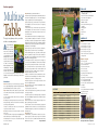
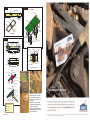
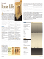
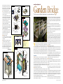
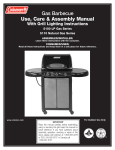
the
An Exclusive Lowe’s
Woodworkers Publication
woodpost
Summer 2006
entertain anywhere with this
multiuse
table
Enjoy this
complimentary issue of
Lowe’s The Wood Post
magazine. To sign up for
your FREE membership,
see details on the
back cover.
8 Router Table 11 Garden Bridge 13 Delta Woodworking Tools 18 Workshop Safety
Bill Sawyer,
Lowe’s Woodworkers
table of contents
The Pros Know
3
Multiuse Table
4
Router Table
8
Garden Bridge
11
The Right Tools
13
Workshop
19
Member Profile
19
Put It Together
20
P.S. Tell us about your projects or how you became interested in woodworking. Send
your responses c/o Sandy Culver, P.O. Box 523, Birmingham, AL 35201. If we profile
you in an upcoming issue of The Wood Post, you’ll receive a free Hitachi
14.4-volt 3⁄8-inch cordless drill/driver kit.
FREE TO MEMBERS!
As a member of Lowe’s Woodworkers, you are entitled to a free woodworking plan with each issue
of The Wood Post. Try out our plan for this tile-top
table (shown at left). It’s perfect for your outdoor
space and is available online until August 14, 2006.
Log on to Lowes.com/FreePlan.
PHOTOGRAPH: JOHN O’HAGAN
SAFETY IS YOUR RESPONSIBILITY: Lowe’s Companies, Inc., and its subsidiaries (“Lowe’s”), and SPC Custom Publishing, the Publisher of this issue of
The Wood Post, have made every effort to be complete and accurate in the instructions and other content contained in this Publication. However, neither Lowe’s
nor the Publisher assumes any responsibility or liability for damages or losses suffered, sustained, or incurred in the course of your home improvement, woodworking,
or repair project or in the course of your use of the item you create or repair. Further, improper use of handtools or power tools can lead to serious and permanent
injury or even death. In some issues of The Wood Post, the guards and safety equipment have been removed in illustrations and photos only to provide a better
view of the operation of the tool. Do not attempt any procedure or project unless all guards and safety equipment are in place. Always follow manufacturer’s operating
instructions in the use of tools. Check and observe all standard safety precautions.
2 Summer 2006
Q&A
With the Experts at
Q
Are there particular instances when I should
and should not predrill to assemble projects
with nails and screws?
A: You can almost never go wrong predrilling for assembly
when using either nails or screws. As long as the hole that you
drill is slightly smaller than the diameter of your fastener, you’ll
find that the fastener will go in more easily and accurately. In
some instances, however, it’s imperative that you predrill. If
you don’t predrill when you’re driving a fastener into the end of
a board, for instance, the fastener most likely will cause the end
to split. Likewise, if you’re screwing or nailing into the edge of
a board, predrilling prevents the fastener from splitting the
workpiece along its edge. Finally, some engineered materials,
particularly particleboard and medium-density fiberboard (MDF),
require predrilling; if you skip this important step, the edges
certainly will split.
Q
When I use my router, I often get dark marks
on the edge of the piece that I’m routing. Is
there a technique that I can use to prevent
this from happening?
A: The dark marks that you’re experiencing are most likely
burn marks caused by excessive friction. When there’s too
much friction, it creates overheating, which can burn or scorch
wood fibers. Friction can occur when using too slow a feed
rate, a dull bit, or the wrong type of pilot (for piloted bits). A
feed rate that’s too slow allows a sharp bit to rub against the
wood fibers enough to cause burning. A dull bit has a tendency
to tear wood fibers; because it doesn’t cut cleanly, you generally
have to slow the feed rate, which contributes to the problem.
Use a sharp bit and a moderate feed rate, and the burn marks
should go away.
Although most burn marks are caused by the bit’s cutting edge,
the pilot (if you’re using a piloted bit, such as a rabbeting bit)
also can be the culprit. The pilot may have either a ball bearing
or a rub collar. For the most part, a ball-bearing guided bit
leaves no burn marks because the bearing rolls along the
wood surface, allowing the bit to spin independently. Rub collars
by their very nature cause burning during a slow feed rate. To
eliminate this problem, replace rub collars with ball bearings.
Finally, it’s important to note that some wood types have a
reputation for burning, even with a sharp bit and moderate
feed rate. For the best results, make a series of light cuts
rather than one full-depth cut.
Q
Sometimes I need multiple pieces cut to
the same size for a project. Can I do this
efficiently, and accurately, without cutting
one piece at a time?
A: Production shops use a simple technique known as gang
cutting to cut multiple identical workpieces quickly and accurately.
Whether you’re using a miter, table, band, or scroll saw, stack
two or more workpieces on top of one another for the cut. On
a table saw, push the stacked parts past the blade using the
miter gauge. With a miter saw, press the stack right up against
the fence, and lower the blade. In either case, be sure to use
some form of a stop to keep individual pieces from shifting
during the cut; just make sure that the stop is as tall as your
stacked pieces.
For cuts on a band saw or scroll saw, your best bet is to attach
the pieces of the stack temporarily with double-sided tape to
keep them from shifting. One advantage of stacked cuts on
the band or scroll saw is that you will need to affix only one
pattern to the top piece to make the cut, rather than duplicating
the pattern for each workpiece.
n
PHOTOGRAPH: JOHN O’HAGAN
S
ummer outdoor entertaining offers the chance to combine great food, great
friends, and memorable experiences. Our multiuse table provides the perfect
centerpiece for your favorite dishes, as well as a focal point for your guests.
The project, a multipurpose adjustable table, is ideal for tailgating events and outdoor
concerts, plus it can serve as a dining table. Its ability to collapse gives folks with
limited space the option to have a large table for entertaining.
Our garden bridge is a great outdoor project that makes a big impact on any
landscape. Strolling across this piece will give you a sense of the craftsmanship
that goes into a project that’s both decorative and functional.
A router table is one way to make a highly versatile tool even more useful and
help any woodworker achieve amazing results. This project makes it easier than
ever to create decorative profiles and cut precise joinery.
Speaking of joinery, in Put It Together we take a look at one of the strongest
joints used in creating furniture—the mortise and tenon. In the Workshop column
our tips on saw blades will help you maintain these vital accessories and give them
a long life by keeping their edge.
As always, please tell us about your woodworking projects—what you have
created on your own or constructed from this issue, or any issue, of The Wood
Post. Write to me with your comments and suggestions, or visit us online at
Lowes.com/Woodworkers.
© 2006 Lowe’s Companies, Inc. All rights reserved. Lowe’s and the gable design are registered trademarks of LF, LLC. Lowe’s Companies, Inc., is the owner of copyright in the design, layout, arrangement, and presentation of this publication and is the owner of the copyright in certain materials in this publication. None of
these may be copied and reproduced in any manner or medium without the express written permission of Lowe’s Companies, Inc.
© 2006 SPC Custom Publishing. All rights reserved. SPC Custom Publishing has published this issue of The Wood Post for Lowe’s Companies, Inc., and owns copyright in materials SPC Custom Publishing has authored and materials taken from or derived from Creative Ideas for Home and Garden, Southern Living, and
Sunset magazines. None of these may be copied or reproduced in any manner or medium without the express written permission of SPC Custom Publishing.
From Our Shop
the pros know
Gang cutting produces multiple identical workpieces.
THE WOOD POST
3
feature project
TOOL LIST
Multiuse
Table
This project can play many roles in your outdoor
and indoor entertaining activities.
sturdy and adjustable
table is a must-have
for tailgating, outdoor
meals at home, or summertime
events such as open-air concerts.
Our activity table offers needed
flexibility for all these functions—
and more—with its adjustable
legs and a collapsible center. It
also makes a terrific auxiliary
dining or gaming table for folks
with limited space. Simply tuck
in the legs, fold the table in half,
and store it away when not in
use. You can finish the project with your favorite team’s colors for
tailgating, or substitute oak for poplar and apply a stain for a more
polished look.
A
Instructions:
General: Cut all parts as you assemble the project, using the Cut
List as a guide and adjusting as needed for fit. Attach all parts with
glue and 6d finishing nails unless otherwise specified.
Step 1: Build the skirt assemblies. Note that you will construct
two assemblies from the two halves of the table. Refer to Figure 1
for placement.
a. Cut the side skirts, end skirts, and center braces, and label the
pieces for reference.
b. Following the positioning and measurements shown in the side
skirt layout in Figure 1, drill holes in the side skirts for the locking
pins and leg assembly attachment.
c. Attach one end skirt to the end faces of a pair of side skirts;
repeat for the other half of the table.
d. Attach two center braces to the opposite end faces of the side
skirts; repeat.
e. Check both assemblies for square by measuring diagonally, and
attach temporary braces to maintain the square angles.
f. Clamp and glue the center spacer to the outside bottom edge
of one of the center braces.
4 Summer 2006
Step 2: Build the legs, and install the stiffeners.
a. Attach two upper legs flush together, and then drill a 3⁄8-inch hole
and a 1⁄4-inch hole through both pieces as shown; finish cutting per
the upper leg detail. Repeat for the remaining upper legs.
b. Clamp the upper legs to a work surface. Using a router with a
1
⁄4-inch straight bit, rout a 1⁄4-inch slot into each (see the upper leg
detail in Figure 2).
c. Clamp the lower legs to a work surface. Using a router with a
1
⁄4-inch straight bit, rout a 1⁄4-inch slot into each (see the lower leg
detail in Figure 2). Also drill a 1⁄4-inch hole and cut a notch in each,
as shown in the detail.
d. Sand, and finish as desired prior to assembling the leg pieces.
e. Apply self-adhesive sandpaper to the inside face of each upper
leg assembly (see Figure 2, upper leg detail). Note: The sandpaper
will help grip the lower leg in any position (especially when extended).
f. Attach lower legs to upper legs using hex bolts, fender washers,
and bar knobs as shown in Figure 2.
g. Attach upper legs to side skirts using hex bolts, flat washers,
flat nylon washers, and crown hex nuts as shown in Figure 2.
h. Clamp a framing square onto a leg assembly to hold it square
with its side skirt. Then, using the 1⁄4-inch hole in the side skirt as a
guide, drill a 1⁄4-inch hole through the upper leg for the locking pin.
Repeat with remaining leg assemblies.
i. Temporarily thread a brass wing nut onto the locking pin to
secure the legs in the folded-down position. Note: The locking bolt
will secure the leg assembly when the table is closed for storage.
j. Use a 1⁄16-inch nylon washer as a spacer between the outer faces
of a pair of upper legs and the inner face of the first stiffener, with
the stiffener resting on the shoulder of the legs (see Figure 3).
k. Attach the stiffener to the side skirts.
l. Attach a second stiffener to each side skirt and the face of the
first stiffener so that the bottom edges of the stiffeners are flush.
m. Repeat Steps 2j–2l for the second leg assembly.
n. Attach the leg spacers to the lower legs at the locations shown
in the lower leg detail in Figure 2.
Step 3: Complete the top assembly, and add hardware. Note:
See Figure 3 for placement.
a. Cut the top panels per the Cut List.
b. Scribe the long and short nosings, and miter cut to fit. Attach
the nosings per Figure 3.
c. Attach the top panels to the skirt/leg assembly, centering from
side to side and aligning the edge of the top panel with the edge of
the center braces.
d. Attach the two halves of the table using a piano hinge (refer to
Figure 3, piano hinge/sash lock detail).
e. Attach the three sash locks under the tabletop, spacing them
equidistant from each other. Be sure to place them proportionally
for maximum stability. The sash locks will secure the tabletop in its
extended position.
Step 4: Apply a finish.
a. Fill all nail holes, sand, and finish as desired. See the photographs on page 6 if you plan to stain your project. For our painted
version of the table, we used American Tradition, Homecoming
Blue #4009-9, semi-gloss).
Project #SU061 I
• table saw (or circular saw with a
straightedge guide)
• miter saw (or miter box and handsaw)
• router with 1⁄4-inch straight bit
• band saw (or jigsaw)
• drill/driver and bits
• power sander and various grits of
sandpaper
• framing square
• clamps
• tape measure
• pencil
LOWE’S LIST
Lumber*
• 1 (6-foot-long) 1 x 2, poplar
• 2 (8-foot-long) 1 x 2s, poplar
• 4 (2-foot-long) 1⁄2 x 3s, poplar
• 4 (8-foot-long) 1 x 4s, poplar
• 1 (10-foot-long) 1 x 4, poplar
• 1 (48- x 96-inch) sheet of 3⁄4-inch-thick
birch plywood
Hardware & Supplies
• 4 (3⁄8 x 3) hex bolts
• 16 (1 x 13⁄32 x 1⁄16) flat nylon washers
• 4 (3⁄8-inch) flat washers
• 4 (3⁄8-inch) crown hex nuts
• 8 (1⁄4 x 3) hex bolts
• 4 (1⁄4 x 31⁄2) hex bolts
• 1 package (1⁄4-inch) fender washers
• 8 (1⁄4 x 20) bar knobs
• 4 packages (1⁄4 x 20) brass wing nuts
• 1 (11⁄2- x 30-inch) piano hinge
• 1 box 6d bright finishing nails
• 1 (6-ounce) tube stainable wood filler
• wood glue
• 3 sash locks
• 1 (10-yard) roll self-adhesive sandpaper
• 1 quart stain or paint
PHOTOGRAPHS: JOHN O’HAGAN
CUT LIST
Part Name
Material
Size (in inches)
Quantity
side skirts
end skirts
center braces
center spacer
stiffeners
upper legs
lower legs
leg spacers
top panels
long nosing
short nosing
(10-foot-long) 1 x 4
(8-foot-long) 1 x 4
(8-foot-long) 1 x 4
1x2
1x2
(8-foot-long) 1 x 4
(8-foot-long) 1 x 4
1
⁄2 x 3
(3⁄4-inch) plywood
(8-foot-long) 1 x 4
(8-foot-long) 1 x 4
⁄4 x 21⁄2 x 2911⁄16
3
⁄4 x 21⁄2 x 221⁄4
3
⁄4 x 21⁄2 x 221⁄4
3
⁄16 x 3⁄4 x 221⁄4
3
⁄4 x 11⁄2 x 201⁄2
3
⁄4 x 21⁄2 x 173⁄16
3
⁄4 x 21⁄2 x 153⁄4
1
⁄2 x 21⁄2 x 161⁄4
3
⁄4 x 281⁄2 x 347⁄16
3
⁄4 x 3⁄4 x 3515⁄16
3
⁄4 x 3⁄4 x 30
4
2
4
1
4
8
4
4
2
4
4
3
*Availability varies by market.
The 1⁄4-inch slot in each leg piece allows
the height of the table to be adjusted.
THE WOOD POST
5
Figure 3
Figure 1
3/8" hole
29 11/16"
top assembly
side skirt layout
short nosing
center of table
end of table
1 7/16"
11/16"
13/16"
1/4" locking-pin hole
(open position)
10 1/8"
6 1/2"
1/4" locking-pin hole
(folded position)
side skirt
top panels
center braces
side skirt
end skirt
long nosing
spacer 3/16" x 3/4"
applied to one
assembly only
end skirt
1/16” spacer
and two stiffeners
skirt assembly
1/16” spacer
and two stiffeners
Figure 2
17 3/16"
3/8" hole
5/8"
skirt / leg assembly
leg spacers
add sandpaper to this area on inside face
5/8"
leg spacers
1/4" hole
1/4" wide slot
7/8"
2 1/2"
2 1/2"
1 1/4"
13/16"
7/8"
2 1/4"
11 3/4"
15 3/4"
short nosing
7/8"
piano hinge
short nosing
top panel
top panel
upper leg detail (8 required)
side skirt
15 3/4"
1" x 3/4" notch
1 1/2"
side skirt
4"
leg spacer
7/8"
2 1/2"
center braces
7/8"
1/4" hole
12"
5/8"
center braces
CL
1/4" slot
2 1/4"
7/8"
lower leg detail (4 required)
3/16” x 3/4” spacer
sash lock
piano hinge / sash lock detail
Step 2f
1/4" fender washer
1/4 x 20 bar knob
upper leg
1/4 x 3 hex bolt
lower leg
1/4" fender washer
Step 2g
3/8" crown hex nut
1 x 13/32 x 1/16
flat nylon washers
3/8" flat washer
1/4 x 20
wing nut
1/4 x 3 1/2 hex bolt
(locking pin)
3/8 x 3 hex bolt
Finished Dimensions:
Height: 18–30 inches
Depth: 72 inches
Width: 30 inches
6 Summer 2006
ABOVE, LEFT: Besides being painted,
the activity table also can be stained.
Here, we used Olympic, Golden Oak.
If staining, be sure to substitute oak
for the poplar.
ABOVE: The lower legs of this table
are adjustable from the full height of
30 inches down to 18 inches.
LEFT: Sash locks along the centerline
of the table stabilize the top when it is
in the extended position.
feature project
a. To make the template, first measure the distance from the cutting edge of a 1⁄4-inch straight bit to the outside edge of the router
base plate to determine its offset.
b. Then cut a plywood square to measure 9 inches plus twice the
router base offset plus 6 inches.
c. Locate and draw centerlines on the template. Then lay out a
square measuring 9 inches plus twice the offset, centered on these
centerlines.
d. Drill an access hole for a jigsaw within the square, and cut it out.
e. To rout the recess in the top, set a 1⁄4-inch straight bit fitted in your
router for a 1⁄4-inch-deep cut. Then center the template over the 7inch-square hole cut in the top assembly, and temporarily attach
with screws. Now rout out the material along the inner edges of the
template to create a 1⁄4-inch-deep recess around the 7-inch hole.
Use a chisel to square up the corners of the routed area.
f. For a general-purpose base plate, use a drill/driver with a 11⁄2-inch
hole saw attachment to cut a hole in the center of the acrylic plate.
Consider making several base plates with center holes cut in a
variety of sizes for different bits.
Router Table
portable router by itself is a versatile
tool. But you won’t know everything
it can do until you mount your router
to a table. When you flip a router upside
down, mount it, and add fences, you basically turn it into a shaper: You’re able to cut
joinery with precision and rout decorative
profiles with ease. Our router table features
independently adjustable sliding fences and
a push bar that glides along a groove in the
tabletop. By mounting your router to an
acrylic base plate recessed into the table, you
can lift the router up and out conveniently to
change bits and make adjustments.
A
Instructions:
General: Cut all parts as you assemble the
project, using the Cut List as a guide and
adjusting as needed for fit. Use glue and the
appropriate length nails to attach all parts
unless otherwise specified.
Step 1: Build the fences. See Figure 1.
a. Drill a 5⁄16-inch hole 11⁄4 inches in from each
end of the slide bottom; center the holes
lengthwise as shown.
b. Attach two slide sides to the slide bottom
per Figure 1.
c. Drill a 5⁄16-inch hole 2 inches in from each
end of the slide face.
d. Center and attach a slide face from side
to side on the slide assembly.
e. Insert a bar knob and elevator bolt into
the two holes in the slide face.
f. Attach the face, face spacers, and face
backs per Figure 1. This assembly attaches
to the slide face with the elevator bolt.
g. Repeat Step 1 to create a second fence.
Step 2: Build the push bar. Note: The push
bar is similar to the miter gauge on a table
saw. It’s built just like the sliding fences in
Step 1, except that the face is replaced with
a sacrificial board, and it has a guide that fits
in a groove in the tabletop. See Figure 2.
a. To make the base of the push bar, repeat
Steps 1b and 1d for the bar sides, bottom,
and face.
b. Using glue and screws, attach the guide
8 Summer 2006
to the bottom of the push bar assembly so
that it is centered and perpendicular to the
face. Rounding the corners slightly will help
the guide slide smoothly in the tabletop.
c. Attach the sacrificial board to the bar face
using screws; with use, it will get chewed up
and need to be rotated and/or replaced.
Step 3: Build the top assembly. Note:
Before you begin assembling the top, you’ll
want to measure your router to verify that it
will fit through a 7-inch-square hole; if it will
not, modify the hole dimensions as needed.
See Figure 3.
a. Locate and draw centerlines on the subtop. Lay out a 7-inch square that’s centered
on the centerlines.
b. Drill an access hole within the square for
a jigsaw, and then cut out the 7-inch square
on the sub-top.
c. On the mid-top, measure and mark a line
12 inches in from the long back edge per
the layout detail. Measure and mark a line 9
inches in from each short edge as shown.
These are the centerlines of the material that
you’ll remove to form the slots.
d. Drill a 11⁄4-inch hole at the intersections of
the 9- and 12-inch centerlines on the mid-top.
e. Use a framing square to locate the apex
on either side of the 11⁄4-inch holes. Mark a
line that extends from the apex to the back
edge of the mid-top.
f. Cut along these lines, and then remove
the material to create the slots.
g. Locate the center of the 12-inch line on
the mid-top, and draw a line perpendicular to
it. Then lay out a 7-inch square centered on
the intersection of these lines.
LEFT: The push bar
guides stock routing
and helps apply
even pressure.
RIGHT: The fences
adjust via elevator
bolts and grooves
in the top assembly.
PHOTOGRAPHS: JOHN O’HAGAN
Simplify edges and joinery and expand your capabilities
by mounting your router in this table.
h. Drill an access hole for a jigsaw within the
square, and then cut out the 7-inch square.
i. Attach the mid-top to the sub-top so that
the edges are flush.
j. Attach the front edging to the top of the
sub-/mid-top assembly so that the front
edges are flush.
k. Lay out the top as shown in the layout
detail in Figure 3 (as in Step 3c).
l. Repeat Step 3g on the top.
m. Drill a 5⁄16-inch hole at the intersections of
the 9- and 12-inch.
n. Repeat Steps 3e and 3f to locate and cut
slots in the top for the elevator bolts.
o. Repeat Step 3h for the top.
p. Attach the top to the sub-/mid-top assembly so that the sides and back edges
are flush; this creates a 3⁄4-inch groove in the
top assembly for the push bar.
Step 4: Add the acrylic base plate. Note:
To make it easy to change bits, you’ll replace
the base plate on your router with a 9-inchsquare acrylic base plate that fits into the
recess in the top assembly. This allows you
to push the router and base plate up from
underneath to set the router on the router
table for bit changing. The most accurate
way to rout this recess is to use a template.
TOOL LIST
• table saw
• power miter saw (or handsaw with miter box)
• router with 1⁄4-inch straight bit
• power sander and various grits of sandpaper
• drill/driver and bits
• countersink bit
• 11⁄2-inch hole saw attachment
• Kreg ProPack Pocket Hole System
• jigsaw
• chisel
• hammer
• bar clamps
• framing square
• straight edge
• tape measure
• laundry marker
• pencil
LOWE’S LIST
Lumber*
• 2 (6-foot-long) 1 x 2s, poplar
• 4 (3-foot-long) 2 x 2s, poplar
• 3 (6-foot-long) 1 x 4s, oak
• 2 (8-foot-long) 1 x 4s, poplar
• 1 (48- x 96-inch) sheet of 1⁄4-inch-thick birch plywood
• 1 (48- x 96-inch) sheet of 3⁄4-inch-thick mediumdensity fiberboard (MDF)
Hardware & Supplies
• 8 (5⁄16-inch x 18) bar knobs
• 8 (5⁄16-inch x 18) elevator bolts
• 1 (1⁄4- x 24- x 24-inch) clear acrylic sheet
• 1 box (11⁄4-inch) Kreg pocket hole screws
(fine thread)
• 1 box (#18 x 3⁄4-inch) wire brads
• wood glue
• 1 quart polyurethane
*Availability varies by market.
g. Remove the base plate from your router, and center it on the hole
in the acrylic base plate. Use a laundry marker to mark the mounting
hole locations of your base plate on the acrylic plate. Then drill the
appropriate size screw holes at these locations, countersinking these
holes so that the mounting screws will sit flush with the surface of
the acrylic.
h. Attach the acrylic base plate to your router with the mounting
screws, and test how the plate fits in the recess; trim as needed
with a chisel.
Step 5: Build the stand; see Figure 4.
a. Using a pocket hole jig, drill two holes for pocket hole screws in
each end of all skirt pieces and all stretchers.
b. Position a side skirt flush with the tops of a pair of legs, and then
assemble with glue and pocket hole screws. Position a side stretcher
so that its bottom edge sits 4 inches up from the base of the legs;
attach to the legs with glue and pocket hole screws. Repeat for the
other side assembly.
c. Position a skirt between the two side assemblies with top edges
flush, and attach with glue and pocket hole screws. Place a stretcher
CUT LIST
Part Name
(for fences)
slide sides
slide bottoms
slide faces
face backs
face spacers
faces (for push bar)
bar sides
bar bottom
bar face
guide
sacrificial board
(for top assembly)
sub-top
mid-top
front edging
top
base plate
(for stand)
side skirts
skirts
legs
stretchers
side stretchers
shelf
stile nailers
bottom nailers
back bottom nailer
sides
back
fillers
corner blocks
Material
Size (in inches)
1 x 4, oak
1 x 4, oak
1 x 4, oak
1 x 4, oak
birch plywood
1 x 4, oak
1 x 4, oak
1 x 4, oak
1 x 4, oak
1 x 4, oak
1 x 4, oak
⁄4 x 31⁄2 x 6
⁄4 x 31⁄2 x 6
3
⁄4 x 31⁄2 x 12
3
⁄4 x 19⁄16 x 16
1
⁄4 x 11⁄8 x 16
3
⁄4 x 31⁄2 x 16
3
⁄4 x 31⁄2 x 6
3
⁄4 x 31⁄2 x 6
3
⁄4 x 31⁄2 x 12
3
⁄4 x 3⁄4 x 12
3
⁄4 x 31⁄2 x 16
4
2
2
4
4
2
2
1
1
1
1
MDF
birch plywood
MDF
MDF
acrylic sheet
3
⁄4 x 24 x 32
⁄4 x 24 x 32
3
⁄4 x 41⁄8 x 32
3
⁄4 x 191⁄8 x 32
1
⁄4 x 9 x 9
1
1
1
1
1
1 x 4, poplar
1 x 4, poplar
2 x 2, poplar
1 x 4, poplar
1 x 4, poplar
MDF
1 x 2, poplar
1 x 2, poplar
1 x 2, poplar
birch plywood
birch plywood
1 x 2, poplar
1 x 4, poplar
⁄4 x 31⁄2 x 151⁄2
⁄4 x 31⁄2 x 21
11⁄2 x 11⁄2 x 341⁄4
3
⁄4 x 31⁄2 x 21
3
⁄4 x 31⁄2 x 151⁄2
3
⁄4 x 181⁄2 x 24
3
⁄4 x 3⁄4 x 221⁄2
3
⁄4 x 3⁄4 x 14
3
⁄4 x 3⁄4 x 191⁄2
1
⁄4 x 151⁄2 x 241⁄2
1
⁄4 x 21 x 251⁄4
3
⁄4 x 11⁄2 x 151⁄2
3
⁄4 x 31⁄2 x 31⁄2
2
2
4
2
2
1
6
2
1
2
1
2
4
3
3
1
3
3
Quantity
THE WOOD POST
9
Project #SU062
n
skirt
filler
Completed Project
stile nailers
side skirt
fence
back bottom
nailer
top assembly
filler
fence
skirt
side
back
side
leg
push bar
side skirt
stile nailers
shelf
stretcher
corner
block
stand
10 Summer 2006
bottom nailer
side stretcher
weekend project
Garden Bridge
This classic project will add a striking feature to your yard or landscape.
PHOTOGRAPH: JOHN O’HAGAN / STYLING: LEIGH ANNE MONTGOMERY
between the two side assemblies so that
Figure 1
Figure 2
the bottom edge of the stretcher sits 4
bar sides
bar bottom
1 1/2"
inches above the base of the legs; attach
guide
slide bottom
1
1/4"
2
9/16"
with glue and pocket hole screws. Repeat
sacrificial
6"
3 1/2"
board
for the remaining skirt and stretcher.
6"
bar sides
3 1/2"
d. Cut 11⁄2-inch-square notches on each
slide sides
corner of the shelf. Attach the shelf to the
bar face
C
slide face
slide bottom
tops of the stretchers.
1 1/4" L
e. To create a nailing surface for the sides
slide side
face
Figure 3
and back, attach stile nailers flush with the
face of the legs; attach the bottom nailers
face back
and back bottom nailer to the top of the
base plate
shelf, flush with the stile nailers.
face spacer
f. Secure the sides and back to the nailers
face spacer
slide face
and skirts using glue and brads.
face back
slide sides
face
g. Install the fillers between the legs at
front edging
top
the top of each side assembly so that the
top edges of the fillers are flush with the
face
assembly
top edges of the side skirts.
bar knob
forms slot
h. To create an attachment surface for the
elevator bolt
mid-top
for elevator
bolt
top, cut triangular corner blocks from a 1 x
Side View of Fence
4 poplar board, and attach them in the
upper corners of the stand.
Step 6: Final assembly.
a. Center the top assembly on the stand, and
Layout Detail
sub-top
secure it by driving screws up through the
CL
back edge
corner blocks.
9"
9"
b. Fill all nail holes, sand; finish as desired.
Finished Dimensions,
c. Position the push bar in its groove.
12"
7"
Installed:
CL
7"
d. Insert an elevator bolt and bar knob into
Height: 391⁄2 inches
each of the four holes in the bases of the
Depth: 24 inches
fence assemblies; slide the bolts into their slots.
Width: 32 inches
When using the router table, align the faces of
Figure 4
the two fences using a straightedge.
ou don’t need to have a babbling brook in your backyard to
find the perfect location for this simple, yet elegant, garden
bridge; build it over a small pond, uneven terrain, or even a
low patch. The bridge shown is 8 feet, 41⁄2 inches long, but it can
span a maximum length of 11 feet, 10 inches with the 2 x 8 boards
laid out at 16 inches on center. If you would like to build a longer bridge
that is supported only at its ends, we suggest that you first check out the
American Wood Council Web site at www.awc.org/technical/spantables
to verify the size of the joists needed to support your desired span.
Y
Instructions:
General: Cut all parts as you assemble the project, using the Cut
List as a guide and adjusting as needed for fit. Note that it is best to
purchase treated wood a few weeks before you plan to use it. Stack
your treated boards, with spacers, in a dry place and turn on a fan.
Allow the boards to air dry. Also note that even when it is no longer
damp, pressure-treated wood tends to be quite heavy. So it’s better
to assemble this bridge on-site rather than to build it in the shop and
then transport it to its final location.
Step 1: Make the joist/box sill assembly.
a. Use a framing square to verify and cut one end of each joist so that
it is square. If any of the boards is out of square, trim only the amount
necessary to form a right angle. (Boards usually measure slightly
longer than labeled to allow for squaring. For example, an 8-foot-long
board usually measures 96 inches plus.) Cut and square the other
joist ends so that all measure 96 inches long.
b. Use 16d galvanized finishing nails to attach the two box sills to
the two outside joists (see Figure 1).
c. Measure 13 inches from the inside faces of both outside joists
for placement of the other two. Attach with 16d galvanized nails.
d. Check the assembly for square by measuring diagonally at the
corners, and adjust as needed until the two diagonal measurements
are equal.
Step 2: Prepare the location for installation of the bridge.
a. Lay out, stake, and square the location of the four posts. The
centers of the posts are 941⁄4 inches apart in length and 443⁄4 inches
apart in width.
b. At each marked corner, dig a hole that measures approximately
12 inches square and 22 inches deep. Add sand to the bottoms of
the holes until they are 18 inches deep.
Step 3: Secure the posts.
a. Place the posts in the holes, and use a level to check for plumb
both vertically and horizontally. Uses stakes and scrap lumber to
temporarily secure each post, and add enough dry concrete mix
to the holes to stabilize the posts. Tamp the concrete mix in place.
b. Mix enough wet concrete per the manufacturer’s instructions to
fill the balance of the holes. Pour concrete into the holes until it is
just above ground level, and then trowel the top of the concrete to
slope it away from the posts in all four directions. Let the concrete
cure overnight.
Step 4: Install posts and cleats.
a. Using 16d galvanized nails and lag screws, attach the posts to the
joist/box sill assembly (see Figure 2). Drive in the top or bottom
nail first, and then use a level to check each post for plumb (vertically
level) before driving in the remaining nails.
b. Use a framing square to scribe a line on the interior faces of each
post at the point where the post meets the top of the joist; these
lines will allow you to position wood to support the decking.
c. Align the tops of the cleats with the scribed lines. Attach with
construction adhesive and 21⁄2-inch outdoor wood screws.
Step 5: Add the decking.
a. Lay an end piece of decking against a pair of end posts with the
decking overhanging the box sill and the outside joists by 3⁄4 inch on
each side.
b. Scribe the locations of the posts on the piece of decking (see
Figure 3).
c. Use a jigsaw to cut a 33⁄8-inch-deep notch for each end post
(see Figure 3, Detail A). Repeat this process for the other end piece
of decking.
d. Use a drill/driver with the appropriate bit to attach the end decking
to the joist/box sill assembly with 21⁄2-inch outdoor wood screws.
e. Use 16d nails as spacers between the end piece and second piece
of decking at both ends of the bridge. Attach each second piece of
decking with outdoor wood screws.
f. Install the two center pieces of decking next by repeating Steps
5a–3e. Cut the notches for the center posts to fit, about 111⁄16 inches
THE WOOD POST
11
deep on each center piece, as shown in
Figure 3, Detail B.
g. Lay the remaining 12 pieces of decking in
place. Space them with even gaps, and then
attach using outdoor wood screws. Remove
the nails serving as spacers between the
first and second pieces of decking.
Step 6: Install the rails and handrails.
a. Identify a centerline on each post to guide
you when positioning the fence rail brackets.
Also measure and mark a line on each post
that’s 8 inches up from the top of the decking;
repeat at 191⁄2 inches and 315⁄16 inches above
the decking (see Figure 4).
b. Attach the fence rail brackets to the posts
using Simpson Strong-Drive wood screws so
that the bottom of each bracket aligns with
your marks on each post and the bracket is
centered on the centerline.
c. Mark or scribe each rail, and cut to fit
(approximately 421⁄2 inches from post to post).
Use three Simpson Strong-Drive screws
at each bracket to install the rails.
d. Mark or scribe the handrail pieces, and cut
to fit. Attach the handrails to the top railing
with 16d galvanized nails.
Step 7: Apply the finishing touches.
a. Attach a copper postcap to the top of each
post using a small amount of construction
adhesive and 4d galvanized finishing nails.
b. Apply the exterior stain of your choice.
Project #SU063
Figure 1
the right tools
CUT LIST
Part Name
Material
Size (in inches)
Quantity
joists
floor beams
posts
cleats
decking
rails
handrails
2 x 8, TYSP
2 x 8, TYSP
4 x 4, TYSP
2 x 4, TYSP
5
⁄4 x 6, ChoiceDek
2 x 4, TYSP
13⁄16 x 31⁄2, ChoiceDek
11⁄2 x 71⁄4 x 96
11⁄2 x 71⁄4 x 461⁄2
31⁄2 x 31⁄2 x 641⁄2
11⁄2 x 31⁄2 x 31⁄2
5
⁄4 x 51⁄2 x 48
11⁄2 x 31⁄2 x 421⁄2
13⁄16 x 31⁄2 x 423⁄4
4
2
6
14
18
12
4
TOOL LIST
Figure 3
decking
center post
end post
joists
end piece of
decking
second piece
1/8" gap
1 11/16"
1 11/16"
n
1/8" gap
post
C
Detail B L
scribe
to fit
2 1/4"
3/4"
1/8"
post
scribe
to fit
3 1/4"
2 1/4"
3/4"
Detail A
Figure 4
2 x 4 fence
bracket
Figure 2
/16"
31 5
concrete
sand
12 Summer 2006
handrail
rail
box
sill
post
Lowe’s stocks the largest selection of Delta woodworking tools nationwide, and this is the perfect
opportunity to make a Father’s Day wish list. Check off the tools you’d like to receive, and strategically
set these pages where they’ll be noticed by your loved ones.
Because tool availability varies by market, be sure to provide the manufacturer’s name and model
number at your store’s customer service desk.
Table Saws and Accessories
Lumber*
center pieces
13"
cleat
Headquarters
LOWE’S LIST
3/4"
box
sill
• circular saw or handsaw
• jigsaw
• drill/driver and bits
• framing square
• level
• caulking gun
• tape measure
• pencil
Delta Woodworking
19
"
1/2
8"
Finished Dimensions:
Height: 461⁄2 inches
Width: 48 inches
Length: 1001⁄2 inches
• 7 (8-foot-long) 2 x 4s, treated
southern yellow pine (TSYP)
• 6 (8-foot-long) 4 x 4s, TSYP
• 5 (8-foot-long) 2 x 8s, TSYP
• 6 (12-foot-long) 5⁄4 x 6s,
ChoiceDek Premium gray
woodgrain decking
• 2 (12-foot-long) 13⁄16- x 31⁄2-inch
ChoiceDek gray handrails
Hardware & Supplies
• 1 box (16d) galvanized
finishing nails
• 1 box (#8 x 21⁄2-inch) Phillips
II outdoor wood screws
• 8 (3⁄8-inch x 4-inch) lag screws
• 4 (50-pound) bags all-purpose
sand
• 4 (50-pound) bags all-purpose
concrete mix
• 1 box (4d) galvanized
finishing nails
• 1 box (SD8) Simpson
Strong-Drive wood screws**
• 24 (2 x 4) fence rail brackets
• 6 Maine Ornamental 4 x 4
Victoria Copper High Point
Postcaps
• construction adhesive
• exterior stain
• paint (American Tradition,
exterior latex, white)
36-979 Industrial Contractor’s Saw
This 10-inch left-tilt table saw (#237665) has a 11⁄2-horsepower (hp),
115/230-volt induction motor that can handle tough cutting operations.
The 0- to 45-degree bevel tilts the blade away from the fence (left tilt) in
ripping applications to prevent tear-out on the outside corner of mitered
joints. The saw features cast-iron extension wings measuring 40 x 27
inches for maximum material support. It also includes a mobile bottom
that attaches directly to the base for full saw support and mobility. The
saw accommodates multiple fences, including the T2 30-inch fence
system, the 30-inch Unifence, and the Biesemeyer 30-inch commercial
fence system.
TS350 ShopMaster 10-inch table saw
Make precise cuts with this sturdy table saw (#33719). It features a 1-hp, 120-volt,
single-phase induction motor for plenty of power. The miter gauge has adjustable
stops at 90 degrees and 45 degrees, left and right, for precise straight and angle
cutting. It has a self-aligning T-square fence with a single control handle for convenient accuracy. For safety, it features a see-through blade guard with a splitter and
antikickback fingers, as well as a removable on/off switch to prevent unauthorized
use of the machine. In addition to a cast-iron carriage, which allows for precision
and minimal vibration, a solid undertable features a cast-iron trunnion, motor, and
trunnion support brackets.
*Availability varies by market.
**Selection varies by market.
THE WOOD POST
13
the right tools
Fence Systems
These offer a three-point T-square locking system with a hairline pointer to assure that the fence is
parallel to the blade and accurate to within 1⁄64 inch. All three of these fence systems fit the 36-979
Industrial Contractor’s Saw (#237665).
NEW
36-T30 T2 30-inch fence system
The face of the T2 fence (#237669) is made from extruded
aluminum and attaches to the solid-steel angle iron and tubing
for years of durability. The fence clamps to both the front tube and
rear rail of your table saw to accommodate various fence attachments.
The easy-gliding fence body can handle quick, repetitive cutoff work, precision
ripping, and squaring cuts. The fence also can be removed quickly for placement
on either side of the blade for consistent ripping on left or right tilt saws. It includes
an additional rear hold-down support for use with jigs and featherboards.
NEW
36-U30 Unifence fence system
The Unifence system (#237666) includes the fence, rail, leg set,
adjustable stop, and 14-inch-wide tableboard. The dual-position fence
rotates from 31⁄3-inch-tall stock to 1⁄2-inch-thin stock for maximum versatility of
materials, including laminated boards that overhang the fence. At 43 inches long,
the fence can be positioned forward of the blade to align large panels better during ripping
and to function as a stop for repetitive crosscuts. The infinitely adjustable stop, with flipdown bypass, positions the fence at preset measurements for fast and consistent fence
adjustments. The tableboard offers 30 inches of material support to the right of the blade.
Planers and Jointers
JT360 6-inch deluxe jointer
Ensure that your wood surfaces are flat with this deluxe jointer (#60009).
The 3⁄4-hp model features a 47⁄8- x 35-inch fence that mounts in the center
for maximum work support and tilts for beveling and chamfering operations. It
also includes a heavy-gauge steel stand and wide footprint for sturdy support
and a built-in dust chute to direct dust and chips away from the operator. The
safety cutterhead guard pivots out of the way of work during operation. The 46-inchlong table can handle extra-long stock. The equipment features a cast-iron wedge
bed for solid support, and fully adjustable infeed and outfeed tables that operate on
gibbed dovetailed ways to compensate for wear. The infeed table also has a castiron, 83⁄4- x 3-inch support ledge for rabbeting operations.
JT160 ShopMaster 6-inch variable-speed bench jointer
This jointer (#33781) has variable speed ranges of 6,000 to 11,000
revolutions per minute (rpm), or 12,000 to 22,000 cuts per minute
(cpm). It allows you to select the correct speed for the size and
hardness of the material that you cut. The center-mounted
fence gives support throughout the cut for accurate edge
jointing. The fence tilts 0 to 45 degrees outward for bevel
jointing and chamfering and features positive stops at
45 and 90 degrees. The Poly V belt drive offers maximum
transmission of power to the cutterhead with minimum belt slippage.
Balanced for smooth operation and a maintenance-free life, the twoknife cutterhead has a jackscrew-knife leveling arrangement for easy
replacement and adjustment of individual knives. The built-in chip
chute directs dust and chips away from the operator, motor, and electrical
components, while the extra-large table provides ample work support for
surfacing stock up to 6 inches wide.
NEW
36-B30 Biesemeyer 30-inch commercial fence system
The Biesemeyer system (#237671) includes the fence, rail, leg set, and 14inch-wide tableboard. It has a rugged construction of high-impact laminated
birch plywood that is hand-fitted to the solid-steel angle iron and tubing for years of
continuous use. The fence and head are made of heavy-gauge steel for lifelong accuracy
with no deflection.
14 Summer 2006
TP305 ShopMaster 121⁄2-inch portable planer
Follow up your surfacing efforts with this portable planer (#36274). The
powerful 15-amp, 120-volt motor offers superior stock removal. The twoknife, quick-change, solid-steel cutterhead is mounted on ball bearings for
smooth operation and long life, and high-speed steel, two-edge/reversible
knives double the cutting life. The patented cutterhead elevation on four
precision-ground columns offers superior cut stability. The planer includes a
convenient wood-return roller and adjustable infeed and outfeed tables.
THE WOOD POST
15
the right tools
Belt/Disc Sander
Scroll Saw
31695 6-inch belt/9-inch disc sander
This sander (#201452) features a 1-hp, 120-volt induction motor that is completely
enclosed for protection against dust. The belt unit is adjustable so that the sander can
operate vertically, horizontally, and at in-between angles, and the belt guard removes
to allow for contour sanding. The 9-inch disc is perfect for sanding large curves or
rounding out sharp corners. The cast-aluminum table can tilt 45 degrees for bevel
sanding, and it accommodates either the belt or disc unit. A belt-tracking knob
provides tool-free belt alignment, and a belt-tensioning lever loosens and tightens
the belt instantly for quick belt changes. The sander also features a 21⁄4-inchdiameter dust outlet for adaptation to a dust-collection system or shop vacuum.
SS350LS Industrial 16-inch variable-speed scroll saw with leg set
This scroll saw (#178013) offers a heavy-duty, 2-amp, 120-volt induction motor. The
patented upper and lower blade chucks feature the Quickset II Blade Chuck System
for quick, tool-free blade changes. The teardrop-shaped, cast-iron table tilts 0 to 45
degrees and extends the full length of the throat for maximum workpiece support. The
variable speed control of 600 to 1,650 cutting strokes per minute (cspm) is designed
for cutting wood, metal, and plastics. A built-in air blower keeps the cutting line free of
dust, and the saw includes a removable dust-collection box with a 11⁄2-inch dust port.
Also included are a convenient carrying handle and blade storage area.
Band Saws
Minimize waste and maximize efficiency with band saws from Delta.
Create both curved and straight lines with these versatile machines.
BS150LS 10-inch band saw with stand
This band saw (#33307) features a heavy-duty, 1⁄2-hp
ball-bearing motor and upper and lower tire brushes
for improved blade tracking. The cast-iron frame and
table offer improved stability, and the large, two-wheel
design extends blade life. The rack and pinion tabletilt adjustment positions the table at any angle from 3
degrees left to 45 degrees right, and the upper-blade
guide adjustment allows for precise height positioning.
The band saw has a maximum capacity of 10 inches
from frame to blade.
Drill Press and Accessories
DP300L 12-inch bench drill press with laser
Featuring a 1⁄3-hp, 120-volt induction motor for long-lasting, smooth performance, this drill
press (#99686) has a pivoting motor mount that maintains correct belt tension and facilitates
speed changes. The three-spoke pilot wheel offers convenience for the operator, and the
adjustable-position, locking depth stop allows for accurate depth measurement and repetitive drilling. The tilting table features slots for fast clamping of workpieces. The standard threejaw, 1⁄2-inch-capacity chuck provides positive gripping of various drill press cutting tools. Laser-guided
operation provides unparalleled accuracy.
17-940 25-piece sanding drum kit
This kit (#237677) converts a drill press for use as a sander. It includes five drums with 1⁄2-, 3⁄4-, 1-, 11⁄2-, and 2inch diameters and fits drill presses with 1⁄4-inch and larger chucks. The kit comes in a carrying case with
two sets each of 80- and 120-grit sanding sleeves.
Miter Saw
28-276 Industrial 14-inch band saw with stand
This model (#59964) has a capacity of 133⁄4 inches from frame to blade and features a 3⁄4-hp,
120-volt motor that is ideal for contour cutting, straight cutting, and resawing operations. It
features the Rapid-Release tension lever and a nine-spoke wheel. The 16- x 16-inch cast-iron
table tilts 3 degrees left and 45 degrees right for beveling operations. The lower blade guides
will angle to support the blade to within 3⁄4 inch of the table work surface to ensure accurate
cutting. The saw includes a 4-inch integral dust port.
16 Summer 2006
36-322L Industrial TwinLaser 12-inch compound miter saw
The TwinLaser cut lines show both sides of the blade kerf when the blade is rotating
or at rest. The saw (#180361) features a large rear-blade access for cutting baseboard, vertically, up to 6 inches or crown molding up to 51⁄4 inches. The saw comes
with a high-quality carbide-tipped 12-inch blade and features a 15-amp, 3,500-rpm
motor for maximum cutting power. The front bevel lock has adjustable positive stops
at 0, 33.9, and 45 degrees left and a large readable scale that makes it easy
to accomplish quick and accurate compound cuts. The quick-action, camlock miter knob has nine positive detents and a large chemically etched
scale for maximum accuracy and ready adjustability. The saw also features
a large, stainless-steel detent plate for durability.
THE WOOD POST
17
the right tools
workshop
Protect
Maintaining Saw Blades
These vital accessories will keep their edge when you follow a few simple tips.
very time you walk into a woodworking shop, you’re exposed to certain potential risks. Dust, fumes, noise, and
flying wood chips often await. But your shop doesn’t have
to be a dangerous place. According to the Home Safety Council
(HSC), taking some basic precautions helps to prevent accidents.
Eye Protection
Be sure your eyes are protected every time you turn on a machine.
If you’re in the shop with someone else running equipment, you
still should wear eye protection. Remember, everyday prescription
glasses probably don’t qualify. Chances are,
they lack the required impact resistance. They
also have no side shields.
Safety glasses have come a long way from
those old “frog-eyed” goggles you wore in
chemistry class. With a little shopping, you can
find a pair that’s attractive and comfortable.
Be sure to look for plastic glasses that are
certified by the American National Standards
Institute (ANSI); this tells you that they’ve
been impact tested. If you wear prescription
glasses and can’t find safety glasses that fit over them, get a fullface shield. Here’s a good final tip: To prevent your safety glasses
from getting covered with sawdust, wipe them with a dryer sheet
before making cuts. This will reduce static and help your lenses
stay clear while you work.
P H O T O G R A P H : © R O YA LT Y- F R E E / C O R B I S
E
Safety Gear
To help prevent injuries, the HSC recommends stocking your
home shop with the following items.
• Safety glasses or goggles
• Hearing protection, such as earplugs or earmuffs
• Face shield or mask to keep sawdust and other small particles
away from your mouth and nose
• First-aid kit
• Safety gloves appropriate for multiple tasks
The HSC is the only national nonprofit organization dedicated
solely to preventing home-related injuries, which result in nearly
20,000 deaths and 21 million medical visits on average each
year. Through national programs, partnerships, and volunteer
support, the HSC educates people of all ages to be safe in and
around their homes. The council is a 501(c)(3) charitable organization located in Washington, D.C.
Lowe’s is the founding sponsor of the HSC. For more tips to
keep you and your family safe at home, please visit the HSC
Web site, www.homesafetycouncil.org.
n
18 Summer 2006
Cleaning Blades
Saw blades pick up pitch and gum from the
wood they cut. If you cut a lot of softwood,
the blades can pick up resin as well. Any
buildup on your blades will decrease cutting
efficiency and sometimes cause burning and
ragged cuts. Consider making a blade-cleaning
kit that includes a shallow pan large enough
for the blade, a toothbrush, rubber gloves, a
can of pitch and gum remover, and a cloth.
Keep some contractor’s paper on hand, as
well, to protect surrounding work surfaces.
PHOTOGRAPH: JOHN O’HAGAN
Follow these helpful workshop safety tips
from the Home Safety Council.
you don’t know of a local sharpener, consult
a woodworking club or saw-blade manufacturer. Make sure to use a sharpening service
recommended by a woodworker.
To clean a blade, put on rubber gloves, and
place the blade in a pan. Spray on one coat of
pitch and gum remover, and wait the recommended time. After it sets, scrub the teeth of
the blade with a toothbrush to remove stubborn deposits. Use a cloth to wipe off excess
residue; then flip the blade and clean the other
side. When you’re finished, wipe both sides
clean one more time.
Sharpening Carbide-Tipped Blades
It’s best to have this done by a professional
who has experience working with carbide. If
Sharpening High-Speed
Steel Blades
As with any other high-speed steel (HSS)
blade in your workshop, such as a plane or
handsaw blade, a HSS saw blade can be
sharpened. We advise you to have this done
professionally, because if you don’t sharpen
every tooth identically and set, or bend, each
alternate tooth perfectly, the blade will not
run true.
Proper Storage
Finally, you can increase the life of any saw
blade by storing it properly. This includes
replacing a blade in its original packaging or
setting it in a simple storage rack. Both of
these methods keep the teeth from coming in
contact with metal. When teeth touch, HSS
versions will dull, and carbide-tipped blades
will fracture or chip.
n
member profile
Pursuing A Dream
A
llen Lillard believes that the
biggest life obstacle most
people face is fear of failure. That
fearfulness, he says, often keeps
them from chasing their dreams.
Folks looking to enter woodworking should shake off their
anxiety, he explains, especially if
they are considering the craft as
a career choice.
“I would certainly encourage
a young person who likes it—is
good at it—to pursue it as a career,” says the Greensboro, North
Carolina, resident. “I encourage
people to get in there and do it.”
In fact, Allen wishes that he had
switched fields to woodworking.
“If I had gotten into it in my early
forties, it would have been a great
career,” he says. “I have no doubt
that I could have provided (financially) for my family.”
The retired real estate developer has built more than 50 pieces
of furniture for family and friends,
including baby cribs, side tables,
dressers, and cabinets. Last year
he built three secretaries. “Each
time I built one, I think I improved,”
he says. “You keep learning to do
things a little better.”
Allen’s woodworking endeavors
began in the 1970s as he started
making frames for a friend who
was an artist. Three power tools
made up his small
shop: a table saw, a
router, and a miter
saw. Since then, he
has expanded into
a 16- x 20-foot shop
that’s outfitted with
machines mounted on portable
bases so that he can move them
around as needed.
Allen first enjoyed woodworking
because it was a way to relieve
stress. Now he says it’s the most
satisfying thing he does.
“The greatest reward in woodworking is looking at a finished
piece and saying, ‘I built that,’ ”
he explains.
PHOTOGRAPH: STEVEN MCBRIDE
Yourself
W
ith use, all saw blades get dull and
dirty and will require sharpening
and cleaning. Some, such as scroll
and band saw blades, can be cleaned, but
because they have so many teeth, replacing
them is more cost effective than sharpening
them. Table and miter saw blades, on the
other hand, easily can be cleaned and sharpened, although carbide-tipped blades require
less frequent sharpening than high-speed
steel blades. Both types will cut truer and
last longer if kept clean and stored properly.
Allen
Lillard
His current project is a mahogany
mantel that will feature fluted columns
and a granite border. By the time he
has completed it,
Allen estimates he’ll have spent
roughly 35 hours building the
mantel. The next project on his list
is a classic family heirloom—a
grandfather clock. It is an interesting choice for Allen, considering
what happens to him when he’s
in his shop.
“I get lost—time doesn’t matter because I get so involved,”
he says.
n
THE WOOD POST
19
put it together
Mortise and Tenon
Use this joinery method for strong, long-lasting furniture.
he mortise and tenon is one of the strongest joints in furniture construction. That’s why it’s used almost exclusively
for connecting high-stress or high-load parts, such as the
sides of a chair or bench. The mortise and tenon joint has two
parts: A square hole called a mortise is cut in one part, and a
tenon, or protrusion, is cut on the mating part. The tenon, which
fits into the mortise, can be glued in place or attached with dowels,
fasteners, or even a wedge.
T
a specialized bit in its center, the chisel punches the corners square.
Both parts must be very sharp for a precise mortise.
Squaring the Hole
Chisels come in a wide variety of sizes; the most common include
the 1⁄4-inch, 3⁄8-inch, 1⁄2-inch, 5⁄16-inch, and 3⁄4-inch. Although a mortising
bit quickly removes most of the wood from the piece, the chisel that
shears the sides square requires good old-fashioned elbow grease,
supplied by you.
Where to Start
The best way to fit a mortise and tenon
together tightly is to cut the mortise
first, and then cut the tenon to fit. That
is because it’s easier to resize a tenon
than to recut a mortise. Tenons can be
cut using a manufactured or shop-made
tenoning jig that’s attached to a table
saw or router.
Cutting the Tenon
Once the mortises are ready, you can
cut the tenons to fit. The quickest way
to do this is to use a tenoning jig on the
table saw. You will want to measure and
mark the shoulder and cheek lines,
which represent the wood that will be
removed from around the tenon. The
shoulder lines indicate the tenon’s width,
while the cheek lines indicate its length
and depth. Test the fit of the tenon in
the mortise, and adjust the jig as necessary to get a tight fit.
For step-by-step instructions on how
to create mortise and tenon joints—
including a short animated video, visit
■
Lowes.com/Mortise.
Cutting the Mortise
A simple way to cut a square hole for
the mortise is to use a drill press with a
mortising attachment. The attachment
consists of a fitting that presses the
workpiece against the table and holds it
steady as a square-edged hollow chisel
moves up and down to cut a hole. With
PHOTOGRAPH: JOHN O’HAGAN
Enjoy this complimentary issue. To continue receiving this FREE, no-obligation newsletter,
sign up today at Lowes.com/Woodworkers, call toll free 1-877-LOWES-04 (569-3704),
or send your name and address to Lowe’s Woodworkers, P.O. 35256,
Greensboro, NC 27425-5256, Attn: Bill Sawyer. Your invitation code is 1603.
1005-02
Prsrt. Std.
U.S. Postage
PAID
Permit No. 1455
Pewaukee, WI
If your address has an error that needs to be corrected or you would like your name added or removed from our mail list, please
send your request with your address label to: Lowe’s Mail Preference, P.O. Box 35256, Greensboro, NC 27425-5256.
s43003051433473s