1
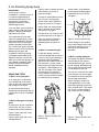
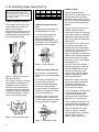
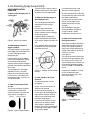
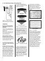
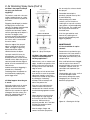
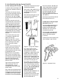
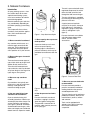
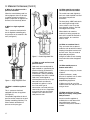
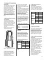
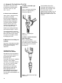
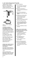
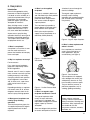
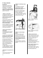
ABC’s of Spray Finishing
$10.00
1-239-C
11/01
ABC’s of Spray Finishing
Forward
While this book examines the
spray finishing operation and its
equipment from many viewpoints,
there is still much more to be
learned to become truly proficient
at spray finishing.
The best way to become proficient
at spray finishing is to just do it!
Many trade technical and
community colleges offer courses
in spray finishing, a great way to
improve your skills.
Many of the “tricks” of the
professional spray finisher involve
paints and coatings. The
manufacturers of these materials
routinely publish complete books
on these subjects. These
publications are available in
specialty paint stores and will
provide you with considerable
detail. Many of these books also
contain information on techniques
for surface preparation.
Another important source of
information, particularly on
equipment use and selection is
your local spray finishing
equipment distributor. No book
could ever completely cover a
specialist’s in-depth knowledge of
equipment, techniques,
maintenance and troubleshooting.
Information is available from many
resources on the subject of spray
finishing. It is our hope that this
book will provide you with a start
toward perfecting your finishing
skills.
Table of Contents
About this book.....
This book has been updated
several times from “The ABC’s of
Spray Equipment,” originally
published by The DeVilbiss
Company in 1954. It focuses on
equipment and techniques for
spray finishing.
Forward..........................................2
1. Introduction..............................3
Surface Preparation ..................3
Paint Preparation ......................3
2. Air Atomizing Spray Guns ......4
The format of the original book was
question-and-answer. We have
retained that format in this edition.
Spray Gun Types ......................4
This book is organized around the
major components of an air spray
system… spray guns, material
containers, hose, air control
equipment, compressors, spray
booths, respirators and a short
section on general cleanliness and
other sources of information. A
thorough understanding of the
material in this book - plus a lot of
actual spray painting practice should enable you to handle just
about any spray painting situation.
Operation...................................9
Although we have made an effort
to make this book as detailed and
as complete as possible, be aware
that the equipment and product
systems used to illustrate points
are entirely based on DeVilbiss
technology. DeVilbiss is the world’s
oldest and largest manufacturer of
spray painting equipment, and has
maintained this leadership since its
founding in 1888.
Part Identification and
Function.....................................6
Maintenance ...........................11
Troubleshooting ......................13
3. Material Containers ..............16
4. Hose and Connections.........18
5. Air Control Equipment..........20
6. Respirators.............................22
7. Air Compressors ...................23
8. Spray Booths .........................25
A recent addition to resources
available to the spray finisher is
the World Wide Web. Many
manufactures are represented and
question and answer forums are
available. Please visit our website
at www.devilbiss.com.
2
1. Introduction
This book is about the selection,
use and maintenance of finishing
equipment: spray guns, tanks,
cups, hoses, compressors,
regulators, spray booths,
respirators, etc. It presumes that
you are familiar with standard
surface preparation techniques that
may be required before finishing
actually begins. It also presumes a
basic knowledge of the many
different types of paints and
coatings available.
Creating a perfect finish requires a
solid knowledge of surface
preparation, finishes and spray
painting equipment. The first two
are extensively covered in many
other books. The manufacturers of
paints and coatings have gone to
great length to publish information
on their new and existing products.
But, even an extensive knowledge
of surface preparation techniques
and paint chemistry is not enough
to assure a professional finish. The
finish must be applied by a spray
gun, and all the variables of its use
must be mastered.
The equipment necessary to apply
the finish – the spray gun, tank,
cup, regulator, hoses, compressor,
etc. – must all be matched to the
job as well as to each other. That
equipment must be used and
maintained properly, with an
appreciation of how and why it
works the way it does.
The moment of truth for any finish
happens when the trigger is pulled.
This book focuses on that moment.
Surface Preparation
The surface to be finished should
be well cleaned before painting. If
the paint manufacturer’s
instructions call for it, the surface
should be chemically treated. Use
a blow-off gun and tack rag to
remove all dust and dirt. No
amount of primer or paint will cover
up a badly prepared surface.
3
Plastic parts may contain static
electricity from the molding
process. This static attracts
particles of dust and dirt. Eliminate
them by treating with “destatisizing” air using a special blow-off
gun that imparts a neutral charge
to the airflow. A chemical anti-static
treatment is also available.
Paint Preparation
Today’s finishes are extremely
complex chemical formulations.
They include both solvent and
waterborne types. Some may
require the addition of solvents to
form the proper spraying viscosity.
Others may simply require the
addition of a second component at
a prescribed ratio to obtain
sprayable consistency. Many of
them also have hardeners or other
chemicals, added to them to insure
correct color match, gloss,
hardness, drying time or other
characteristics necessary to
produce a first class finish. Make
sure you are familiar with the
specific finish material data sheets
accompanying each material. Do
not mix materials from various
manufacturers. Read and follow
directions carefully.
All finish materials must also be
supplied with a Material Safety
Data Sheet (MSDS). This data
provides information on proper
handling and disposal of materials.
Many states require that MSDS be
kept on file by the user.
The first step is knowing the type
and color of paint the project
requires. With this determined,
follow the manufacturer’s
instruction for preparing it exactly.
If you have any doubts about how
to proceed, don’t guess! Contact
your paint supplier for help.
Improperly prepared paint will
never produce a good finish!
The chief characteristic that
determines the sprayablility of paint
and how much film may be applied
is its viscosity … or consistency.
Following the paint manufacturer’s
instructions will get you close, but
for professional results, use a
viscosity cup. It is a simple but very
accurate way to measure the
thickness of paint. With the cup,
you can thin or reduce the paint to
the precise consistency required by
the manufacturer.
Always prepare paint in a clean,
dust-free environment. Paint has a
remarkable ability to pick up dirt.
Dirty paint will not only clog your
spray gun, but it will also ruin your
paint job. Get in the habit of always
pouring paint into the cup or tank
through a paint strainer. Paint is
never as clean as it looks.
2. Air Atomizing Spray Guns
Introduction
The spray gun is the key
component in a finishing system. It
is a precision engineered and
manufactured instrument. Each
type and size is specifically
designed to perform a certain,
defined range of tasks.
As in most other areas of finishing
work, having the right tool for the
job goes a long way toward getting professional results.
This chapter will help you know
which is the proper gun by reviewing the Conventional Air and High
Volume/Low Pressure spray gun
designs commonly used in finishing – suction feed, gravity feed and
pressure feed. It will also review the
different types of guns and
components within each design.
A thorough understanding of the
differences between systems will
allow you to select the right gun, to
use it properly to produce a high
quality finish and to contribute
toward a profitable finishing
operation.
SPRAY GUN TYPES
1. What is an air spray gun?
Figure 4 shows a material container
some distance away from its
pressure feed gun.
The type of material feed system is
also a way of classifying guns:
Suction feed is easily identified
by the fluid tip extending slightly
beyond the face of the air cap,
see figure 2.
Suction Feed...draws material to
the gun by suction as in Figure 1.
Gravity Feed...the material travels
down, carried by its own weight
and gravity as in Figure 3.
Pressure Feed...the material is fed
by positive pressure as in Figure 4.
Guns may also be classified as
either external or internal mix
depending upon the type of air
cap.
3. What is a suction feed gun?
A spray gun design in which a
stream of compressed air creates a
vacuum at the air cap, providing a
siphoning action. Atmospheric
pressure on the material in the suction cup forces it up the suction
tube, into the gun and out the fluid
tip, where it is atomized by the air
cap. The vent holes in the cup lid
must be open. This type gun is
usually limited to a one-quart, or
smaller, capacity container and low
to medium viscosity materials.
An air spray gun is a tool which
uses compressed air to atomize
paint, or other sprayable material,
and to apply it to a surface.
Figure 2 - Suction Feed Air Cap
Suction feed guns are suited to
many color changes and to small
amounts of material, such as in
touchup or lower production
operations.
4. What is a gravity feed gun?
This design uses gravity to flow the
material from the cup, which is
mounted above the gun, into the
gun for spraying. No fluid pick-up
tube is used, since the fluid outlet
is at the bottom of the cup.
This cup has a vent hole at the top
of the cup that must remain open.
It is limited to 32 ounce capacities
due to weight and balance.
Gravity feed guns are ideal for
small applications such as spot
repair, detail finishing or for finishing in a limited space. They require
less air than a suction feed gun,
and usually have less overspray.
Air and material enter the gun
through separate passages and are
mixed at the air cap in a controlled
pattern.
2. What are the types of air spray
guns?
Air spray guns may be classified in
various ways. One way is by the
location of the material container:
Figure 1 shows a gun with a cup
attached below it.
Figure 3 shows a gun with a cup
attached above it.
Figure 1- Suction Feed Gun with
attached cup
Figure 3 - Gravity Feed Gun with
attached cup
4
2. Air Atomizing Spray Guns (Cont’d)
A DeVilbiss Pro Tip:
When using a gravity feed system,
downsize the tip one size from suction.
If the suction system calls for a .070",
use a .055" or .063"
Type
Feed
Viscosity
(#2 Zahn)
Fluid
Oz/Minute
Atomizing
Pressure
Type
Production
Suction
up to 24
10-12
40-50
Low
Gravity
up to 24
10-12
30-50
Low
Pressure
up to 29
30-Oct
50-60
High
HVLP
up to 29
14-16
10
High
Table 1
5. What is a pressure feed gun?
In this design, the fluid tip is flush
with the face of the air cap (see
Figure 5). The material is
pressurized in a separate cup, tank
or pump. The pressure forces the
material through the fluid tip and to
the air cap for atomization.
6. What is an external mix air
cap?
This gun mixes and atomizes air
and fluid outside the air cap.
It can be used for applying all
types of materials, and it is
particularly desirable when
spraying fast drying paints such
as lacquer. It is also used when a
high quality finish is desired.
Figure 6 - External Mix Gun
7. What is an internal mix cap?
Figure 4 - Typical Pressure Feed
Gun with remote pot
This system is normally used when
large quantities of material are to
be applied, when the material is
too heavy to be siphoned from a
container or when fast application
is required. Production spraying in
a manufacturing plant is a typical
use of a pressure feed system.
This cap mixes air and material
inside the air cap, before expelling
them.
It is normally used where low air
pressures and volumes are
available, or where slow-drying
materials are being sprayed.
A typical example is spraying flat
wall paint, or outside house paint,
with a small compressor.
Internal mix caps are rarely used
for finishing when a fast-drying
material is being sprayed, or when
a high quality finish is required.
HVLP, or High-Volume/Low
Pressure, uses a high volume of air
(typically between 10-26 CFM)
delivered at low pressure (10 PSI or
less at the air cap) to atomize paint
into a soft, low-velocity pattern of
particles.
In many cases, less than 10 psi is
needed in order to atomize.
Proper setup utilizes no more fluid
and air pressure than is needed to
produce the required quality and a
flow rate that will meet production
requirements.
As a result, far less material is lost
in overspray, bounceback and
blowback than with conventional
air spray. This is why HVLP delivers
a dramatically higher transfer
efficiency (the amount of paint that
adheres to the substrate compared
to the amount of paint sprayed)
than spray systems using a higher
atomizing pressure.
The HVLP spray gun resembles a
standard spray gun in shape and
operation. Models that use high
inlet pressure (20-80 psi) and
convert to low pressure internally
within the spray gun are called
HVLP conversion guns.
Some HVLP models, particularly
those using turbines to generate
air, bleed air continuously to
minimize back-pressure against
the air flow of the turbine.
The air cap design is similar to that
of a standard spray gun, with a
variety of air jets directing the
atomizing air into the fluid stream,
atomizing it as it leaves the tip.
HVLP is growing in popularity and
new environmental regulations are
requiring it for many applications.
HVLP can be used with a wide
variety of materials, including
two-component paints, urethanes,
acrylics, epoxies, enamels,
lacquers, stains, primers, etc.
Figure 5 - Pressure Feed Air Cap
Figure 7 - Internal Mix Air Cap
5
8. What is HVLP?
2. Air Atomizing Spray Guns (Cont’d)
PART IDENTIFICATION
FUNCTION
9. What are the principal parts of
a spray gun?
There are various styles of caps to
produce different sizes and shapes
of patterns for many applications.
12. What are the advantages of
the multiple jet cap?
This cap design provides better
atomization of more viscous
materials.
It allows higher atomization
pressures to be used on more
viscous materials with less danger
of split spray pattern.
Figure 8 - Spray Gun Anatomy
It provides greater uniformity in
pattern due to better equalization
of air volume and pressure from the
cap.
10. What happens when the
trigger is pulled?
It also provides better atomization
for materials that can be sprayed
with lower pressures.
The trigger operates in two stages.
Initial trigger movement opens the
air valve, allowing air to flow
through the gun.
11. What is the function of the
air cap?
The air cap (see figure 10) directs
compressed air into the fluid
stream to atomize it and form the
spray pattern. (see Figure 9)
Round
Tapered
Blunt
Figure 9 - Types of Spray Patterns
d) size of fluid tip to be used (most
air caps work best with certain fluid
tip/needle combinations)
e) volume of air in cubic feet per
minute (cfm) and pressure in
pounds per square inch (psi)
available.
See the DeVilbiss spray gun
catalog for proper selection of
air cap / fluid tip / needle
combinations and typical uses.
14. What is the function of the
fluid tip and needle?
They restrict and direct the flow of
material from the gun into the air
stream. The fluid tip includes an
internal seat for the tapered fluid
needle, which reduces the flow of
material as it closes.
(see Figure 11).
The amount of material that leaves
the front of the gun depends upon
the viscosity of the material, the
material fluid pressure and the size
of the fluid tip opening provided
when the needle is unseated from
the tip.
Further movement of the trigger
pulls the fluid needle from its seat
at the fluid tip, allowing fluid
material to flow. When the trigger is
released, the fluid flow stops before
the air flow.
This lead/lag time in the trigger
operation assures a full spray
pattern when the fluid flow starts.
It also assures a full pattern until
the fluid flow stops, so there is no
coarse atomization.
c) material feed system used
(pressure, suction or gravity)
Figure 10 - Multiple Jet External Mix
Air Cap
13. How should an air cap be
selected?
Fluid tips are available in a variety
of sizes to properly handle
materials of various types, flow
rates and viscosity.
The following factors must be
considered:
a) type, viscosity and volume of
material to be sprayed
b) size and nature of object, or
surface to be sprayed (multiple, or
larger, orifices increase ability to
atomize more material for faster
painting of large objects).
Fewer, or smaller orifices usually
require less air, produce smaller
spray patterns and deliver less
material. (These caps are designed
for painting smaller objects and/or
using slower speeds)
Figure 11 - The Fluid Tip and
Needle
6
2. Air Atomizing Spray Guns (Cont’d)
15. What is the nozzle
combination?
Rule of thumb
Rule of thumb
Optimum fluid pressures are 8-20
psi. Pressures greater than this
generally indicate the need for a
larger fluid tip size.
The lower the viscosity of the
material, the smaller the I.D. of
the fluid tip.
In practice, the air cap, fluid tip,
needle and baffle are selected as a
unit, since they all work together to
produce the quality of the spray
pattern and finish. These four
items, as a unit, are referred to as
the nozzle combination.
17. How are fluid tip and needle
sizes identified?
16. What are standard fluid tip
sizes and flow rates?
DeVilbiss fluid tips and needles are
identified by the letters stamped on
the tip and the needle.
The standard sizes, corresponding
fluid tip opening dimensions and
flow rates are:
Conventional Air Spray
Tip
ID
Flow Rate
Pressure Feed Systems
G
.028"/.7mm
up to 12 oz/min
FX
.0425"/1.1mm up to 20 oz/min
FF
.055"/1.4mm
up to 30 oz/min
E
.070"/1.8mm
over 30 oz/min
EE
.070"/1.8mm
porcelain enamel
D
.086"/2.2mm
heavy body mtls
AC
.110"/2.75mm heavy body mtls
Suction Feed Systems
EX
.070"/1.8mm
up to 12 oz/min
FW
.062"/1.6mm
up to 10 oz/min
Gravity Feed Systems
FF
.055"/1.4mm
up to 30 oz/min
FW
.062"/1.6mm
up to 30 oz/min
Table 2
HVLP
Tip
ID
Flow Rate
Pressure Feed Systems
FX
.0425"/1.1mm up to 10 oz/min
FF
.055"/1.4mm
up to 14 oz/min
E
.070"/1.8mm
up to 20 oz/min
D
.086"/2.2mm
over 20 oz/min
Suction Feed Systems
D
.086"/2.2mm
up to 9 oz/min
DE
.070"/1.8mm
up to 8 oz/min
Gravity Feed Systems
FF
.055"/1.4mm
up to 12 oz/min
FW
.062"/1.6mm
up to 12 oz/min
Table 3
7
The identification letters on these
components should match. See
the appropriate DeVilbiss spray gun
catalog for the proper selection of
fluid tip and needle combinations.
18. What fluid tip and needle
combination sizes are most
common?
E, EX, FF and FX are most
generally used. The EX
combination is used for suction
feed, while FF and FW are used for
gravity Feed. For pressure feed the
most common tips are FX, FF
and E.
19. How are nozzle combinations
selected?
Five basic considerations are
involved in selecting the nozzle
com-bination:
•
type and viscosity of material
being sprayed
•
physical size of object being
finished/fan pattern size
•
desired speed/finish quality
•
gun model being used
•
available air volume (cfm) and
pressure (psi) from compressor
(1) The type and viscosity of the
material being sprayed is the
first factor to consider.
Material
Viscosity
#2 Zahn
Production
Rate
up to 23 sec
23-28 sec
28-48 sec
over 48 sec
Low
Med
High
High
Tip
Size
FX(.042)
FF(.055)
E(.070)
D(.086)
Table 4
NOTE: Viscosity conversion charts
are available to convert one
viscosity cup reading to another
from any material or equipment
supplier.
(2) The physical size of the object
to be painted must also be
considered. As a general rule, use
the largest possible spray pattern
consistent with the object size.
Remember that different air caps
deliver various pattern characteristics. This can reduce both spraying
time and the number of gun
passes.
(3) The next consideration in
evaluating nozzle combinations is
the speed with which the finish will
be applied and the desired level of
quality.
For speed and coverage, choose a
nozzle combination which
produces a pattern as wide as
possible.
When quality is the deciding factor,
choose a nozzle combination
which produces fine atomization
and a smaller pattern size, thereby
giving greater application control.
(4) The model of the gun itself will
limit the selection of nozzle
combination.
For a DeVilbiss suction feed gun,
there are several nozzle types
available which are suitable for
finishing operations. These nozzles
2. Air Atomizing Spray Guns (Cont’d)
have fluid tip openings ranging
from .062" to.086", and are
designed to handle viscosities up
to 28 seconds in a No. 2 Zahn
Viscosity Cup.
For a DeVilbiss pressure feed gun,
the amount of material discharged
depends upon material viscosity,
inside diameter of the fluid tip,
length and size of hose, and
pressure on the material container
or pump.
If the fluid tip opening is too small,
the paint stream velocity will be too
high. If the fluid tip opening is too
large, you will lose control over the
material discharging from the gun.
For most HVLP guns, the paint
flow shouldn't exceed 16 oz. per
minute. For higher flow rates,
consult the DeVilbiss HVLP Spray
Gun catalog.
(5) Available air supply is the last
factor to consider.
air cap, will not be able to atomize
it properly causing a center-heavy
pattern.
If the fluid tip opening is too large,
material discharge control will
be lost.
The fluid tip/air cap combination
must be matched to each other
and to the job at hand. Spray gun
catalogs include charts to help
you match them properly.
21. Of what metals are fluid tips
made?
Tips are made of the following
metals:
a) 300-400 grade stainless steel for
both non-corrosive and corrosive
materials
c) Carboloy inserts for extremely
abrasive materials
Pressure feed air caps consume
between 7.0 and 25.0 CFM,
depending on design. If your air
supply is limited, because of an
undersize compressor, or many
other air tools are in use at once,
the gun will be starved for air,
producing incomplete atomization
and a poor finish.
22. What is viscosity?
20. What are the criteria for
selecting a pressure feed nozzle?
The most common measurement
used to determine viscosity in
finishing is flow rate (measured in
seconds from a Zahn, Ford, Fisher
or other viscosity cup).
While the fluid discharge in ounces
per minute from a suction feed gun
is relatively stable (largely because
it is determined by atmospheric
pressure), the fluid discharge from
a pressure feed gun depends more
upon the size of the inside
diameter of the fluid tip and the
pressure on the paint container or
pump. The larger the opening, the
more fluid is discharged at a given
pressure.
If the fluid tip ID is too small for the
amount of material flowing from the
gun, the discharge velocity will be
too high. The air, coming from the
The viscosity of a liquid is its body,
or thickness, and it is a measure
of its internal resistance to flow.
Viscosity varies with the type and
temperature of the liquid. Any
reference to a specific viscosity
measurement must be
accompanied by a corresponding
temperature specification.
Different viscosity cup sizes are
available. Each cup has a hole at
the bottom, specified to an exact
size. Use a viscosity cup that is
designed to handle the time range
of the materials in use. Viscosity
control is an extremely important
and effective method to maintain
application efficiency and quality
consistency. Always measure
viscosity after each batch of
material is mixed and make sure
material temperature is the same,
normally 70° to 80° F.
Viscosity recommendations may
be given in poise and centipoise
(1 poise=100 centipoise). Viscosity
conversion may be accomplished
by consulting a viscosity
conversion chart.
23. What is the spreader adjustment valve?
A valve for controlling the air to the
horn holes which regulate the spray
pattern from maximum width down
to a narrow or round pattern
(see figure 8).
24. What is the fluid needle
adjustment?
This adjustment controls the
distance the fluid needle is allowed
to retract from its seat in the fluid
tip, which allows more or less
material through the fluid tip
(see figure 14).
With pressure feed systems, the
fluid delivery rate should be
adjusted by varying the fluid
pressure at the pressure pot. Use
the fluid adjustment knob for minor
and/or temporary flow control. This
will extend the life of the fluid
needle and tip.
25. What are the components of
suction and gravity feed
systems?
Typical suction and gravity feed
systems consist of: a suction feed
or gravity feed spray gun with cup,
an air compressor (not shown), a
combination filter/air regulator and
air hoses (see figure 12).
8
2. Air Atomizing Spray Guns (Cont’d)
the Troubleshooting Section for
examples of faulty patterns to help
diagnose your problem.
(4) If the paint is not atomizing
properly, increase the air pressure
slightly and make another test
pass. Continue this sequence until
the paint particle size is relatively
uniform.
Uneven Distribution
Figure 12 – Suction Feed and
Gravity Feed System Components
OPERATION
26. How is suction and gravity
feed equipment hooked up for
operation?
Connect the air supply from the
compressor outlet to the filter/air
regulator inlet.
Connect the air supply hose from
the air regulator outlet to the air
inlet on the spray gun.
After the material has been
reduced to proper consistency,
thoroughly mixed and strained into
the cup, attach the gun to the cup
(suction feed) or pour material into
attached cup (gravity feed).
Figure 13 - Horizontal Test Pattern
(2) If the pattern produced by the
above test appears normal, rotate
the air cap back to a normal
spraying position and begin spraying. (Example - a normal pattern
with a #30 air cap will be about 9"
long when the gun is held 8" from
the surface).
Figure 15- Test Patterns
(5) If the pattern seems starved for
material, and the fluid adjustment
screw allows full needle travel, the
fluid tip may be too small or the
mater-ial may be too heavy.
Recheck the viscosity or increase
the size of the fluid tip and needle
(6) If the material is spraying too
heavily and sagging, reduce the
material flow by turning in the fluid
adjusting screw (clockwise).
27. How are suction and gravity
feed systems initially adjusted for
spraying?
Figure 14 – Fluid Adjustment Screw
(1) Spray a horizontal test pattern
(air cap horns in a vertical position).
Hold the trigger open until the paint
begins to run. There should be
relatively even distribution of the
paint across the full width of the
pattern. (see Figure 13). Adjust the
pattern width with the spreader
adjustment valve. If distribution is
not even, there is a problem with
either the air cap or the fluid tip
that must be corrected. Refer to
(3) With the fluid adjusting screw
open to the first thread,(see figure
14) and the air pressure set at
approximately 30 psi, make a test
pass (move the spray gun 3 times
the normal speed) with the gun on
some clean paper, cardboard or
wood. If there are variations in
particle size- specks and/or large
globs - the paint is not atomizing
properly (see figure 15).
9
Even Distribution
Remember, proper setup utilizes no
more fluid and air pressure than is
needed to produce the required
quality and a flow rate that will
meet production requirements.
2. Air Atomizing Spray Guns (Cont’d)
28. What are the components of
a pressure feed system?
A pressure feed system consists of:
a pressure feed spray gun, a pressure feed tank, cup or pump, an air
filter/regulator, appropriate air and
fluid hoses, and an air com-pressor
(see figure 16).
Open fluid adjustment screw until
the first thread is visible (see
figure 14).
31. How is the pressure feed
gun balanced for spraying?
1) Using control knob on fluid
regulator, set fluid pressure at
5 to 10 psi.
2) Using control knob on air
regulator, set air atomization
pressure at 25-35 psi.
3) Spray a test pattern (fast pass)
on a piece of paper, cardboard, or
wood. From that test pattern,
determine if the particle size is
small enough and relatively uniform
throughout the pattern to achieve
the required finish quality (see
figure 15). If particle size is too
large or is giving too much texture
in the finish, turn the atomization
pressure up in 3 to 5 psi
increments until particle size and
texture of finish is acceptable.
Figure 16 - Pressure Feed System
Components
29. How is equipment hooked up
for pressure feed spraying?
Connect the air hose from the air
regulator to the air inlet on the gun.
Connect the mainline air hose to
the air inlet on the tank. CAUTION:
Do not exceed the container's
maximum working pressure.
Connect the fluid hose from the
fluid outlet on the tank to the fluid
inlet on the gun.
30. How is the pressure feed gun
adjusted for spraying?
Open spreader adjustment valve
for maximum pattern size (see
figure 8).
4) Spray a part with these settings.
If you are not able to keep up with
the production rate required or if
the finish is starved for material,
increase the fluid pressure with the
fluid regulator control knob in 2 to
4 psi increments until required wet
coverage is accomplished.
Note: A larger capacity fluid tip
may be required.
5) Remember, as you turn up the
fluid pressure the particle size will
increase. Once the coverage
required is obtained, it will be
necessary to re-adjust the
atomization pressure in 3 to 5 psi
increments as explained in step 3
to insure required particle size and
finish texture is achieved.
6) If using HVLP, using an “Air Cap
Test Kit”, verify that the air cap
pressure in not above 10 psi if
required by a regulatory agency.
Figure 17 – Air Cap Test Kit
After establishing the operating
pressures required for production
and finish quality, develop a
Pressure Standardization program
for your finish room to follow.
32. What is a Pressure
Standardization Program?
After establishing air and fluid
pressures that meet required quality and production, record the data
to be used for that application for
future reference. (see figure 18)
Booth #: _______________
Material Sprayed ________
Application _____________
Viscosity _______________
Fluid Temperature ________
Spray Gun ______________
Air Cap ______ Fluid Tip ___
Air Pressure _____________
Fluid Pressure ____________
Figure 18 – Pressure
Standardization Chart
33. How should the spray gun be
held?
It should be held so the pattern is
perpendicular to the surface at all
times.
Keep the gun tip 8-10 inches (air
spray guns) or 6-8 inches (HVLP
guns) from the surface being
sprayed.
10
2. Air Atomizing Spray Guns (Cont’d)
34. What is the proper technique
for spray gun stroke and
triggering?
flat, or nearly flat, surfaces should
be sprayed.
Remember to overlap the
previously sprayed areas by 50%
to avoid streaking.
The stroke is made with a free arm
motion, keeping the gun at a right
angle to the surface at all points of
the stroke.
When painting very narrow
surfaces, you can switch to a
smaller gun, or cap with a smaller
spray pattern, to avoid readjusting
the full size gun. The smaller guns
are usually easier to handle in
restricted areas.
Triggering should begin just before
the edge of the surface to be
sprayed. The trigger should be held
fully depressed, and the gun
moved in one continuous motion,
until the other edge of the object is
reached. The trigger is then
released, shutting off the fluid flow,
but the motion is continued for a
few inches until it is reversed for
the return stroke.
When the edge of the sprayed
object is reached on the return
stroke, the trigger is again fully
depressed and the motion
continued across the object.
Lap each stroke 50% over the
preceding one. Less than 50%
overlap will result in streaks on the
finished surface. Move the gun at a
constant speed while the trigger is
pulled, since the material flows at a
constant rate.
Another technique of triggering is
referred to as “feathering.”
Feathering allows the operator to
limit fluid flow by applying only
partial trigger travel.
35. What happens when the gun
is arced?
Arcing the stroke results in uneven
application and excessive overspray at each end of the stroke.
When the tip is arced at an angle of
45 degrees from the surface (see
figure 19), approximately 65% of
the sprayed material is lost.
A full size gun could be used,
however, by reducing the air
pressure and fluid delivery and
trigger-ing properly.
MAINTENANCE
37. How should the air cap be
cleaned?
Figure 19 - Spray Techniques
36. What is the proper spraying
sequence and technique for
finishing applications?
Difficult areas, such as corners and
edges, should be sprayed first. Aim
directly at the area so that half of
the spray covers each side of the
edge or corner.
Hold the gun an inch or two closer
than normal, or screw the spreader
adjustment control in a few turns.
Needle travel should be only partial
by utilizing the “feathering”
technique. Either technique will
reduce the pattern size.
If the small holes become clogged,
soak the cap in clean solvent. If
reaming the holes is necessary, use
a toothpick, a broom straw, or
some other soft implement (see
figure 20).
Cleaning holes with a wire, a nail or
a similar hard object could
permanently damage the cap by
enlarging the jets, resulting in a
defective spray pattern.
If the gun is just held closer, the
stroke will have to be faster to
compensate for a normal amount
of material being applied to smaller
areas.
When spraying a curved surface,
keep the gun at a right angle to
that surface at all times. Follow
the curve. While not always
physically possible, this is the ideal
technique to produce a better,
more uniform, finish.
After the edges, flanges and
corners have been sprayed, the
11
Remove the air cap from the gun
and immerse it in clean solvent. If
necessary, use a bristle brush to
clean dried paint. Blow it dry with
compressed air.
Figure 20 - Cleaning the Air Cap
2. Air Atomizing Spray Guns (Cont’d)
38. How should guns be cleaned?
A suction or pressure feed gun with
attached cup should be cleaned as
follows:
Turn off the air to the gun, loosen
the cup cover and remove the fluid
tube from the paint. Holding the
tube over the cup, pull the trigger
to allow the paint to drain back into
the cup.
The solvent is contained, and must
be disposed of properly.
Some states’ codes require the use
of a gun cleaner, and it is un-lawful
to discharge solvent into the
atmosphere.
After cleaning a spray gun in a gun
cleaner, be sure to lubricate as
indicated in Figure 22.
Empty the cup and wash it with
clean solvent and a clean cloth. Fill
it halfway with clean solvent and
spray it through the gun to flush
out the fluid passages by directing
stream into an approved, closed
container. All containers used to
transfer flammable materials should
be grounded. (Be sure to comply
with local codes regarding solvent
disposal).
The fluid needle packing A, the air
valve packing B and the trigger
bearing screw C require daily
lubrication with a non-silicone/
non-petroleum gun lube.
The fluid needle spring D should
be coated lightly with petroleum
jelly or a non-silicone grease
(ie. Lithium).
Lubricate each of these points after
every cleaning in a gun washer!
Wipe off the gun with a solventsoaked rag, or if necessary, brush
the air cap and gun with a fiber
brush using clean-up liquid
or thinner.
Material in hoses may be blown
back. The lid must be loose and
fluid pressure off. Keep gun higher
than container, loosen air cap and
trigger gun until atomizing air
forces all material back into the
pressure vessel.
A gun cleaner may be used for
either type of gun. This is an
enclosed box-like structure
(vented) with an array of cleaning
nozzles inside.
Guns and cups are placed over the
nozzles, the lid is closed, the valve
is energized, and the pneumatically
controlled solvent sprays through
the nozzles to clean the equipment.
Clean the air cap, fluid tip and tank.
Reassemble for future use.
39. What parts of the gun require
lubrication? (Figure 22)
Then, remove the air cap, clean
it as previously explained, and
replace it on the gun.
To clean a pressure feed gun with
remote cup or tank, turn off air
sup-ply to cup or tank. Release
materi-al pressure from the system
by opening relief valve.
Clean the container and add clean
solvent. Atomization air should be
turned off during this procedure.
Pressurize the system and run
the solvent through until clean.
(Be sure to comply with local
codes regarding solvent dispersion
and disposal.)
Figure 21 - Using a Hose Cleaner
Use a hose cleaner to clean
internal passages of spray guns
and fluid hose. This device
incorporates a highly efficient fluid
header, which meters a precise
solvent/air mixture. The cleaner
operates with compressed air and
sends a finely - atomized blast of
solvent through the fluid passages
of the hose, the spray gun, etc.
This simple, easy to use cleaner
speeds up equipment cleaning and
saves solvent. Savings may be as
much as 80%. It also reduces VOC
emissions. (Be sure that both the
hose cleaner and gun are
properly grounded.)
Figure 22 - Lubrication Points
Where local codes prohibit the use
of a hose cleaner, manually
backflush the hose into the cup or
tank with solvent until clean and
dry with compressed air.
12
2. Air Atomizing Spray Guns (Cont’d)
Problem
Cause
Correction
Fluid leaking from packing nut
1. Packing nut loose
2. Packing worn or dry
1. Tighten, do not bind needle
2. Replace or lubricate
Air leaking from front of gun
1. Sticking air valve stem
2. Foreign matter on air valve
or seat
3. Worn or damaged air valve
or seat
4. Broken air valve spring
5. Bent valve stem
6. Air valve gasket damaged
or missing
1. Lubricate
2. Clean
1. Dry packing
2. Packing nut too tight
3. Fluid tip or needle worn
or damaged
4. Foreign matter in tip
5. Fluid needle spring broken
6. Wrong size needle or tip
1. Lubricate
2. Adjust
3. Replace tip and needle with
lapped set
4. Clean
5. Replace
6. Replace
Fluid leaking or dripping from
front of pressure feed gun
3. Replace
4. Replace
5. Replace
6. Replace
All Feed Systems
Jerky, fluttering spray
1. Loose or damaged fluid
tip/seat
2. Dry packing or loose fluid
needle packing nut
3. Material level too low
4. Container tipped too far
5. Obstruction in fluid passage
6. Loose or broken fluid tube
or fluid inlet nipple
1. Tighten or replace
2. Lubricate packing or tighten
packing nut
3. Refill
4. Hold more upright
5. Backflush with solvent
6. Tighten or replace
Suction Feed Only
7. Material too heavy
8. Air vent clogged
9. Loose, damaged or dirty lid
10. Fluid tube resting on cup
bottom
11. Damaged gasket behind
fluid tip
13
7. Thin or reduce
8. Clear vent passage
9. Tighten, replace or clean
coupling nut
10. Tighten or shorten
11. Replace gasket
2. Air Atomizing Spray Guns (Cont’d)
Problem
Cause
Correction
Top or bottom-heavy spray
pattern*
1. Horn holes plugged
1. Clean, ream with non-metallic
point (ie. toothpick)
2. Clean
2. Obstruction on top or bottom
of fluid tip
3. Cap and/or tip seat dirty
Right or left-heavy spray
pattern*
1. Horn holes plugged
2. Dirt on left or right side of
fluid tip
3. Clean
1. Clean, ream with non-metallic
point (ie. toothpick)
2. Clean
*Remedies for the top, bottom,
right, left heavy patterns are:
1. Determine if the obstruction is on
the air cap or fluid tip. Do this by
making a solid test spray pattern.
Then, rotate the cap one-half turn
and spray another pattern. If the
defect is inverted, obstruction is on
the air cap. Clean the air cap as
previously instructed.
2. If the defect is not inverted, it is on
the fluid tip. Check for a fine burr
on the edge of the fluid tip.
Remove with #600 wet or dry sand
paper.
3. Check for dried paint just inside the
opening. Remove paint by washing
with solvent.
Center-heavy spray pattern
Split spray pattern
1. Fluid pressure too high for
atomization air (pressure feed)
2. Material flow exceeds air
cap’s capacity
3. Spreader adjustment valve set
too low
4. Atomizing pressure too low
5. Material too thick
1. Balance air and fluid pressure
Increase spray pattern width
2. Thin or reduce fluid flow
1. Fluid adjusting knob turned
in too far
2. Atomization air pressure too
high
3. Fluid pressure too low
(pressure feed)
4. Fluid tip too small
1. Back out counter-clockwise to
increase flow
2. Reduce at regulator
3. Adjust
4. Increase pressure
5. Thin to proper consistency
3. Increase fluid pressure
4. Change to larger tip
14
2. Air Atomizing Spray Guns (Cont’d)
Problem
Cause
Starved spray pattern
1. Inadequate material flow
2. Low atomization air pressure
(suction feed)
Correction
1. Back fluid adjusting screw
out to first thread or increase
fluid pressure
2. Increase air pressure and
rebalance gun
Unable to form round
spray pattern
1. Fan adjustment stem not
seating properly
1. Clean or replace
Dry spray
1. Air pressure too high
2. Material not properly reduced
(suction feed)
3. Gun too far from surface
4. Gun motion too fast
1. Lower air pressure
2. Reduce to proper consistency
and temperature
3. Adjust to proper distance
4. Slow down
Excessive overspray
1. Too much atomization air
pressure
2. Gun too far from surface
3. Improper technique (arcing,
gun speed too fast)
1. Reduce pressure
Excessive fog
1. Too much, or too fast-drying
thinner
2. Too much atomization air
pressure
1. Remix with proper reducer
and temperature
2. Reduce pressure
Will not spray
1. Pressure feed cap/tip used
with suction feed
2. No pressure at gun
3. Fluid needle not retracting
4. Fluid too heavy (suction feed)
1. Use suction feed cap/tip
15
2. Use proper gun distance
3. Use moderate pace, keeping
gun parallel to work surface
2. Check air lines
3. Open fluid adjusting screw
4. Lower fluid viscosity or
change to pressure feed
3. Material Containers
Introduction
The tank is pressurized with clean,
regulated, compressed air, which
forces the fluid out of the tank
through the fluid hose to the gun.
All spray painting systems - from
the smallest brush to the most
sophisticated finishing systemmust have containers to hold the
material being applied.
The rate of fluid flow is controlled
by increasing or decreasing the air
pressure in the tank.
Material container types and sizes
vary considerably, depending on
the kind of spraying system being
used.
This chapter will discuss these
containers, their particular applications, their construction and
maintenance.
1. What are material containers?
Any container which serves as a
material supply reservoir for the
spray gun. These containers are
usually made of metal or plastic
with capacities of 1/2 pint or more.
A
B
Figure 1 - Cup Attachment Styles
5. What capacity does a pressure
feed cup have?
A typical pressure feed tank
consists of: the shell A, clamp-on
lid B, fluid tube C, fluid outlet D,
regulator E, gauge F, safety relief
valve G, and agitator H (see
figure 3).
Pressure feed tanks are available
with either top or bottom fluid
outlets, and with various
accessories.
A pressure feed cup can have a
one or two quart capacity.
Anything larger is considered a
pressure feed tank, which may be
positioned some distance from the
gun.
2. What are the types of material
containers?
There are three common types of
cups which attach to the gun itself:
Siphon, Gravity and Pressure.
There are also remote pressure
cups and tanks, which are located
away from the gun. See Page 4 for
types of guns and systems.
Figure 3 - Pressure Feed Tank
3. Where are cup containers
used?
Cup containers are typically one
quart or less, and are used where
relatively small quantities of
material are being sprayed.
7. Where are pressure feed tanks
recommended?
Figure 2 - Regulated 2 Qt. Pressure
Cup
4. How are material feed cups
attached to lid assemblies?
6. How do pressure feed tanks
work?
Cups are attached using a lid
assembly (sometimes called a cup
attachment) that either clamps A or
screws B onto the cup container.
(see Figure 1) Some lid assemblies
are detachable from the gun, while
others are integral parts and do not
detach from less expensive models.
Pressure feed tanks are closed
containers, ranging in size from
about two gallons to 60 gallons.
They provide a constant flow of
material, under constant pressure,
to the spray gun.
Pressure feed tanks provide a
practical, economical method of
feeding material to the gun over
extended periods of time.
They are mostly used in continuous
production situations, because the
material flow is positive, uniform
and constant.
Tanks can be equipped with
agitators (see Figure 3) that keep
the material mixed and in
suspension.
16
3. Material Containers (Cont’d)
8. When is an agitator used in a
pressure feed tank?
12. What materials are used to
construct pressure feed tanks?
When the material being used has
filler or pigment that must be kept
in motion to keep its particles in
proper suspension. An agitator can
be hand, air or electrically driven.
The smaller, non-code, light-duty
tanks are made of plated steel and
have lower inlet pressure
restrictions.
The heavy-duty, ASME-code tanks
are made of galvanized or 300
series stainless steel. They also
have plated or stainless steel lids
with forged steel clamps.
9. What is a single regulated
tank?
This is a pressure feed tank with
one air regulator controlling only
the pressure on the material in the
tank (see figure 4).
When abrasive or corrosive
materials are being sprayed, the
tank shell is coated or lined with a
special material, or a container
insert is used.
13. What are container liners?
They are inserts that are placed
inside the tank to hold the material,
keeping it from direct contact with
the tank walls. They are made of
disposable polyethylene.
Figure 5 - Double Regulated Tank
Using liners reduces tank cleaning
time and makes color changeover
easier.
11. What are code and non-code
pressure tanks?
Code tanks are manufactured to
rigid standards as specified by the
American Society of Mechanical
Engineers. (ASME) Each step of
manufacture is closely controlled,
and welding of the shell is certified.
Code tanks are designed to
withstand pressures up to 110 psi.
Figure 4 - Single Regulated Tank
10. What is a double regulated
tank?
This is a pressure feed tank
equipped with two air regulators
(see figure 5).
One provides regulation for the air
pressure on the material in the tank
(thereby controlling fluid flow). The
other controls atomization air
pressure to the spray gun.
17
Non-code tanks are normally
restricted to 3 gallons in size or
less. Due to the type of
construction, non-code tanks are
rated at 80 psi or less. Regulations
may restrict the type of materials
and pressures used with a noncode pressure tank.
14. When would you use a
bottom outlet tank?
1) When you are using very viscous
materials.
2) When continuous, steady
pressure is required, such as when
feeding plural component
proportioning equipment.
3) When you wish to use all the
material in the tank and you are not
using an insert.
15. What would I use if I have
difficulty accurately setting lower
fluid pressures?
An extra-sensitive regulator is
available for use with lower fluid
flow and/or lower viscosity
materials where precise control is
needed.
4. Hoses & Connections
Introduction
The various types of hose used to
carry compressed air and fluid
material to the spray gun are
important parts of the system.
Improperly selected or maintained
hose can create a number of
problems. This chapter will review
the different kinds of hose and
fittings in use, provide guidance in
selecting the proper types for the
job and cover the maintenance of
hose.
1. What types of hose are used in
spray painting?
There are two types: air hose –
used to transfer compressed air
from the air source to the gun, and
fluid hose – used only in pressure
feed systems to transfer the
material from its container to the
spray gun.
(NOTE: Do not use air hose for
solvent-based materials.)
The tube is the interior flexible
artery that carries air or fluid
material from one end of the hose
to the other.
The reinforcement adds strength to
the hose. It is located between the
tube and cover, and it can be many
combinations of materials and
reinforcement design. Its design
determines pressure rating,
flexibility, kink and stretch
resistance and coupling retention.
The cover is the outer skin of the
hose. It protects the reinforcement
from contact with oils, moisture,
solvents and abrasive objects. The
cover protects the reinforcement,
but does not contribute to hose
performance.
DeVilbiss hose is color-coded:
GREY............air w/static ground
BLACK ..........low pressure fluid
Since the solvents in coatings
would readily attack and destroy
ordinary rubber compounds, fluid
hose is lined with special solventresistant nylon material that is
impervious to common solvents.
4. What sizes of fluid hose are
recommended?
2. How is hose constructed?
DeVilbiss hose is a performance
designed combination of three
com-ponents: Tube A,
Reinforcement B and Cover C.
The hose from the regulator to a
gun or tank should be a minimum
of 5/16" ID. Tools requiring more air
may need 3/8" I.D. hose or larger.
Type
Length
Size
0' - 10'
1/4" ID
General
10' - 20'
5/16" ID
Purpose
20' - 50'
3/8" ID
50' - 100'
1/2" ID
0' to 20'
5/16" ID
20' - 50'
3/8" ID
50' - 100'
1/2" ID
HVLP
Figure 3 - Recommended air
hose sizes
RED or TAN ...........air and water
3. What type of tube is used in
fluid hose?
Figure 1 - Basic Hose Construction
5. What sizes of air hose are
recommended?
Type
Length
Size
General
0' - 20'
1/4" ID
Purpose
10' - 35'
3/8" ID
35' - 100'
1/2" ID
100' - 200'
3/4" ID
Figure 2 - Recommended fluid hose
sizes
6. What is pressure drop?
This is the loss of air pressure due
to friction (caused by air flow)
between the source of the air and
the point of use. As the air travels
through the hose or pipe, it rubs
against the walls. It loses energy,
pressure and volume as it goes.
7. How can this pressure drop be
determined?
At low pressure, with short lengths
of hose, pressure drop is not
particularly significant. As pressure
increases, and hose is lengthened,
the pressure rapidly drops and
must be adjusted.
All air hose is subject to pressure
loss or drop. For example, 1/4"
pressure drop is 1 psi per foot and
5/16" is 1/2 psi per foot. This
pressure loss may result in poor
atomization.
Too often, a tool is blamed for
malfunctioning, when the real
cause is an inadequate supply of
compressed air due to an
undersized I.D. hose.
18
4. Hoses & Connections (Cont’d)
For optimum spray gun results,
the following is recommended:
up to 20 ft - 5/16" I.D., over
20 ft - 3/8" I.D.
11. What is a threaded- type
connection?
This is a common swivel-fitting
type that is tightened with a
wrench.(see figure 4).
8. How are hoses maintained?
Hoses will last a long time if they
are properly maintained.
Be careful when dragging hose
across the floor. It should never
be pulled around sharp objects,
run over by vehicles, kinked or
otherwise abused. Hose that
ruptures in the middle of a job
can ruin or delay the work.
Proper hose cleaning techniques
are covered on Pages 11 and 12.
The outside of both air and fluid
hose should be occasionally wiped
down with solvent. At the end of
every job, they should be stored
by hanging up in coils.
9. What kinds of hose fittings are
available?
Permanent, crimp type or reusable
fittings are used to connect hoses
to air sources or to spray
equipment.
Figure 4 - Threaded-Type
Connection
12. What is a quick-disconnect
type connection?
This is a spring-loaded,
male/ female connection system
that readily attaches and detaches
by hand. No tools are required
(see figure 5).
10. What kinds of hose
connections are available?
Although there are many different
styles, the two most common are
the threaded and the quickdisconnect types.
Remember that elements added to
any hose, such as elbows,
connectors, extra lengths of hose,
etc., will cause a pressure drop.
On HVLP systems, quickdisconnects must have larger,
ported openings (high flow) to
deliver proper pressure for
atomization. Because of normal
pressure drop in these devices,
most are not recommended for use
with HVLP.
Figure 5 - Quick-Disconnect Type
Connection
19
Care should be taken when
selecting a quick-disconnect air
connection. Due to design, most
Q.D. connections result in
significant pressure drop. This can
adversely affect spray guns with
higher consumption air caps such
as HVLP.
5. Air Control Equipment
Introduction
The control of volume, pressure
and cleanliness of the air entering a
spray gun are of critical importance
to the performance of the system.
Following some key installation
principles will help decrease the
risk of contaminants. For example,
it’s important to use the right size
air compressor for your application.
An overworked air compressor can
produce a significant amount of dirt
and oil. Additionally, proper piping
is very important to help prevent
condensation from forming within
the line and contaminating the air
supply.
This chapter examines the various
types of equipment available to
perform these control functions.
3. What are the types of air
control equipment?
Air control equipment comes in a
wide variety of types, but it
basically all performs one or more
of the following functions; air
filtering/cleaning, air pressure
regulation/indication and air
distribution through multiple
outlets.
Air regulators are available in a
wide range of cfm and psi
capacities, with and without
pressure gauges and in different
degrees of sensitivity and accuracy.
They have main line air inlets and
regulated or non-regulated air
outlets.
4. How does an air filter work?
It filters out water, oil, dust and dirt
before they get on your paint job.
Air entering the filter is swirled to
remove moisture that collects in
the baffled quiet zone.
Smaller impurities are filtered out
by a filter. Accumulated liquid is
carried away through either a
manual or automatic drain.
1. What is air control equipment?
Any piece of equipment installed
between the air source and the
point of use that modifies the
nature of the air.
6. How is an air filter/regulator
installed?
Bolt the air filter/regulator A
securely to the spray booth wall
near the operator. (see Figure 2)
This location makes it convenient
to read the gauges and operate the
valves. Install the filter/regulator at
least 25 feet from the B
compressed air source. Install the
C takeoff elbow on top of the D
main air supply line.
Piping should slope back toward
the compressor, and a E drain leg
should be installed at the end of
each branch, to drain moisture
from the main air line.
2. Why is air control equipment
necessary?
Use piping of sufficient I.D. for the
volume of air being passed, and
the length of pipe being used.
Raw air, piped directly from an air
source to a spray gun, is of little
use in spray finishing. Raw air
contains small, but harmful,
quantities of water, oil, dirt and
other contaminants that will alter
the quality of the sprayed finish.
Raw air will likely vary in pressure
and volume during the job.
Minimum Pipe Size Recommendations*
Compressor
HP
There will probably be a need for
multiple compressed air outlets to
run various pieces of equipment.
Any device, installed in the air line,
which performs one or more of
these functions, is considered to
be air control equipment.
Regulators are used in lines already
equipped with an air filtration
device.
Figure 1 - Air Filter
CFM
LENGTH
SIZE
1 1/2-2
6-9
Over 50'
3/4"
3-5
12-20
Up to 200'
3/4"
Over 200'
1"
Up to 100'
3/4"
100' - 200'
1"
Over 200'
1 1/4"
Up to 100'
1"
100' - 200'
1 1/4"
Over 200'
1 1/2"
5-10
20-40
5. What is an air regulator?
This is a device for reducing the
main line air pressure as it comes
from the compressor. Once set, it
maintains the required air pressure
with minimum fluctuations.
Main Air Line
10-15
40-60
Table 1
20
5. Air Control Equipment (Cont’d)
*Piping should be as direct as
possible. If a large number of
fittings are used, larger I.D. pipe
should be installed to help
overcome excessive pressure drop.
Check the following:
a) Drain transformer, air receiver
and air line of accumulated
moisture.
b) Be sure the transformer is
located at least 25 feet from the
air source.
c) Main air line should not run
adjacent to steam or hot water
piping.
d) Compressor air intake should
not be located near steam
outlets or other moistureproducing areas.
e) Outlet on the air receiver should
be near the top of the tank.
Figure 2 – Air/Filter Regulator
Installation
7. How often should the
filter/regulator be drained of
accumulated moisture and dirt?
It depends largely on the level of
system use, the type of filtration in
the air system, and the amount of
humidity in the air.
For average use, once-a-day
drainage is probably sufficient.
For heavily-used systems, or in
high humidity, drainage should
occur several times daily.
Some units drain automatically
when moisture reaches a
predetermined level.
8. What steps should be taken if
moisture passes through the
filter/regulator?
Since moisture in the spray gun
atomization air will ruin a paint job,
it must be removed from the air
supply.
When the compressed air
temperature is above its dew point
temperature, oil and water vapor
will not condense out into solid
particles.
21
f) Check for damaged cylinder
head or leaking head gasket, if
the air compressor is water
cooled.
g) Intake air should be as cool as
possible.
9. What causes excessive pressure drop on the main line gauge
of the filter/regulator?
a) The compressor is too small
to deliver the required air
volume and pressure for all
tools in use.
b) The compressor is not
functioning properly.
c) There is leakage in the air
line or fittings.
d) Valves are partially opened.
e) The air line, or piping system,
is too small for the volume
of air required. Refer to Table 1,
Page 20.
6. Respirators
Introduction
Consult with appropriate safety
personnel or “Industrial Hygienist”
if in doubt as to the suitability of a
particular respirator before using it.
Respirators may not provide
protection against eye and skin
absorption of chemicals.
Spray finishing creates a certain
amount of overspray, hazardous
vapors and toxic fumes. This is
true, even under ideal conditions.
Anyone near a spray finishing
operation should use some type of
respirator, or breathing apparatus.
This chapter covers various types
of equipment for this use.
4. What is an air-supplied
respirator?
air before it passes through the
chemical cartridge.
This type is available in both mask
and visor/hood styles. Both provide
the necessary respiratory
protection when using materials
that are not suitable for organic
vapor respirators.
The organic vapor respirator is
normally used in finishing
operations with standard materials
(not suited for paints containing
isocyanates).
The visor/hood style provides a
greater degree of coverage to the
head and neck of the operator.
Both styles require a positive
supply of clean, breathable air as
defined by OSHA (Grade D).
Figure 3 - Organic Vapor Respirator
1. What is a respirator?
6. What is a dust respirator and
where is it used?
A respirator is a mask that is worn
over the mouth and nose to
prevent the inhalation of overspray
fumes and vapor.
Dust respirators are sometimes
used in spray finishing but, in
most applications, they are
unsatisfactory. (see Figure 4)
2. Why is a respirator necessary?
Figure 1 – Positive Pressure
Visor/Hood
For two reasons:
First...some type of respiratory
protection is required by OSHA/
NIOSH regulations.
Second...even if it wasn't a requirement, common sense tells you that
inhaling overspray is not healthy.
Figure 4 - Dust Respirator
These respirators are equipped
with cartridges that remove only
solid particles from the air. They
have no ability to remove vapors.
Overspray contains toxic particles
of paint pigments, harmful dust
and, in some cases, vapor fumes
which can be harmful to your
health.
Depending on design, a respirator
can remove some, or all, of these
dangerous elements from the air
around a spray finishing operator.
3. What types of respirators are
used by spray finishing
operators?
There are three primary types; the
air-supplied respirator, the organic
vapor respirator and the dust
respirator.
Figure 2 – Positive Pressure Mask
Respirator
They are effective, however, in
preliminary operations such as
sanding, grinding and buffing.
5. What is an organic vapor
respirator and where is it used?
This type of respirator, which
covers the nose and mouth,
(see Figure 3) is equipped with
replaceable cartridges that remove
organic vapors by chemical
absorption.
Some are designed with pre-filters
to remove solid particles from the
NOTE:
Before using any respirator,
carefully read the manufacturer’s
Safety Precautions, Warnings and
Instructions. Many respirators are
not suitable for use with
isocyanates, asbestos, ammonia,
pesticides, etc.
22
7. Air Compressors
Introduction
All air tools, spray guns, sanders,
etc., must be supplied with air
which is elevated to higher
pressures and delivered in
sufficient volume. The air
compressor compresses air for
use in this equipment and is a
major component of a spray
painting system. This chapter
will examine the various types
available.
Compressed air is measured on
the basis of volume supplied per
unit of time (cubic feet per minute,
or cfm) at a given pressure per
square inch (psi), referred to as
delivery.
Displacement is the output of air
by a compressor at zero pressure,
or free air delivery.
relatively high pressures, the piston
type compressor is the more
commonly used.
3. How does a piston-type
compressor work?
This design elevates air pressure
through the action of a
reciprocating piston. As the piston
moves down, air is drawn in
through an intake valve. As the
piston travels upward, that air is
compressed. Then, the nowcompressed air is discharged
through an exhaust valve into the
air tank or regulator.
Piston type compressors are
available with single or multiple
cylinders in one or two-stage
models, depending on the volume
and pressure required.
1. What is an air compressor?
An air compressor is a machine
designed to raise the pressure of
air from normal atmospheric
pressure to some higher pressure,
as measured in pounds per square
inch (psi). While normal
atmospheric pressure is about
14.7 pounds per square inch, a
compressor will typically deliver air
at pressures up to 200 psi.
When selecting a compressor:
Rule of thumb
The cubic feet per minute delivered
by an electrically powered 2 stage
industrial air compressor is 4 times
the motor's horse power rating.
(CFM=4xHP)
Figure 1 - Piston Type Air
Compressor
4. How does a rotary screw
compressor work?
Rotary screw compressors utilize
two intermeshing helical rotors in a
twin bore case. Air is compressed
between one convex and one
concave rotor. Trapped volume of
air is decreased and the pressure is
increased.
All pistons are the same size, and
they can produce up to 125 psi.
6. Where are single stage
compressors used?
The application of this compressor
is usually limited to a maximum
pressure of 125 psi. It can be used
above 125 psi, but above this
pressure, two stage compressors
are more efficient.
7. What is a two-stage
compressor?
The first (the largest) cylinder
compresses the air to an
intermediate pressure. It then
exhausts it into a connecting tube
called an intercooler.
From there, the intermediate
pressurized air enters the smaller
cylinder, is compressed even more
and is delivered to a storage tank
or to the main air line.
Two-stage compressors can deliver
air to over 175 psi.
They are normally found in
operations requiring compressed
air of 125 psi or greater.
8. What are the benefits of twostage compressors?
There are two common types; the
piston-type design and the rotary
screw design.
23
This is a piston-type compressor
with one or more cylinders, in
which air is drawn from the
atmosphere and compressed to its
final pressure with a single stroke.
A compressor with two or more
cylinders of unequal size in which
air is compressed in two separate
steps.
2. What types of compressors are
most common in spray finishing
operations?
Because most commercial spray
finishing operations consume large
quantities of compressed air at
5. What is a single stage
compressor?
Figure 2 – Rotary Screw Air
Compressor
Two-stage compressors are usually
more efficient. They run cooler and
deliver more air for the power
consumed, particularly in the
over-100 psi pressure range.
7. Air Compressors (Cont’d)
9. Is there anything else to know,
about air compressors?
Because this book mainly focuses
on spray guns, it provides only
basic coverage of air compressors
and how they operate.
There is much more to know:
How to select the proper
equipment in terms of size,
delivery, etc.
Compressors may be portable or
stationary and there are different
models to meet a variety of needs.
24
8. Spray Booths
Introduction
Containing the overspray and
keeping it out of the air and off
other objects is an important
consideration in a spray finishing
operation. This chapter discusses
various types of booths and details
periodic maintenance.
1. What is a spray booth?
A compartment, room or enclosure
of fireproof construction; built to
confine and exhaust overspray and
fumes from the operator and
finishing system.
4. What is a dry filter type spray
booth?
This booth draws overspraycontaminated air through
replaceable filters and vents the
filtered air to the outside.
It is the most common type of
booth for most industrial and
automotive applications.
It is used for spraying low-volume,
slower-drying materials, and is not
affected by color changes.
Figure 2 - Waterwash Industrial
Type Spray Booth
There are various models available,
designed for particular spray
applications. Spray booths may be
partially enclosed (figures 1 & 2) or
totally enclosed (figure 3).
Consult the National Fire Protection
Association (NFPA) pamphlet #33
and the O.S.H.A. requirements for
construction specifications.
2. What are the benefits of a
spray booth?
Figure 1 - Dry Filter Type Booth
A well-designed and maintained
spray booth provides important
advantages:
5. What is a waterwash type
booth?
It separates the spraying operation
from other shop activities, making
the spraying, as well as the other
operations, cleaner and safer.
It reduces fire and health hazards
by containing the overspray.
It provides an area that contains
residue, making it easier to keep
clean. It also keeps both the
operator and the object being
sprayed cleaner.
In a booth equipped with adequate
and approved lighting, it provides
better control of the finish quality.
3. What types of spray booths are
there?
There are two; the dry filter type
and the waterwash type.
25
Figure 3 – Automotive Downdraft
Dry Filter Booth
A waterwash booth actually
washes the contaminated
overspray air with a cascade of
water and traps the paint solids.
Fewer paint particles reach the
outside atmosphere to harm the
environment.
Waterwash booths are generally
used when spraying high volumes
of paint.
6. What is an exhaust fan?
A typical exhaust fan consists of a
motor, a multiple blade fan, pulleys
and belts. It removes overspray
from the spray booth area
(see figure 4).
Contemporary exhaust fans are
carefully designed to prevent
overspray from coming into contact
with the drive mechanism.
Blades are made of non-sparking
metal, and they move the
maximum volume of airper-horsepower against resistance
such as exhaust stacks, filters, etc.
(See NFPA pamphlet #33.)
8. Spray Booths (Cont’d)
multi-stage filters, designed for
spray booth use. Single-stage
furnace filters will not do
the job.
(b) Monitor the manometer
reading daily, and know what
a normal reading should be.
Figure 5 - Manometer
10. What does an air replacement
unit do?
Figure 4 – Exhaust fan
7. What is air velocity?
Air velocity in a finishing operation
is the term used to describe the
speed of air moving through the
empty spray booth.
8. What effect does air velocity
have on spray booth efficiency?
Air must move through the booth
with sufficient velocity to carry
away overspray.
Too low a velocity causes poor,
even potentially dangerous working
conditions, especially when the
material contains toxic elements. It
also increases maintenance costs.
The volume of air exhausted from a
spray booth is often equal to three
or more complete air changes per
hour.
Under such conditions, the
temperature may become irregular
and uncomfortable. Excessive dust
may become a problem.
To prevent these conditions,
sufficient “make-up” air must be
introduced to compensate for the
exhausted air.
The air replacement unit
automatically supplies this
“makeup” air - both filtered and
heated - to eliminate the problems
of air deficiency and airborne
contaminants.
Too high a velocity wastes power
and the energy required to heat
make-up air.
(d) Coat the inside of the booth
with a strippable, spray-on
covering. When the overspray
on it becomes too thick, strip
and recoat.
(e) Periodically check the lighting
inside the booth, and replace
weak or burned out bulbs.
Improper lighting can cause
the operator to apply a poor
finish.
12. What routine maintenance
does a waterwash type booth
require?
(a) Compounding of the water in
this type unit is essential.
Employ only booth treatment
chemicals in accordance with
suppliers’ recommendations.
The ph of the water should be
between 8 and 9.
(b) Maintain the water level at
the proper setting per
manufacturers’ specifications.
9. What is a manometer?
It is a draft gauge that indicates
when paint arrestor filters or intake
filters are overloaded. (see figure 5)
Some states and local codes
require a manometer gauge on
each bank of filters to comply with
OSHA regulations.
(c) Keep the booth free of dirt and
overspray. Floors and walls
should be wiped down after
every job. Pick up scrap,
newspapers, rags, etc.
11. What routine maintenance
does a dry type spray booth
require?
(c) Check the tank for paint
buildup on the bottom, check
the pump strainer to keep it
clean and clear, check the air
washer chamber and the
nozzles in the header pipe. If
the nozzles are plugged, the
overspray will encroach on the
wash baffle section, fan
and stack.
(a) The continuous flow of air
through the booth eventually
loads the filters with dirt and
overspray. Periodically, inspect
and replacethem with
(d) Periodically check the float
valve for proper operation.
Flood the sheet to be sure
there is a uniform flow over
the entire surface.
Figure 6 - Air Replacement Unit
26
8. Spray Booths (Cont’d)
(e) Keep the booth interior and
exhaust stack free from
overspray and dirt
accumulation.
13. What checks can be used to
assure good results from a spray
booth?
(a) Keep the interior of the booth
clean.
(b) Maintain and replace intake and
exhaust filters when necessary.
(c) Caulk all seams and cracks
where dirt might enter.
(d) Maintain and clean all
equipment used in the booth.
(e) Keep operators’ clothing clean
and lint-free.
(f) Perform routine maintenance
above on a scheduled basis.
27
NOTES
28
NOTES
29
Sales and Service
Through a Nationwide Network of Industrial Distributors
North American Office
ITW Industrial Finishing
DeVilbiss
195 Internationale Blvd.
Glendale Heights, IL 60139
630-237-5000
Fax 630-237-5011
www.devilbiss.com
Customer Service
1-800-992-4657
Technical Assistance
1-888-992-4657
1-239-C
2001, ITW Industrial Finishing
©
All rights reserved
Printed in U.S.A.