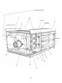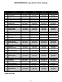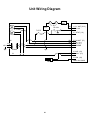
1
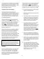
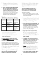
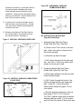
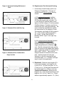
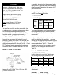
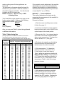
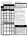
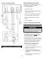
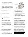
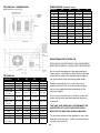
UNPACKING AND INSPECTION
WARNINGS
Should over heating occur, or the gas
supply fail to shutoff, shutoff the manual
gas valve to the appliance before shutting
off the electrical supply.
When replacing an existing heater, it may
be necessary to re-size the venting
system. Improperly sized venting system
can result in vent gas leakage or condensation formation. Refer to the National
Fuel Gas Code ANSI Z223.1 or
CAN/CGA B 149.1 or .2 latest edition.
Failure to follow these instructions may
result in serious injury or death.
This unit heater comes equipped with a
power exhaust system. Failure to follow
these instructions may result in possible
serious injury or even death.
1. Examine unit as received for any
damages. If any damage is found,
proper notation should be made on
the carrierft.s freight bill. Claims should be
made at once.
2. If any parts are missing, claims of
shortage should made to the manufacturer within five (5) days.
3. Check rating plate for correct type of gas
and input.
4. Verify that the electrical rating shown on
the rating plate will meet available power
supply at the point of installation.
GENERAL
PRECAUTIONS
When consulting codes or standards
referenced in this manual, consult the most
recent edition of the code or standard.
1. Read and keep these instructions for safe,
efficient and trouble-free operation.
2. Do disconnect electrical power supply
before making any wiring connections.
Unit must be wired per the wiring
diagram furnished with this heater.
Installation shall conform with local codes
or, in the absence of local codes, with the
National Fuel Gas Code, ANSI Z223.1 or
the CAN/CGA B149 Installation Codes
(latest editions).
3. Do turn off all gas before installing unit
heater(s).
This appliance is a gas-fired power vented
unit heater with propeller-type fan, designed
for suspended mounting in commercial,
industrial and residential buildings. The unit
heater is completely assembled and wired.
Only the usual mounting brackets, gas,
electric and flue connections are needed to
put heater into operation. The unit heater is
certified by the Canadian Standard
Association in accordance with the
American National Standard/Canadian Gas
Association Standard for Gas Unit Heaters
and Gas-Fired Duct Furnaces, ANSI
Z83.8/CGA 2.6 and Z83.8a/CGA 2.6a for
use with natural or LP gases and IAS U.S.
Requirement No. 10-96 for Unit Heaters For
Residential Use.
4. Do make sure that gas pressure never
exceeds 14" w.c. (3.5 kPa).
5. Do check gas inlet supply pressure
immediately upstream of combination
control. The inlet supply pressure should
measure 6-7" w.c. (1.5-1.7 kPa) for
natural gas or 12-14" w.c. (3-3.5 kPa) on
LP gas.
6. Do vent unit(s) to the outside.
2
7. Do maintain a rear clearance of 18"
(45.7cm) or 6" (15.2cm) beyond motor at
rear of uni, whichever is greater, and
access side provide ample air for
combustion and fan operation.
18. Do not attach duck work, air filters or
plastic vent pipe to this unit heater.
19. Do not install below 7 ft. (2.1m) measured
from bottom of heater to the floor in
commercial applications and 5 ft. (1.5m)
for residential applications.
8. Do maintain minimum clearances from
combustible material based on a 160˚F
(70˚C) surface temperature.
9. Do consult piping, electrical and venting
sections in this manual before finalizing
installation.
20. Do not use this appliance if it has
been under water. Immediately call a
qualified service technician to inspect
the appliance and replace any damage
equipment that has been under water.
10. Do keep all literature with this unit
heater.
LOCATION
11. Do not install in potentially explosive or
flammable atmosphere laden with rain
dust, sawdust, or other air-borne
materials.
In locating units, consideration should be
given to the space heating requirements,
availability of gas and proximity to vent
location. The direction of the air stream
should be pointed toward the area of
greatest heat loss. Multiple units should be
located so that the air streams set up a
circulatory movement within the area being
heated. Adjustable louvers are factory
installed on front of the heater.
12. Do not install heaters where there is
high humidity or salt water atmospheres.
This will cause corrosion resulting in
reduction of the normal life of heater.
13. Do not locate in areas where there is a
high concentration of chlorinated, halogenerated or acid vapors in the atmosphere, this will reduce heat exchangers
life.
Do not install unit heater(s) in a confined
space with out providing wall openings to and
from this space. Mounting height at which
heaters are to be installed is critical. The
critical height is from floor to the bottom of
the unit(s) where heater will not deliver the
required amount of heated air to the floor.
14. Do not install in tightly sealed rooms or
small compartments (confined spaces)
without provisions for adequate combustion air and venting.
Unit heaters installed in Aircraft Hangers, Parking
Structures and Repair Garages as applicable, must
be installed in accordance with the Standard on
Aircraft Hangers, ANS/NFPA 409, the Standard for
Parking Structures, ANSI/NFPA 88A and the
Standard for Repair Garages, ANSI/NFPA 88B, and
with the CAN1-B149 codes - latest editions.
15. Do not install heater outdoors.
16. Do not install heater closer to any
combustible materials than what the
heater was tested and listed.
17. Do not block air intake and discharge of
the unit heater.
WARNING: Gas-fired appliances are not designed
for use in hazardous atmospheres containing
chlorinated or halogenated hydrocarbons.
3
4
SUSPENSION
washers and lock nuts, lock washers and nuts,
or a double nut arrangement similarity used on
the unit heater mounting brackets.
Unit(s) must be supported from the structural
part of the building. Do not support from
ceiling boards, roof panels or plaster ceiling.
This heater also can be installed on a shelf.
The mounting brackets need to be attached
as previously indicated. However, for shelf
mounting the brackets will have to be secured
to the bottom of the unit using 1/4" (.6cm)
screws/lag bolts with 1/2". (1.3cm) washers as
overhead joist or truss mounting. Be sure
all clearances to combustible materials are met.
Each unit is provided with two (2) angle
brackets for mounting purposes. See Figure 1A
on page 5 for typical suspension of the heater.
The heater must be installed in a level horizontal
position so that the heater will operate properly.
See Figures 1A and 1B on page 5.
Mounting brackets must be installed first before
lifting heater. Decide if the unit is to be installed
as received; that is with the controls on the left
side when looking at the front of the appliance.
These unit heaters may also be turned 180 ˚
around from the way they were produced at
the factory. Follow these steps for right side
in.turned overin. installation (See Figure 1C on
page 5).
Remove and retain the (3) screws along the top
edge of both the front and back of unit. Make
sure the screws line up on the mounting
brackets with the holes along the front and back
top edges. Secure (1) mounting bracket to
front of the appliance with the retained screw.
Secure the other mounting bracket to the back
side in the same way that the front one was done.
1. Sides become opposite but the front and
back remain in the same relative
position.
Bottom panel now becomes the top and
vice-versa.
2. Remove access panel and rotate 180 ˚
reattach it to the unit. This makes sure that
all labels may be read.
To suspend the heater, fasten the mounting
brackets to the ceiling joist or truss, using 1/4"
(.6cm) screws/lag bolts with 1/2" (1.3cm)
washers. The mounting brackets are slotted to
accommodate joists on 16 - 24 in. (4.9-7.3m)
centers.
3. Remove the louvers and springs. Turn
them over so that the air is deflected
opposite to what it was originally. Replace
louvers springs. Adjust so that they are
open and positioned to direct heated air
to the floor.
This heater may also be hung using same
mounting brackets along with threaded rods.
Attach threaded rod to the heater mounting
brackets, fastening with a top and bottom nut.
COMBUSTION AIR
Adequate provisions of combustion air must
be provided for this unit heater.
Next, drill holes into a steel channel or angle iron
at the same centerline dimensions chosen for
the heater being installed. The steel channels or
angle iron pieces must span and then be
fastened to the appropriate structural members.
Cut the rods to the desired length, push through
holes that were made before and secure with
Since todayft.s buildings and homes are more
tightly built so that less air infiltrates from
the outside, it is very important that all heating
equipment has adequate combustion air.
5
The requirements for combustion and ventilation
air depends on how unit will be installed. That is
either in confined or unconfined spaces. In both
cases enough incoming air is required to
eliminate negative pressure.
This unit heater series is equipped with power
exhaust system. Do not use any additional
power exhaust systems or vent dampers. If
any are used or failure to follow the instructions
provided may result in serious injury or death.
Confined or Unconfined Space
A.) Use the following steps to ensure venting
system is adequately sized:
The National Fuel Gas Code defines an
"unconfined space" as a space whose volume is
greater than 50 cubic feet per 1000 Btu/Hr input
of the installed appliance(s). A confined space
is 50 cubic feet or less per 1000 Btu/Hr input of
the installed appliance(s).
1. Make sure that all unused openings have
been sealed.
2. The venting system must be inspected for
proper size and required horizontal pitch.
Verify there is no blockage or restrictions,
leakage, corrosion or other deficiencies
that may lead to unsafe conditions.
These unit heaters are not recommended for
installation in residential confined spaces. This
is due to the fact at some point in time these air
openings may become blocked or eliminated
by the owner. The National Fuel Gas Code
ANSI Z223.1 or CAN/CGA B149.1 or .2, the most
current, must be strictly adhered to for providing
adequate combustion air.
3. Close all building doors, windows, doors
leading between the space in which
appliance(s) are located and other spaces
of the building. Also turn on all exhaust
fans so that they all operate at there
maximum speeds. However, do not run
summer exhaust fans and make sure all
fireplace dampers are closed.
These unit heaters may be installed in confined
spaces for commercial/industrial installation as
long as these are two permanent openings
located one at the top and one at the bottom.
Each opening shall have a free area not less than
one square inch (6.4cm²) per 1,000 Btu/Hr of
total input rating of all units in the confined space
and communicating with interior areas having
adequate infiltration from the outside.
4. Start up unit heater(s) per the lighting instructions provided and adjust thermostat
so that appliance will operate continuously.
5. With the unit in operation, check all draft
hood equipped appliances after 5 minutes
for any spillage by using either a burning
match or candle.
WARNING
Combustion air openings must, at all times, be
kept free of obstructions. Any obstructions will
cause improper burner operation and may result
in a fire hazard or carbon monoxide injury.
6. Once each appliance, which has been
connected to the venting system, properly
vents when tested from the method outlined
above, all doors, windows, exhaust fans,
fireplace dampers and other gas-burning
appliances may be returned to their
earlier conditions of use.
VENTING
Venting installations shall be in accordance with
Part 7, Venting of Equipment, of the National
Fuel Gas Code, ANSI Z223.1 and applicable
provisions of CAN/CGA B149 Installation Codes
(latest editions), and any applicable provisions
of local building codes.
6
7. If improper venting is observed during any
Unit heaters come with the vent adaptor already
attached so that piping may be installed. Drill
three holes so that pipe can be attached with
3 non-corrosive screws.
of the above tests, the venting system must
be corrected.
8. Should the venting system need to be revised, it must conform with the National Fuel
Gas Code ANSI Z223.1 or CAN/CGA B149
Installation Codes-latest edition. Should the
venting system need revising, it must
approach minimum sizing as determined by
the appropriate table Appendix "G" of the
National Fuel Gas Code ANSI Z223.1.
Vent pipe used shall be no smaller than 3
inches(7.6cm). Check National Fuel Gas
Code for the minimum thickness allowed.
A.) Vertical Venting
1. Before venting vertically, a minimum of 12"
(30.5cm) length of horizontal pipe is required
from the exhaust outlet.
Table 1
ANSI UNIT HEATER VENTING CRITERIA
Category
I
II
III
IV
Description
Venting Criteria
Negative vent pressure
Follow standard
Non-condensing
venting criteria
Negative vent pressure
Condensate must
Condensing
be drained
Positive vent pressure
Vent must be gas
Non-condensing
tight
Positive vent pressure
Vent must be liquid
Condensing
and gas tight.
2. Install a tee fitting at the end of the horizontal
run with a drip leg and cleanout cap as shown
in Figure 2. Slope downward 1/4in. per
foot (.6cm) towards the drip leg.
3. Avoid venting through unheated spaces. This
could cause condensation problems. If vent
pipe does pass through unheated space,
insulate with insulation that is noncombustible and rate at 350 ˚F(175˚C), the first 5 ft.
(1.5m) or 6 ft. (1.8m) of length.
Condensate must
be drained.
4. Single wall vent pipe shall be at least 6"
(15.2cm) from any combustible materials.
Top clearances (top of heater) may be
greater than specified if heat damage such as
surrounding discoloration or material distortion is noticed.
Note: A vent is the vertical passageway to convey flue gases
from to the outside atmosphere. Avent connector pipe
connects the units outlet to a vent or chimney.
Vent connectors serving a category I appliances shall not be
connected into any portion of mechanical draft systems
operating under positive pressure.
All vertically vented unit heaters are category
I venting and all horizontally vented unit heaters
are category III venting.
5. If single wall vent does pass through combustible wall or floor a listed thimble shall be
used. Should type B-0 double wall vent
pass through combustible wall or floor
maintain the vent pipe clearances as specified by the vent pipe manufacturer.
Use Table 1, determining the category requirements. Category III heaters, which are horizontally
vented, shall conform to the venting requirements
in Table 1 shown above along with detailed section
on installing the vent pipe.
6. Do Not use any additional power exhaust
systems or dampers on this unit heater.
Failure To Follow These Instructions could
result in serious injury or death.
Unit heaters for vertical venting may be vented
with either single wall or double wall vent pipe,
and comply with the combustible clearances
provided by the double wall manufacturers.
7. These vertically vented unit heaters shall be
connected to a factory built chimney or
7
Figure 3B HORIZONTAL THROUGH
COMBUSTIBLE WALL
vented into a masonry (or concrete) chimney
lined with material acceptable with recognized standards and the authority having
jurisdiction. Venting into an unlimited masonry
chimney is not allowed. See the National Fuel
Gas Code for common venting.
8. A minimum of 3 corrosion-resistant screws
shall be used to secure vent joints. A listed
vent cap must be utilized to stop drafts and
moisture in the vent.
9. Reference the National Fuel Gas Code for
the vertical distance on a pitched roof that
the cap shall extend. See figure 2.
B.) Instructions for Double Wall
(Type B-0) Vent Pipe:
Figure 2 VERTICAL VENTING SLOPED ROOF
1. Attaching Single Wall Vent Cap to
Double Wall Vent Pipe (Type B-0)
a.) Check for the "Flow" arrow on the vent
pipe. Attach vent pipe to exhaust end of
the double wall pipe.
b.) Slide the cap inside the pipe.
c.) Drill 3 holes through both the pipe and
cap. Use 3/4in. (1.9cm) long sheet metal
screws to secure cap to pipe.
2. Connecting Single Wall Vent Pipe to
Double Wall (Type B-0) Vent Pipe:
a.) Slide single wall pipe into the inner wall
of the double wall pipe.
Figure 3A VERTICAL THROUGH COMBUSTIBLE
FLOOR, ROOF
b.) Drill 3 holes through both walls of the
double wall pipe and through single wall
pipe. Using 3/4" (1.9cm) long sheet
metal screws attache the pipes. Do not
over tighten.
c.) Seal the annular opening by running a
large bead of 350˚F (175˚C) silicone.
The "GAP" between single wall and double
wall pipe shall be sealed. It is not necesssary to fill the full volume of the annular area
8
C.) Requirements For Horizontal Venting
Figure 4 Horizontal Venting With Upward
Pitch
1. Horizontally Vented heaters perform as
Category III Appliances. This type of
venting system follows special venting
criteria:
a.) All residential horizontal installed
heaters shall be vented with either 4 in.
(10.2cm) B-0 double wall vent pipe, 3 in.
(7.2cm) AL29-4C stainless steel or and
agency certified category III venting system.
Certified category III systems can be purchased from your vent pipe distributor . Be
sure to follow the manufactures installation instructions for the category III vent.
The minimum vent length for this system is
3 ft. (1.0m) and the maximum length is
8 ft. (2.4m). A Gary Steel #1092 or
Breident A1092, Type L vent caps may
be used.
Figure 5 Downward Pitch with Drip Leg
b.) All commercial and industrial horizontally vented heaters may use either
certified category III venting system or
single wall galvanized or stainless steel
vent. Should unrecognized single wall be
used, all joints must be sealed with metallic
tape or a silicone suitable for temperatures
above 400˚F (202˚C). Tape must be
wrapped at least 2 times around the vent
pipe. Insulate single wall vent pipe
exposed to cold air or running through
unvented areas. 3 in. (7.62cm) vent caps
may be used in this application.
Figure 6 Downward Pitch Condensation
Drips Out End
2.) Residential: Minimum vent length is 3 ft.
(1.0m) and maximum vent length is 8 ft.
(2.4m) of 4 in. (10.2cm) vent pipe. A 3 in.
(7.6cm) to 4 in. (10.2cm) bell increaser will
be required and 4 in. (10.2cm) vent cap.
Commercial/Industrial: Minimum vent
length is 5 ft. (1.5m) and the maximum vent
length is 30 ft. (9.1m). Each 3 in. (7.6cm)
elbow is approximately equal to 1 ft. (.34m).
9
3.) Venting system shall terminate a minimum of
3 ft. (.9m) above any forced system located
within 10 ft. (3.1m) and a minimum of 4 ft. (1.2m)
horizontally from, or 1 ft. (.34m) above any
door, window, electric or gas meters,
regulators or gravity air inlet into any building.
The bottom of the vent terminal shall be
located a minimum of 1ft. (.34m) above grade
or above the snow line or whichever is the
greater. The venting system shall terminate
not less than 7ft. (2.1m) above grade adjacent
to public walkways.
4.) Horizontal vents shall terminate with a listed
"L" type vent cap. This cap shall maintain a
12 in. (.3cm) clearance from side of wall.
See Figures 4, 5 and 6 on page 5.
9.) Figure 4 shows how to vent piping through
a combustible wall with either a thimble or
type B-0 vent. Check with local authorities
having jurisdiction for the proper procedure.
CLEARANCES
Unit heaters for commercial and industrial
installation shall have a minimum clearance of
7 ft. (2.1m) from bottom of the heater to floor and
residential installation a minimum clearance of
5 ft. (1.5m) from the bottom of the heater to
floor.
Table 2
Clearances to Combustible Material
5.) If condensation should occur, the venting
system shall not terminate over public
walkways or over areas where condensation
or vapor will become a nuisance or hazard
or detrimental to operation of regulators,
relief openings or other equipment.
Based on a 160˚F (70.4˚C)
Top & Bottom:
Vent connector:
Access side:
Non-access side:
Rear:
6.) This vent system must not be used for the
purposes of venting other units.
1 in. (2.54cm)
4 in. (10.2cm)
18 in. (45.7cm)
1 in. (2.54cm)
18 in. (45.7cm)
Make sure that the air intake and discharge
air openings are not obstructed.
7.) On horizontal venting applications, always
maintain a 1/4in. (.6cm) per foot (2.54cm)
rise away from the unit. Include a drain
tee and cleanout near the vent connection.
See Figures 4 and 5. Where local authorities
have jurisdiction, a 1/4 in. (.6cm) per foot
(2.54cm) downward slope away from the
heater is acceptable. Figure 6 allows for
condensation to drain out the end by the
vent cap.
Accessibility clearances must take precedence over fir protection clearances.
Allow a minimum of 18 in.(45.7cm) clearance
at the rear or 6 in. (15.2cm) beyond end of motor
of heater. Make sure access side is provided
with ample air for both combustion and proper
fan operation.
8.) Support the venting (flue) system by screwing three (3) sheet metal screws into each
pipe connection and then supporting at
maximum intervals of 4ft. (1.2m) to prevent
sagging (in Canada, support every 3ft. (1.0m)
minimum intervals).
GAS CONNECTION
WARNING: NEVER USE AN
OPEN FLAME TO CHECK FOR
GAS LEAKS. IF THERE IS A
GAS LEAK, EXPLOSION
OR INJURY CAN OCCUR.
ALWAYS CHECK FOR LEAKS
USING A SOAP SOLUTION.
10
CAUTION
A regulator is required on the propane tanks.
Piping must be gas tight and a non-hardening
pipe compound resistant to the actions of LP
gas must be used.
Check inlet supply pressure at the unit and
upstream of the gas control. Make sure
the inlet supply pressure for natural gas is
6-7in. w.c. (1.2-1.7kPa) and 12-14in. w.c.
(3.0-3.5kPa) for LPG.
Supply piping, including union and external
shutoff valve, are not provided.
Purging air from gas lines and piping
must be done in accordance to the instructions outlined in ANSI Z223.1-latest
edition CAN/CGA-B149 codes.
GAS PRESSURES
Table 3 Pressures
GAS
Never exceed 14in. w.c. (3.5kPa) gas
pressure to the controls on the unit
heater.
NAT.
LPG
MAN.
PRESS.
IN. W.C.
(kPa)
SUPPLY PRESS.
INCHES W.C. (kPa)
MAX.
MIN.
3.5 (.87)
14.0 (3.5)
6.0 (1.2)
10.0 (2.5)
14.0 (3.5) 11.0 (2.7)
The gas line should be as short as possible, be
of adequate size to prevent undue pressure drop
and never be smaller than the connection
provided at the heater. Consult the local utility for
complete details on special requirements in
sizing gas piping. See Table 5 on page 12.
The manifold pressure may be measured by
removing the pipe plug on the downstream
side of the gas control and connecting a water
manometer.
Connect the gas pipe to the heatersft. control,
providing a ground joint union to the controls and
manifold. Provide a drip leg. See figure 7. An
additional manual shutoff valve with a 1/8in. (.3cm)
N.P.T. plugged tapping accessible for test gage
connection shall be installed external to the unit.
Only a small variation in gas input may be
made by adjusting the regulator. In no case
should the final manifold pressure vary by more
than 0.3" w.c. (.1kPa) from the above specified
pressures shown in Table 3. Where the
supplied gas pressure has a greater specific
gravity use the multiplying factors shown in
Table 4.
FIGURE 7
PIPING TO CONTROLS
Table 4 SPECIFIC GRAVITY
CONVERSION FACTORS
Multiply factors to be used with Table 4 when
the specific gravity of gas is other than 0.60.
Natural Gas
Specific
Gravity
0.55
0.60
0.65
Make sure the piping is pitched upward
towards the unit at least 1/4in. (.6cm) per 15ft.
(4.6m) of horizontal run.
LP (Propane) Gas
Factor
1.04
1.00
0.962
Specific
Gravity
1.50
1.53
1.60
Factor
0.633
0.626
0.612
Follow these two (2) methods for input
adjustment:
Method A - Meter Timing
To check a heaters input rate, observe the gas
11
meter, making sure all other appliances are
turned off.
The test hand on the meter should be timed for
at least one (1) revolution. Note the number of
seconds for one (1) revolution. Use this formula
to obtain the BTU/Hr input rate:
BTU/Hr = (Ft³/rev. ÷ No. sec./rev.) x 3600
x Heating Value
If the regulator needs adjustment, the regulator
adjusting screw may be turned clockwise to
increase the pressure or counterclockwise to
decrease the manifold pressure by more than
or less than 0.3" w.c. (8.7kPa).
Method B - Pressure Method
This method determines the input rate by
measuring the gas pressure in the manifold in
inches water column.
Proceed as follows:
Your local utility or gas supplier can give you the
heating value needed. However, the following
representative values may be used:
GAS
BTU/FT³
Natural
1000 - 1150
LPG (Propane)
2500
1.) Find the correct manifold pressure shown
in Table 6 on page 13.
2.) Locate the combination control inside the
heater and then push in on the ON/OFF lever
so that it snaps to the closed position.
Also, you may use Table 5 (meter-timings) based
on different size meters.
Table 5 Meter-timing Gas
3.) Remove the 1/8in. (.3cm) plugged tapping
from outlet of the control and then attached
either a water manometer or "U" shape tube
which is at least 12 in. (.3cm) high.
(Timing required for one revolution is charted for various size
meter dials and various rate of gas input in cu. ft. per hour.
To convert to Btuh, multiply by the heating value of the gas used.)
Time for 1
Revolution
(Seconds)
10
12
14
16
18
20
22
24
26
28
30
35
40
45
50
55
60
70
80
90
100
120
Input, Cu. Ft. per Hour, when meter dial size is:
1/2 F³
1 Ft³
2 F³
5 Ft³
180
150
129
112
100
90
82
75
69
64
60
51
45
40
36
33
30
26
22
20
18
15
360
300
257
225
200
180
164
150
138
129
120
103
90
80
72
65
60
51
45
40
36
30
720
600
514
450
400
36
327
300
277
257
240
206
180
160
144
131
120
103
90
80
72
60
1800
1500
1286
1125
1000
900
818
750
692
643
600
514
450
400
360
327
300
257
225
200
180
150
4.) Put heater into operation per the lighting
instructions and set the thermostat up so
that the heater will continue to operate.
5.) If the manometer or "U" shape tube
pressure indication is less than 1/2" w.c.
(1.3cm) higher or lower than shown in
Table 6, adjust the regulator as described in
Method A Meter Timing. If the manometer
or "U" shape tube pressure indication is
more than 1/2" w.c (1.3cm) higher or lower
than shown in Table 6, check the inlet gas
pressure at heater.
Application
Natural Gas
Propane Gas
Gas Inlet Pressures
6 - 7" w.c. (1.5-1.7 kPa)
12 - 14" w.c. (3-3.5 kPa)
6.) After adjustment has been completed,
make sure the gas flow is shutoff at the
heater by pressing in on the lever so that it
snaps to the OFF position. Replace the
1/8" (.3cm) plug taps and turn gas on.
12
Electrical Connections
7. Restart heater by following the light instructions.
Set thermostat to the desired temperature setting.
Tabel 6 Manifold Pressure & Gas Consumption
BTU/Cu. ft. Spec. Gravity
Manifold Pressure
in. W.C / kPa
Natural
Gas
LP
Propane
1050
0.6
3.5 / 0.87
2500
1.53
10.0 / 2.5
CFH
Natural
Gas
28.6
Model
30
Gal/Hr. LPG
Sec/Cu ft.
Orifice DMS
CFH
45
Gal/Hr. LPG
Sec/Cu ft.
Orifice DMS
CFH
60
12.6
49
57.1
Gal/Hr. LPG
Sec/Cu ft.
Orifice DMS
CFH
75
12.6
49
42.9
63
49
71.4
Gal/Hr. LPG
Sec/Cu ft.
Orifice DMS
50
49
LP
Propane
12.0
0.33
300
56
18.0
0.50
200
56
24.0
0.66
150
56
30.0
0.83
180
56
A fused circuit or circuit breaker must be used
to protect the heater at all times.
Orifice
Qty.
This appliance must be electrically grounded
in accordance with local codes, with the latest
edition of the National Electric Code, ANSI/
NFPA 70, and/or the CSA C22.1 Canadian
Electrical Code, if an external electrical source
is utilized.
2
3
Use wiring with a temperature rating of 105 °C;
run the 115 volt, 60 hertz elelctric power
supply through either a 15 amp fused circuit
or 15 amp circuit breaker to the junction box
of the heater as shown in the wiring diagram.
See Figure 8 on Page 14.
4
If any of the original wire supplied with the heater
must be replaced, replace with wiring material
having a temperature rating of at least 105°C.
5
Tabel 7 Gas Pipe Capacities*
Length
Diameter of Pipe - inches / (cm)
of Pipe
ft. / (m)
15 (4.6)
30 (9.1)
45 (15.7)
60 (18.3)
75 (22.9)
90 (27)
105 (32)
120 (36)
150 (46)
180 (55)
210 ( 64)
240 (73)
270 (82)
300 (91)
450 (137)
600 (183)
1/2 / (1.3)
3/4/ (1.9)
76
73
44
50
218
152
124
105
97
88
80
1 / (2.54) 1-1/4 / (3.2)
440
285
260
190
200
160
168
158
128
120
* In Cu. Ft. per Hour with Pressure Drop of 0.3 in. W.C.
(.1kPa) with Specific Gravity of 0.60)
CAUTION
Power supply must be disconnected before
making any wiring connections to prevent
electrical shock and damage to equipment.
Units must be wired in strict accordancce with
the wiring diagram furnished with the heater.
750
590
435
400
345
320
285
270
242
225
205
190
Install the thermostat according to directions
furnished. The thermostat should be located on
an inside wall about 5 ft. (1.5 m) above floor level.
PLEASE NOTE
The unit has a grounded plug which MUST be
connected to an outlet and breaker which are
grounded. Also, the outlet must have the
proper polarity. If there is a poor ground or
the polarity is reversed, the burners will light
for only a few seconds and go out. To correct,
simply shut power off at the breaker and
verify solid ground and/or reverse the HOT
(Black Wire) and Neutral (White Wire) on the
terminals of the the outlet. Turn power on at
the breaker and cycle unit to verify proper
operation.
178
170
140
119
13
BEFORE OPERATING UNIT HEATER
FIGURE 8 DGH WIRING DIAGRAM
Follow these on-site pre-operational procedures
before putting unit heater into operation:
1. Turn off power supply.
2. Check all clearances.
3. Make sure fan is not contacting casing when
blade is spun by hand.
4. Check to make sure deflector blades are at
a 30° minimum angle from the horizontal.
5. Make sure all electrical connections are
secure.
6. Check for gas leaks.
LIGHTING / OPERATING INSTRUCTIONS
FOR YOUR SAFETY, READ BEFORE OPERATING
WARNING
If you do not follow these instructions exactly
a fire or explosion may result causing property
damage, personal injury or loss of life.
A. This appliance does not have a pilot. It is
equipped with an ignition device which automatically lights the burner. DO NOT TRY TO
LIGHT THE BURNER BY HAND.
B. BEFORE OPERATING, smell around the area
where the appliance is installed for gas. Be sure
to smell next to the floor because some gas is
heavier than air and will settle on the floor.
WHAT TO DO IF YOU SMELL GAS
* Do not try to light any appliance.
PROPER POLARITY IS REQUIRED
* Do not touch any electric switch; do not use
any phone in your building.
* Immediately call you gas supplier from a
neighbors phone. Follow the gas supplier's
instructions.
* If you cannot reach your gas supplier, call
the fire department.
14
C. Use only your hand to move the gas control
switch. Never use tools. If the switch will not
move by hand, don't try to repair it, call a qualified
technician. Force or attempted repair may result
in a fire or explosion.
D. Do not use this appliance if any part has been
under water. Immediately call a qualified service
technician to inspect the appliance and to replace
any part of the control system and any gas control
which has been under water.
OPERATING INSTRUCTIONS
1. STOP! Read the safety information above.
2. Set thermostat to lowest setting.
3. Turn off all electric power to the appliance.
4. This appliance is equipped with an ignition
devise which automatically lights the burner.
Do not try to light the burner by hand.
TO TURN OFF GAS TO APPLIANCE
1. Set thermostat to lowest setting.
2. Turn manual shut-off valve located ouside
of the unit to the closed position.
3. Turn off all electric power to the appliance
if service is to be performed.
4. Remove access panel.
5. Push in on control lever. Lever will spring
to the "OFF" position.
6. Replace the access panel.
OPERATING SEQUENCE
5. Remove the access panel.
6. Push in "ON" control lever. Lever will
spring to the "OFF" postion.
7. Wait five (5) minutes to clear out any gas.
Then smell for gas, including near the floor.
If you smell gas, STOP.! Follow "B" above.
If you don't smell gas, go to the next step.
8. Move gas lever counter clockwise to the "ON"
position.
9. Replace Control access panel.
10. Turn on all electric power to the appliance.
11. Set Thermostat to the desired setting.
12. If the appliance will not operate, follow the
instructions "To Turn Off Gas to Appliance"
and call your service technician or gas supplier.
Upon call from thermostat, power is supplied
to the exhaust and circulating motors. As the
exhaust motor speeds up, the pressure switch
cicuit closes allowing the hot surface ignitor to
become energized. Following the ignition
heat-up period the main gas valve will open to
allow gas flow to the burners. Once the flame
has been detected, the ignitor is de-energized.
When the thermostat is satisfied and the
demand for heat ends, the gas valve is deenergized immediately stoping the flow of gas
to the burners until the next call for heat. The
circulating and exhaust blowers continue to
operate for another 60 seconds before they
shut off. If a flame is not sensed for any
reason, there will be three (3) tries for ignition
and the ignition module will go into lockout
shutting down the entire system at which time
either the thermostat will need to be reset
manually or the power supply must be
shut-off for 5 seconds.
15
TECHNICAL / DIMENSIONS
DIMENSIONS (inches / cm)
30
45
FOR DGH (30, 45, 60, 75)
60
MODELS
A
B
C
D
E
F
G
H
Gas Input
I
J
Fan Dia.
Wt. (lb / kg)
75
26.8 / 68.1 26.8 / 68.1 26.8 / 68.1 26.8 / 68.1
12.2 / 31
12.2 / 31
18 / 45.7
18 / 45.7
16.5 / 41.9 16.5 / 41.9 16.5 / 41.9 16.5 / 41.9
14.9 / 37.8 14.9 / 37.8 14.9 / 37.8 14.9 / 37.8
10.1 / 25.7 10.1 / 25.7 15.9 / 40.4 15.9 / 40.4
7.7 / 19.6
7.7 / 19.6
13.7 / 34.8 13.7 / 34.8
17.5 / 44.5 17.5 / 44.5 17.5 / 44.5 17.5 / 44.5
7 / 17.8
7 / 17.8
7 / 17.8
7 / 17.8
.5 / 1.3
.5 / 1.3
.5 / 1.3
.5 / 1.3
28 / 71.1
28 / 71.1
31 / 78.7
31 / 78.7
22 / 55.9
22 / 55.9
25 / 63.5
25 / 63.5
10 / 25.4
10 / 25.4
14 / 35.6
14 / 35.6
55 / 25
60 / 27
80 / 36
85 / 38
MAINTENANCE & SERVICE
SERVICING OR REPAIRING THIS EQUIPMENT
MUST BE DONE BY A QUALIFIED TECHNICIAN.
Do not use this appliance if any part has been
under water. Immediately call a qualified service
technician to inspect the appliance and replace
any gas control which has been under water.
TECHNICAL
MODELS
30
45
60
75
BTU Input
30,000
45,000
60,000
75,000
BTU Output
24,000
36,000
48,000
60,000
Inlet CFM
505
720
990
1160
Outlet CFM
523
749
653
769
Temp. Rise
44 / 6.6
46 / 7.7
45 / 7.2
48 / 8.8
10 / 3
10 / 3
12 / 3.6
12 / 3.6
25 / 7.6
27 / 8.2
36 / 10.9
38 / 11.6
HP
1/15
1/15
1/12
1/12
RPM
1550
1550
1625
1625
Type
S.P.
S.P.
P.S.C.
P.S.C.
Amp
Total Amps
1.5
2.4
1.2
1.2
2.8
3.7
2.5
2.5
3 / 7.6
3 / 7.6
3 / 7.6
3 / 7.6
Should overheating occur, or the gas valve
supply fail to shut-off, shut-off the manual gas
valve to the appliance before shutting off the
electrical supply.
(F° / C°)
Max. Mounting
Height (ft. / m)
Heat Throw
Prior to any maintenance or cleaning to the unit,
make sure that the gas and electrical supply is
turned off.
(ft / m)
Vent Dia
(in. / cm)
THE UNIT AND VENTING SYSTEM MUST BE
INSPECTED AT LEAST ONCE PER YEAR
BEFORE THE HEATING SEASON BEGINS.
To clean the outside of the appliance, use a soft
cloth and soap solution. Never use an abrasive
to clean any surfaces.
16
MAINTENANCE
1. Remove the access panel.
2. Close manual gas valve and disconnect the union
on the gas line.
3. Disconnect wires from the gas valve along the
with the ignition wires from S1 and S2 on the
module.
4. Remove the screws that attach the burner tray
assembly from the vestibule panel. The entire
assembly comes out as one piece..
5. Carefully clean the burners with a small wire
brush and vacuum.
13. Turn gas and electricity back on and set the
thermostat high enough to cycle the unit to go
through a complete cycle to ensure proper
operation and that there is no gas leakage.
14. Replace access panel and set the thermostat
at the desired setting.
15. Replace any worn or broken components and
wiring as necessary to ensure trouble-free
operation.
16. The heater and its gas valve must be
disconnected from the gas supply piping, and
the supply line must be plugged prior to
conducting any pressure/leak testing of that
system at test pressures in excess of 1/2 psi
(3.5 kPa).
6. While assembly is out, check the orifices to make
there is no blockage.
7. Check each tube type heat exchanger for dirt or
cracking. If dirty, clean with a wire brush and
vacuum. If any cracks are seen, replace the
heat exchanger assembly.
Close the manual shut-off valve to the unit
during any pressure testing of the gas supply
piping system at test pressures equal to or
less than 1/2 psi (3.5 kPa).
SAFETY DEVICES
8. Re-assemble burner tray assembly and gas
piping. Make sure piping is tight.
1) Limit Control
This control is located in the access compartment and the element is located in the air stream
by the tube heat exchanger. This control will
shut off the gas to the burners should overheating result. The limit control will function if
the wall thermostat or some other component(s)
malfunction. Once this limit cools, it will reset
automatically and allow the heater to re-try for
ignition. If the same problem should occur,
immediately shut the gas supply and electricity
off. Call a qualified technician immediately
for service.
9. Check all wiring for loose connections or cracks
in the insulation. Also check to make sure the
rubber tube connected to the pressure switch
has not dried-out and cracked. Replace as
necessary.
10. Re-connect wiring to the gas valve and to the
terminals S1 and S2 on the module.
11. Check circulating blower assembly to make sure
that there is no damage to the fan blade and that
the blade is secured to the motor shaft.
2) Rollout Switches
The switches are located on the bottom burner
panel. If for some reason flames rollout during
an ignition cycle and touch these switches, the
gas flow will be shut off. When cooled, the
switches must be manually reset by pushing in
on the push button located on the top of each
switch.
12. Power exhaust assembly - the motor used is
permanently lubricated. If this assembly needs
cleaning, blow out the cooling air passages of
the motor with compressed air.
17
ADDENDUM - Page 18
SAFETY DEVICES (Continued)
3) Pressure Switch
This is a normally open type switch which monitors
the venting system. When the inducer motor
speeds up to produce enough vacuum in the venting
system, the contacts in the pressure switch close
to complete the circuit to the ignition system. If for
some reason the inducer motor fails to operate or
should the venting system becomes blocked, the
pressure switch contacts open and the unit will not
operate.
LED DIAGNOSTIC CAPABILITY
The red LED on the ignition module indicates the
condition of the control system. The following
codes indicate what type of failure is occurring
and are also shown on the module.
ERROR MODE
Normal Operation
No Power/Internal Fault
Flame Sensed out of Sequence
Ignition Trail Lockout
Pressure Switch
LED INDICATION
Steady ON
Steady OFF
1 Flash
2 Flash
3 Flash
If the pressure switch contacts do not close,
check the following:
TROUBLESHOOTING INFORMATION
1. Verify that venting system does not elbow
within 12" of the 3" dia. vent connect at rear of
the appliance.
2. Check venting system for blockage. Remove
the obstruction(s).
3. Check to make sure the tube between the
power exhaust and the pressure switch is secured
and has not deteriorated. If bad, replace.
4. See if there is air flow at the vent terminal. Replace pressure switch if there is air flow. Replace
the power exhauster if there is no air flow.
4) Hot Surface Ignitor
the ignitor is made from a ceramic material which
must glow red hot until it reaches a required
temperature to ignite the gas flowing through the
burners. If the igniter does not glow red hot, check
the resistance. If less than 100 Ω (ohms), replace
the igniter.
To replace, disconnect the leads S1 and S2 from
the module and remove the two (2) screws holding
the igniter to the burner box cover. Be very careful when installing a new igniter as they can
break easily. Re-connect leads to S1 and S2 on
the module
There are a few basic troubleshooting items that
you may perform if, for some reason, the heater
does not operate. All other troubleshooting MUST
BE DONE BY A QUALIFIED TECHNICIAN.
A. If the heater does not light:
1. Make sure the thermostat is set above the
room temperature.
2. Make sure there is power to the heater.
3. Make sure the main gas supply is on at the
manual shut-off valve.
4. If none of the above solve the problem, contact a qualified technician.
B. Air feels cold coming out of the heater.
1. Make sure burner is lit.
2. If the room was cold to begin with, it will take
a while for the air coming out of the heater to
feel warm.
3. If the air coming out of the heater continues
to feel cold after 5 minutes and the room is not
warming up, contact a qualified technician.
SERVICING AND REPAIR
If a qualified service person cannot solve the
problem, consult your local gas company or the
manufacturer.
When servicing, repairing or replacing parts on the unit,
always give the complete Model and Serial numbers
from the unit rating plate located inside the unit on the
panel in front of the burners.
18
19
WINCHESTER Garage Heater Parts Listing
Ref #
1
2
3
4
5
6
7
8
9
10
11
12
13
14
15
16
17
18
19
20
21
22
23
24
25
26
27
28
29
30
31
32
33
34
35
36
Description
DGH 30
Casing Wrapper
GH-1001
Cover Panel*
GH-1002
Front Panel
GH-1003
Side Panel*
GH-1004
Louvers
GH-1005 (3)
Springs, for Louvers
GH-1005
Collector box*
GH-1008-1
Collector box Gasket*
GH-1007
Ventor Assembly
GH-1040
Ventor Gasket*
GH-1009
Exhaust Outlet*
GH-1020
Heat Exchanger Assbly.
GH-1018-1
Manifold
GH-1010-1
Burner
GH-1044 (2)
Orifice (Natural)
GH-1011 (2)
Orifice (LP)
GH-1011-1 (2)
Burner Box Top
GH-1013-1
Burner Bracket
GH-1014-1
Burner Box Bottom
GH-1015-1
Control Panel
GH-1016
Gas Valve
GH-1032
Pressure Switch
GH-1034
Ignition Module
GH-1035
Hot Surface Ignitor
GH-1039
Transformer
GH-1033
Limit Control
GH-1037
Rollout Switch**
GH-1038
Pressure Switch Hose*
GH-1041
Fan Blade*
GH-1042-1
Fan Guard*
GH-1043-1
Fan Motor*
GH-1036-(1/15)
Mounting Bracket
GH-1023
Thermostat Terminal
H-10021
Power Cord*
H-3257
Terminal Block*
GH-1059
LP Conversion Kit (option
LPG-75GH
DGH 45
DGH 60
DGH 75
GH-1001
GH-1002
GH-1003
GH-1004
GH-1005 (3)
GH-1005
GH-1008-2
GH-1007
GH-1040
GH-1009
GH-1020
GH-1018-2
GH-1010-2
GH-1044 (3)
GH-1011 (3)
GH-1011-1 (3)
GH-1013-2
GH-1014-2
GH-1015-2
GH-1016
GH-1032
GH-1034
GH-1035
GH-1039
GH-1033
GH-1037
GH-1038
GH-1041
GH-1042-1
GH-1043-1
GH-1036-(1/15)
GH-1023
H-10021
H-3257
GH-1059
LPG-75GH
GH-1025
GH-1026
GH-1027
GH-1028
GH-1005 (5)
GH-1005
GH-1030-1
GH-1029
GH-1040
GH-1009
GH-1020
GH-1018-3
GH-1010-3
GH-1044 (4)
GH-1011 (4)
GH-1011-1 (4)
GH-1013-3
GH-1014-3
GH-1015-3
GH-1016
GH-1032
GH-1034
GH-1035
GH-1039
GH-1033
GH-1037
GH-1038
GH-1041
GH-1042-2
GH-1043-2
GH-1036-(1/12)
GH-1023
H-10021
H-3257
GH-1059
LPG-75GH
GH-1025
GH-1026
GH-1027
GH-1028
GH-1005 (5)
GH-1005
GH-1030-2
GH-1029
GH-1040
GH-1009
GH-1020
GH-1018-4
GH-1010-4
GH-1044 (5)
GH-1011 (5)
GH-1011-1 (5)
GH-1013-4
GH-1014-4
GH-1015-4
GH-1016
GH-1032
GH-1034
GH-1035
GH-1039
GH-1033
GH-1037
GH-1038
GH-1041
GH-1042-2
GH-1043-2
GH-1036-(1/12)
GH-1023
H-10021
H-3257
GH-1059
LPG-75GH
* NOT SHOWN
** MODELS USE TWO
20
Unit Wiring Diagram
≠
≠
HIGH
LIM.
2 - R.S.
G.V.
2 - FANS
PR. SW.
BL
Y
1 G.V. HOT (24 V)
2 PR. SW.
T-STAT
3 T-STAT ( W )
Y
R
Y
BK
L1
Y
BK
BK
Y
BL
BL
120 V
L2
5
6
7
8
FAN HOT (F1)
120 V (L1)
24 V ( R )
GROUND
TRANS.
W
W
10 ING. (S1)
11 120 V (L2)
12 IGN. (S2)
IGN.
21
MOD. DH21260S
1-Year Part Warranty / 10-Year Heat Exchanger Warranty
ADAMS LIMITED WARRANTY
Adams, manufacturer of WINCHESTER brand garage heaters, referred to as Adams herein, warrants to the original owner-user
that this Unit Heater will be free from defects in material or workmanship. This warranty is limited to twelve (12) months from the
date of original installation, whether or not the actual use begins on that date, or eighteen (18) months from the date of shipment
by Adams, whichever shall expire first.
The heat exchanger shall have an extended nine (9) year non-prorated warranty in addition to the standard warranty.
Adams’ obligation under this warranty is limited to repair or replacement at Adams’ manufacturing facility in Cleveland, OH, of any
part or parts of this product identified by model and serial numbers which shall be returned with transportation charges prepaid
and which Adams’ examination shall disclose to its satisfaction to be defective. Adams’ parts or products shall not be returned to
the factory without an attached Return Goods Authorization. Repaired products or replacement parts shall be shipped by Adams
F.O.B. Cleveland, OH.
EXCLUSIONS
1. This warranty does not cover labor or other costs incurred in repairing, removing, installing, servicing, or handling of parts
or complete products.
2. This warranty will not apply if the input to the product exceeds the rated input as indicated on the data plate by more than
5%, or if the product in the judgment of the Adams has been subjected to misuse, negligence, accident, corrosive
atmospheres, excessive thermal shock, physical damage, impact, abrasion, unauthorized alterations, or operation contrary
to Adams’ printed instructions, or if the serial number has been altered, defaced, or removed.
3. Adams shall not be liable for any default or delay in performance of its warranty obligations hereunder caused by any
circumstances beyond its control, including but not limited to government restrictions or restraints, strikes, fires, floods, or
reduced supplies of raw materials, energy, or parts.
4. Adams will not be liable for any loss, damage, cost of repair, or incidental or consequential damages of any kind in
connection with the sale, use, or repair of any Adams products. THIS WARRANTY IS IN LIEU OF ALL OTHER
WARRANTIES, EXPRESSED AND IMPLIED, AND ADAMS DISCLAIMS ALL OTHER EXPRESSED WARRANTIES AND
ALL IMPLIED WARRANTIES, INCLUDING IMPLIED WARRANTIES OF MERCHANTABILITY AND OF FITNESS FOR A
PARTICULAR PURPOSE. No person is authorized to assume for Adams any other warranty, obligation, or liability.
Unit Model Number: ______________________
Serial Number: ______________________
(Homeowner to log model/serial numbers found on the unit rating plate located inside heater on the panel in front of burners for easy reference.)