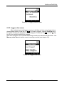
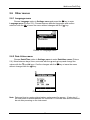
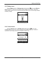
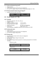
1
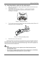
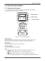
Multinorm MI 6201
FonS MI 6301
Poly MI 6401
User Manual
Version 1.1, Code no. 20 751 260
Multinorm/FonS/Poly
Revision history
Version
Change overview
1.0
Initial version
1.1
USB interface, add new range
Refered to FW version
Multinorm MI 6201 ver.: 1.x
Fons MI 6301 ver.: 1.x
Poly MI 6401 ver.: 1.x
Multinorm MI 6201 ver.: 2.x
Fons MI 6301 ver.: 2.x
Poly MI 6401 ver.: 2.x
Distributor:
ООО «Парма» - эксклюзивный представитель METREL D.D. в России.
Санкт-Петербург, 198216
Ленинский пр-т, 140
тел.: (812) 346-86-10
факс: (812) 376-95-03
[email protected]
www.parma.spb.ru
Producer:
METREL d.d.
Ljubljanska 77
SI-1354 Horjul
E-mail: [email protected]
http://www.metrel.si
© 2004, 2005, 2008 Metrel
2
Multinorm/FonS/Poly
Mark on your equipment certifies that this equipment meets the requirements of the EU
(European Union) concerning safety and interference causing equipment regulations
No part of this publication may be reproduced or utilised in any form or by any means
without permission in writing from METREL.
3
Multinorm/FonS/Poly
Table of contents
1
Introduction ------------------------------------------------------------------------------------------- 6
1.1 General information ------------------------------------------------------------------------------ 6
1.2 Accessories ---------------------------------------------------------------------------------------- 6
1.2.1 Standard accessories ----------------------------------------------------------------------- 6
1.2.2 Optional accessories ------------------------------------------------------------------------ 6
1.3 Warnings -------------------------------------------------------------------------------------------- 6
1.4 Inserting battery cells into the instrument --------------------------------------------------- 7
1.5 Power supply and battery charging----------------------------------------------------------- 8
1.6 New battery cells or cells unused for a longer period------------------------------------ 9
1.7 Periodic calibration ------------------------------------------------------------------------------- 9
1.8 Cleaning--------------------------------------------------------------------------------------------- 9
1.9 Service--------------------------------------------------------------------------------------------- 10
1.10 Standards applied ------------------------------------------------------------------------------ 10
2
Instrument description -------------------------------------------------------------------------2.1 Instrument front panel ------------------------------------------------------------------------2.2 Instrument bottom -----------------------------------------------------------------------------2.3 Instrument input/output ports ----------------------------------------------------------------
3
Measurements-------------------------------------------------------------------------------------- 14
3.1 Normal measuring mode (Measurements) ----------------------------------------------- 14
3.1.1 Overview ------------------------------------------------------------------------------------- 14
3.1.2 Displaying all parameters ---------------------------------------------------------------- 15
3.1.3 Hold function -------------------------------------------------------------------------------- 16
3.1.4 Min, Avg, Max, Cur values--------------------------------------------------------------- 17
3.1.5 Displaying single parameter------------------------------------------------------------- 18
3.1.6 Save function ------------------------------------------------------------------------------- 18
3.2 Logger mode (Measurements) -------------------------------------------------------------- 18
3.2.1 Overview ------------------------------------------------------------------------------------- 18
3.2.2 Description----------------------------------------------------------------------------------- 18
3.2.2.1 Entering logger mode --------------------------------------------------------------- 18
3.2.2.2 Back to normal mode---------------------------------------------------------------- 19
3.3 Normal measuring mode (Sound) ---------------------------------------------------------- 20
3.4 Logger mode (Sound) ------------------------------------------------------------------------- 20
3.4.1 Overview ------------------------------------------------------------------------------------- 20
3.4.2 Description----------------------------------------------------------------------------------- 20
3.4.2.1 Entering logger mode --------------------------------------------------------------- 20
3.4.2.2 Back to normal mode---------------------------------------------------------------- 20
4
Memory management ---------------------------------------------------------------------------4.1 Overview -----------------------------------------------------------------------------------------4.2 Saving measurement records --------------------------------------------------------------4.2.1 Save menu ---------------------------------------------------------------------------------4.2.2 Rename menu -----------------------------------------------------------------------------4.3 Recalling normal/multipoint measurement results -------------------------------------4.3.1 Results recall menu ----------------------------------------------------------------------4.3.2 Results find menu-------------------------------------------------------------------------4.3.3 Results view menu------------------------------------------------------------------------4.3.4 Clearing measurement records---------------------------------------------------------
4
11
11
12
13
21
21
21
23
23
24
24
25
25
25
Multinorm/FonS/Poly
4.4 Recalling logged measuring records ------------------------------------------------------- 26
4.4.1 Loggers recall menu----------------------------------------------------------------------- 26
5
Settings ----------------------------------------------------------------------------------------------5.1 Overview -----------------------------------------------------------------------------------------5.2 Settings menu ----------------------------------------------------------------------------------5.3 Measurements menu -------------------------------------------------------------------------5.3.1 Units menu ---------------------------------------------------------------------------------5.4 Memory clear menu ---------------------------------------------------------------------------5.4.1 Memory clear menu ----------------------------------------------------------------------5.5 Logger menu ------------------------------------------------------------------------------------5.5.1 General --------------------------------------------------------------------------------------5.5.2 Logging interval ---------------------------------------------------------------------------5.5.3 Logger clear menu------------------------------------------------------------------------5.6 Other menus ------------------------------------------------------------------------------------5.6.1 Language menu ---------------------------------------------------------------------------5.6.2 Date & time menu-------------------------------------------------------------------------5.6.3 Battery menu-------------------------------------------------------------------------------5.6.4 Contrast menu ------------------------------------------------------------------------------
27
27
27
27
27
28
28
28
28
28
29
30
30
30
31
31
6
Technical data -------------------------------------------------------------------------------------6.1 Instrument ---------------------------------------------------------------------------------------6.1.1 General --------------------------------------------------------------------------------------6.1.2 Universal measuring port 1 -------------------------------------------------------------6.1.3 Universal measuring port 2 -------------------------------------------------------------6.1.4 Thermocouple measuring port type K -----------------------------------------------6.2 Probe adapter (A 1144) ----------------------------------------------------------------------6.2.1 General --------------------------------------------------------------------------------------6.2.2 Instrument side: ---------------------------------------------------------------------------6.2.3 Probe side: ----------------------------------------------------------------------------------
32
32
32
32
33
33
33
33
33
33
5
Multinorm/FonS/Poly
1 Introduction
1.1 General information
Multinorm MI 6201, FonS MI 6301 and Poly MI 6401 is a portable multi
functional handheld instrument for measuring air parameters, sound and light
measurments and more.
Instrument features
• All measuring probes can be connected simultaneously.
• Specially designed housing for easy connection of measuring probes directly to
the instrument.
• Optional probe connection with prolongation cable (illuminance, luminance,
sound) or telescopic rod (air velocity, relative humidity, air temperature).
• In built memory for storing/logging measured parameters.
• USB interface for communication with a PC.
• In built rechargeable battery.
• 160 x 160 dots graphical LCD with backlight.
• Can be mounted on a tripod.
• Automatic switch-off when not used for 10 minutes.
1.2 Accessories
1.2.1 Standard accessories
See attached sheet for a list of standard accessories.
1.2.2 Optional accessories
See attached sheet for a list of optional accessories that are available on request from
your distributor.
1.3
Warnings
To ensure a high level of operator's safety while carrying out various
measurements and tests using the instrument, as well as ensuring that the test
equipment remains undamaged, it is necessary to consider the following general
warnings:
The test equipment is intended for use in low voltage environment only !
Service is allowed to be carried out only by an authorised person!
Use only standard or optional test accessories supplied by your distributor !
6
Multinorm/FonS/Poly
1.4 Inserting battery cells into the instrument
1.
2.
Make sure that the power supply adapter and all probes are disconnect and
the instrument is off.
Insert battery cells as shown in Picture 1.1. Insert the cells correctly,
otherwise the instrument will not operate and the batteries could be
discharged or damaged.
Picture 1.1 Battery placement
3.
Turn the instrument with the display lower than the battery holder (Picture 1.2)
and put the cover on the battery cells.
Picture 1.2: Closing the battery holder
4.
Screw the cover on the instrument.
If the instrument is not used for a long period of time remove all battery cells from
the battery holder. The enclosed cells can supply the instrument for approx. 8 hours in
worst case (microclimatic probe connected and measuring). This time is extended if air
velocity measurement is switched off.
Warnings!
• When battery cells have to be replaced, turn off the instrument before
opening battery cover.
• Use only power supply adapter delivered from manufacturer or distributor
of the equipment to avoid possible fire or electric shock.
7
Multinorm/FonS/Poly
•
•
•
•
•
Rechargeable NiCd or NiMH battery cells (size AA) are recomended. The
charging time and the operating hours are given for cells with a nominal
capacity of 2100 mAh.
Do not use standard batteries while power supply adapter is connected,
otherwise they may explode!
Do not mix battery cells of different types, brands, ages, or charge levels.
When charging battery for the first time, make sure to charge it for at least
16 hours (24 hours recommended) before switching on the instrument.
During very long charging (>16 h) in hot (40 °C) environment the battery
holder screw might reach maximum allowed temperature for metal part of
handle. In such environment it is advisable not to touch the battery cover
during or immediately after the charging.
1.5 Power supply and battery charging
Power can be supplied to the instrument from:
• USB input. Recommended means for operating the instrument from an
USB input is for data transfer.
• Battery cells. Recommended means for operating the instrument from
Battery cells is for measuring.
• External power supply. Recommended means for operating the instrument
from an external power supply is for battery charging.
Status of the battery cells is indicated by the battery sign at the upper left corner of the
display (see Picture 2.1). Lines in the battery sign indicates the plenitude of the cells.
If the battery sign is broken it idicates that battery cells are not present in the
instrument.
Battery cells are empty.
Battery cells are full.
If the batery sign is animate from empty to full it indicates the charging of the battery
cells. In build charger monitors the charging process and switch off charging when
battery cells are full.
If the instrument is connected to external power supply the battery cells are charged in
all modes of the instrument. If the instrument is connected to USB master device with
capability of supply the power to the host the battery cells are charged but only in
charging mode (before switch on or after switch off the instrument).
Picture 1.3: Charging mode
8
Multinorm/FonS/Poly
1.6 New battery cells or cells unused for a longer period
Unpredictable chemical processes can occur during charging of new battery cells
or cells that were unused for a longer period (more than 3 months). Ni-MH and Ni-Cd
battery cells are affected to capacity degradation (sometimes called as memory effect).
As a result the instrument operation time can be significantly reduced.
Recommended procedure for recovering battery cells:
Procedure
Completely charge the battery.
Notes
At least 16h with in-built charger.
Can be performed with normal work with
the instrument.
Completely discharge the battery.
Repeat the charge / discharge cycle for at
least two times.
Four cycles are recommended.
Complete discharge / charge cycle is performed automatically for each cell using
external intelligent battery charger.
Notes:
•
•
•
•
The charger in the instrument is a pack cell charger. This means that the battery
cells are connected in series during the charging. The battery cells have to be
equivalent (same charge condition, same type and age).
One different battery cell can cause an improper charging and incorrect
discharging during normal usage of the entire battery pack (it results in heating of
the battery pack, significantly decreased operation time, reversing polarity of
defective cell,…).
If no improvement is achieved after several charge / discharge cycles, then each
battery cell should be checked (by comparing battery voltages, testing them in a
cell charger, etc). It is very likely that only some of the battery cells are
deteriorated.
The effects described above should not be mixed with normal decrease of
battery capacity over time. Battery also loses some capacity when it is repeatedly
charged / discharged. The actual decrease of capacity versus number of
charging cycles depends on battery type and is provided in the technical
specification from battery manufacturer.
1.7 Periodic calibration
It is essential that the instrument and its probes are calibrated regularly. We
recommend that calibration of the instrument and its probes is carried out once per year
if there are no different recommendations for specific probe. Please contact your Metrel
distributor for further information on calibration.
1.8 Cleaning
Use soft patch, slightly moistened with soap water or alcohol, to clean the surface
of the instrument and leave it to dry totally, before using it.
9
Multinorm/FonS/Poly
Notes!
• Do not use liquids based on petrol or hydrocarbons!
• Do not spill cleaning liquid over the instrument!
1.9 Service
For repairs under or out of warranty time please contact your Metrel distributor for
further information.
Name and address of manufacturer:
METREL d.d.
Ljubljanska cesta 77
SI-1354 Horjul
Tel.: +386 1 75 58 200, fax.: +386 1 75 49 226, +386 1 75 49 206
http://www.metrel.si
E-mail: [email protected]
1.10 Standards applied
The instrument conforms to the following standards:
EN 61010-1
EN 61326
DIN 5032 P1
DIN 5032 P2
DIN 5032 P3
DIN 5032 P4
DIN 5032 P6
DIN 5032 P7
EN 60751
EN 60584-1
EN 12599
EN ISO 7726
ISO 10526
ISO 10527
Safety
EMC
Photometry; methods of measurement
Photometry; Operation of electric lamps and measurement
of the respective quantities
Photometry; Terms of measurement on gas luminaires
Photometry; Measurement of luminaires
Photometry; Photometers; Concepts, characteristics and
their designation
Photometry; Classification of illuminance meters and
luminance meters
Industrial platinum resistance thermometer sensors
Thermocouples - part 1: reference tables (IEC 605841:1995);
Ventilation for buildings - Test procedures and measuring
methods for handling over installed ventilation and air
conditioning systems
Ergonomic of thermal inviroment - Instruments for measuring
physical quantities
CIE STANDARD colorimetric illuminants
CIE STANDARD colorimetric observers
10
Multinorm/FonS/Poly
2 Instrument description
2.1 Instrument front panel
The instrument has 13 keys and a graphical display with 160x160 dots.
Display is divided into three parts or windows.
Status window
Main window
Function window
Picture 2.1: Instrument front panel
Status window:
Here are some general information about date, battery status, duration of the
measurement, play / stop / pause / record icons and various warnings.
Main window:
Here are measurement results or various menus.
Function window:
Here are descriptions of function keys.
Keys:
•
,
: switch between parameters, between building and room, etc.
•
,
: change certain values – room number, interval, etc.
•
: starts or stops measurement, confirms changes in settings, etc.
•
to
: perform action written on the display above particular function key.
11
Multinorm/FonS/Poly
•
•
•
•
: changes the set of function keys.
: returns to the previous menu.
: toggles backlight.
: turns on/off the instrument.
2.2 Instrument bottom
1
2
3
4
Picture 2.2: Instrument bottom
1. Nut for mounting a tripod adapter
2. Serial number
3. Information label
4. Battery compartment
12
Multinorm/FonS/Poly
2.3 Instrument input/output ports
Picture 2.3: Instrument input/output ports
1. Universal measuring port 1
Illuminance probe type B
Luminance probe type B
Black globe thermometer
Sound probe class 1
Sound probe class 2
A1092
A1132
A1131
A1146
A1151
2. Universal measuring port 2
Probe adapter
A1144
Picture 2.4: Proper adapter connection to universal measuring port 2
Probe adapter supports the following probes:
Microclimatic probe
A1091
Temperature and humidity probe
A1127
3. Thermocouple measuring port type K
Thermocouple probe type K
A1128
4. USB communication interface
5. Power supply adapter input
13
Multinorm/FonS/Poly
3 Measurements
When the instrument is switched on it always starts in the Main menu, which is
shown in Picture 3.1. Here one can choose between five main options.
•
•
•
•
•
•
Measurements (supported by Multinorm MI6201/Poly MI6401): in this option
the instrument is measuring all parameters from the probes which are connected
to the instrument.
Sound (supported by Multinorm MI6201/FonS MI6301): this option (together
with sound probe A1146 or A1151) activates sound level meter.
Results Recall/Clear: in this option saved measurement results can be recalled
or cleared.
Loggers Recall/Clear: in this option recorded loggers can be cleared or their
statistics can be recalled.
Settings: in this option various settings of the instrument can be changed.
Help: in this option a brief help about handling the instrument is displayed.
Picture 3.1: Main menu
Instrument has two different measuring modes under Measurments and Sound option:
normal and logger measuring mode.
3.1 Normal measuring mode (Measurements)
3.1.1 Overview
This measuring mode is intented to collect and handle measuring data from all
probes that could be connected to different instrument measuring ports. For each
parameter the instrument can offer:
Value
current
minimum
maximum
average
start measurement
stop measurement
Abbreviation
cur
min
max
avg
Start
Stop
Tabela 3.1: Value table
14
Multinorm/FonS/Poly
Normal measuring mode has two sets of function keys. First set consists of Hold ,
Value , Single and Save , and the second set of Logger and some custom keys for
different parameters and probes.
For probe description and its connection to the instrument see user manual for
particular probe.
3.1.2 Displaying all parameters
To enter normal measuring mode select Measurements option in the Main
menu and press the
key. Picture 3.2 shows display before the measurement is
started. The probes are already plugged in the corresponding measuring ports.
Measurements are stopped, which is indicated with stop icon and also with dashes
instead of values. All parameters that can be measured with currently connected probes
are in the main window.
Picture 3.2: Normal mode – microclimatic probe connected, measurements stopped
The instrument starts and stops measuring by pressing the
key. The
instrument checks which probes are plugged-in approximately once every second. If a
new probe is plugged-in during the measurement, measurements are stopped and
reset.
Picture 3.3: Normal mode – microclimatic probe connected, measurements running
If there are no probes connected there is NO PROBE caption displayed in the main
window of the display (Picture 3.4).
15
Multinorm/FonS/Poly
Picture 3.4: Normal mode – no probe connected
3.1.3 Hold function
If the F1 ( Hold ) key is pressed when the instrument is measuring, the momentary Min,
Avg, Max or Cur values are retained. Measurements are proceeding normally
meanwhile in the background. Note that the F4 (Save ) key like the
key stops
measurement during hold mode. To return to normal display mode press F1 (Hold)
again. In the
Picture 3.5 graphical representation of the Hold function is shown.
Start
Hold
Stop
Actual result
t
Start
Stop
Actual result
t
Picture 3.5: Hold function
16
Multinorm/FonS/Poly
3.1.4 Min, Avg, Max, Cur values
Instrument samples current values of measured parameters from all connected
probes approximately once every second. While measuring, the instrument calculates
average and remembers the maximum and the minimum value for each parameter
(physical quantity) during the measurement. Min, Avg and Max values for all probes
are reset at the start of the measurement or when a new probe is connected to the
instrument.
One can switch between Min, Avg, Max and Cur values with the F2 ( Value ) key.
This key switches between Min, Avg, Max and Cur values for all probes connected. It
is also possible to switch only value for one probe with
or
key. Note that you can
switch between these values also during measurement, and not only after the
measurement is stopped.
Picture 3.6 shows a graphical presentation of the Cur, Min, Avg and Max values.
Stop
Start
Max
Actual result
t
Stop
Start
Actual result
t
Min
Stop
Start
Actual result
Avg
t
Picture 3.6: Max, Min and Avg values
17
Multinorm/FonS/Poly
3.1.5 Displaying single parameter
First select the desired parameter with the
and
keys. Then press the F3
(Single ) key to enable this function which allows you to focus on only one measurement
parameter. All values of this single parameter are displayed (Min, Avg, Max, Cur, Start
Time, Stop Time). Press the F3 ( All ) key to return to display of all measurement
parameters. Picture 3.7 shows single parameter displays for air temperature and
illumination parameters.
Picture 3.7: Single measurements
3.1.6 Save function
Press the F4 ( Save ) key to enter Save menu (described in chapter 4.2.1) which
allows you to store measurements. If measurement is not already stopped, pressing the
F4 ( Save ) will automatically stop the measurement.
3.2 Logger mode (Measurements)
3.2.1 Overview
This measuring mode is intented to collect, handle and periodicly save
measuring data in non volatile memory from all probes that are connected to different
instrument measuring ports. Time period between two memorized measurements can
be set up between 2 s and 60 min. This data can be downloaded to PC by A1166
LabLink PRO/ A1134 SensorLink PRO (see corresponding user manual). For proper
probe connection see the user manual for desired probe.
3.2.2 Description
3.2.2.1 Entering logger mode
In the normal measuring mode change the function keys to second set by
pressing the
key. Then press the F1 (Logger) key. Instrument is now in logger mode,
caption LOG appears in the status window.
Logging procedure saves measurement records into non volatile memory. To
define (change) location levels of the logging measurement records press the F4 ( Loc )
key.
18
Multinorm/FonS/Poly
In the logger mode the instrument automatically stores all measurements in every
logging interval. This interval is set in Logger settings (described in chapter 5.5.2).
After the measurements are stored, the Min, Max and Avg values are reset and the
instrument starts measuring again for the next logging interval.
Picture 3.8: Logging mode – microclimatic probe connected, logging in progress
Instrument starts logging when the
key is pressed. Icon from normal mode
is replaced with icon in logger mode. The number of concluded intervals is displayed
beside the LOG caption. For every logging interval the instrument stores all results that
can be measured until logging is stopped by pressing the
key.
The F2 ( Value ) key switches between Min, Avg, Max and Cur values, as in
normal measuring mode. Min, Avg and Max values are cleared at the beginning of
each interval, so they are calculated for each interval separately and not for the whole
duration of logging. Elapsed time in the upper left corner of the status window also
represents elapsed time of each interval and not the whole duration of logging.
key is pressed again or the memory is full.
Instrument is logging until the
Instrument can store approximately 4000 values. Table 3.1 shows how long the
instrument is logging if the memory is 100% free (cleared) with different logging
intervals.
Logging interval
2s
10 s
60 s
10 min
60 min
Estimated logging time
2 hours 15 min
11 hours
2 days 20 hours
28 days
170 days
Table 3.1: Interval and estimated logging times
If you intend to keep logging for more than just a few hours, it is recommended to
use power supply adapter to avoid discharge of the batteries.
3.2.2.2 Back to normal mode
Change the function keys to first set by pressing the
key. Then press the F1
(Norm ) key to return to the normal mode. Press the
key to reach Main Menu.
19
Multinorm/FonS/Poly
3.3 Normal measuring mode (Sound)
Instrument has 3 sound measurement submodes. Normal sound level meter
(SLM), octave frequency analysis (1/1) and one third octave frequency analysis (1/3).
Picture 3.9 Three sound measurement submodes
For more information about sound level measurements see sound probe user manual.
3.4 Logger mode (Sound)
3.4.1 Overview
This measuring mode is intented to collect, handle and periodicly save sound
level measuring data in non volatile memory. Time period between two memorized
measurements can be set up between 2 s and 60 min. This data can be downloaded to
PC by A1162 SoundLink PRO / A1167 Soundlink LITE (see corresponding user
manual). For all sound level measuring details see the user manual for sound probe.
3.4.2 Description
3.4.2.1 Entering logger mode
In the normal measuring mode change the function keys to second set by
pressing the
key. Then press the F4 (Logger) key. Instrument is now in logger mode,
caption LOG appears in the status window. Logging procedure saves measurement
records into non volatile memory. To define (change) location levels of the logging
measurement records press the F4 ( Loc ) key. Logging sound measurements is no
different than logging measurements from any other probe.
In the logger mode the instrument automatically stores all measurements in every
logging interval. This interval is set in Logger settings (described in chapter 5.5.2).
After the measurements are stored, all values are reset and the instrument starts
measuring again for the next logging interval.
3.4.2.2 Back to normal mode
Press the F1 ( Norm ) key to return to the normal mode. Press the
Main Menu.
20
key to reach
Multinorm/FonS/Poly
4 Memory management
4.1 Overview
The instrument has enough memory to store approximately 4000 measurement
records. Each such measurement record contains:
• All values (Min, Avg, Max, Cur) of every probe that was connected at the
time of saving the measurement, or at the end of logging interval.
• Some additional information such as the location and time stamp of the
measurement is also stored.
• All values from the sound level measurement (including frequency analysis
data).
Memory is organised in two levels, each level having 100 different locations. First
level represents buildings, and second level represents rooms. Each combination of
both levels represents a memory location under which any number of measurements
can be stored.
The instrument has a single memory buffer for 4000 measurement records,
intended for all measurement modes (normal or logger). When the end of the buffer is
reached the instrument searches from the beginning of the buffer if any measurements
were deleted, and so there is still some free memory space. But the logger requires
coherent free memory space. When it comes to the end of the buffer logging is not
possible anymore and memory data should be downloaded to PC and cleared in order
to enable logging again.
4.2 Saving measurement records
When memory is completely empty (after clearing both memory and logger) every
location is empty and is designated only by number (01-100). After the first
measurement is stored in the desired location, it is renamed from a number to a default
name (Building 01-100 and Location 01-100) or to an optional name that can be written
in special menu (Rename menu described in chapter 4.2.2).
Once the location is renamed (to a default or optional name) it keeps its name until
all measurements on this location are deleted. If all measurements on certain location
are deleted, the location name is also deleted and changed back to a number (01-100).
When the next measurement is saved on this location it is again renamed to a default or
optional name.
21
Multinorm/FonS/Poly
Picture 4.1: Memory structure
22
Multinorm/FonS/Poly
4.2.1 Save menu
When in normal measuring mode press the F4 ( Save ) key, and the instrument
enters Save menu. In Save menu (Picture 4.2) one can select on which memory
location the measurement result will be saved. Move between Level1 and Level2 with
and
keys and select location with the
and
keys (press and hold for fast
the
rewind). Once memory location is set, it can be renamed in Rename menu by pressing
the F3 ( Name ) key. Otherwise the default name will be used. By pressing the F4 ( Save )
key, the measurement record is stored on the selected memory location and the
instrument returns into normal measuring mode. One can exit Save menu without
storing any measurements by pressing the
key at any time.
Picture 4.2: Save menu
Note: If the memory level is empty (no measuring results saved under that level), it is
designated only by number (01-100). After the first measurement is stored under
empty levels, they are renamed from a number to a default name (Level1:
Building 01-100 and Level2: Location 01-100) or to an optional name that can be
written in special menu (Rename menu described in chapter 4.2.2).
4.2.2 Rename menu
Press the F3 ( Name ) key in Save menu to reach Rename menu. Here one can
rename a location. Select a character with the , ,
and
keys and confirm it
with the
key. Use function keys F3 (Space) and F4 (BckSp) to insert space and to
delete characters. Confirm the whole name with the F2 ( O.K. ) key. Rename menu is
shown in Picture 4.3.
Picture 4.3: Rename menu
23
Multinorm/FonS/Poly
In the Save menu one can still decide not to save the measurement record, or to
save it in different memory location. In that case the location name that was renamed in
Rename menu is not changed. Location is renamed only if a measurement record is
stored in it.
4.3 Recalling normal/multipoint measurement results
4.3.1 Results recall menu
Choose Results Recall/Clear option in Main menu and press the
key to
enter the Results recall menu. Here one can set four different filters in order to select
which measurement records are recalled. It is possible to filter measurement records by
memory location levels (building, location), start date and stop date. Picture 4.4 shows
Results recall menu.
Picture 4.4: Memory recall menu
Move between four filters with the
and
keys. By pressing the F3 ( Fon )
key selected filter is enabled.
and
keys (press and hold for fast rewind).
Select memory location with the
Setting start and stop date is a bit different and is shown in
Picture 4.5. First select start or stop filter with the
and
keys. Then move to the
desired field with the
or
key. Once the field is selected change it with the
and
keys. Parameter that is not inverted is being set, in this case the month.
By pressing the F2 ( Foff ) key the selected filter is disabled, meaning all
measurement records regardless of this filter will be found.
Picture 4.5: Setting start date
24
Multinorm/FonS/Poly
4.3.2 Results find menu
By pressing the F4 ( Find ) key in Results recall menu, the instrument searches
for all measurement records according to filters and goes into Results find menu. Here
the results of the search are displayed. For every measurement record the memory
location where it was stored and the date of the measurement (start date) is displayed.
One can browse through results with the
and
keys. By pressing the F4 ( View ) key
the actual results of a stored measurement are displayed.
Picture 4.6: Results find menu
4.3.3 Results view menu
By pressing the F4 ( View ) in Results find menu, the actual results of recalled
measurement record are displayed. The display and the functionality of the keys are the
same as in normal measuring mode, except there are no F1 ( Hold ) and F4 ( Save )
keys.
Picture 4.7: Results view menu
4.3.4 Clearing measurement records
It is also possible to delete measurement records in Results find menu (Picture
4.6). Press the F2 ( Clear ) key to delete one selected measurement, or the F1 (C.All ) key
to delete all recalled measurement records.
To clear all measurement records set all filters to Filter Off with F2 ( Foff ) key in
Results recall menu and then use the F1 ( C.All ) key in Memory find menu. This can
also be done more easily in Results clear menu (described in chapter 5.4).
25
Multinorm/FonS/Poly
4.4 Recalling logged measuring records
4.4.1 Loggers recall menu
Choose Loggers Recall/Clear option in Main menu and press the
key to
reach Loggers recall menu. This menu is completely the same as Results recall
menu described in chapter 4.3.1. Use the same procedures to filter out which loggers to
recall or to delete. The difference is only in View menu, where the statistics of the
recalled logger records and not the actuall record can be displayed. Such statistics is
shown in Picture 4.8.
Picture 4.8: Statistics of the recalled logger
It is possible to see which measured (not calculated) parameters were logged, on
which memory location the logger is stored, start and stop time, logging interval and the
number of measuring record that were logged.
26
Multinorm/FonS/Poly
5 Settings
5.1 Overview
The intention of the Settings menu:
• Change settings for calculation parameters.
• Change logger settings and memory clear option.
• Change instrument settings and view battery supply voltage.
In the following chapters only general settings are explained. Settings regarding
calculation parameters that are generated from probe parameters are explained in
the correspondent probe user manual.
5.2 Settings menu
Choose Settings option in Main menu and press the
key to enter. Choose
designated option and press the
key again to enter its submenu. Arrows on the left
side of the screen indicate that there are more options, which can be reached by
scrolling up and down with the
and
keys. Picture 5.1 shows Settings menu.
Picture 5.1: Settings Menu.
5.3 Measurements menu
Choose Measurements option in Settings menu to reach Measurements menu.
Options in this menu are refered to measured and calculated parameters. These
options are described in the user manuals for coresponding probes (except Units
menu). Select desired option and press the
key to reach its menu.
5.3.1 Units menu
Here one can switch between SI and US units. Select an option with the
and
keys and confirm selection by pressing the
key. Press the
key to exit Units
menu without changes.
27
Multinorm/FonS/Poly
5.4 Memory clear menu
5.4.1 Memory clear menu
Choose Memory clear option in Settings menu and press the
key to enter
Memory clear menu (Picture 5.2). Menu shows how much memory is still free and how
many measurement records have already been stored. Press the F3 ( Yes ) key to clear
the memory. Caption Clearing and a bar graph showing the progress in % are
displayed. Press the F4 ( No ) or the
key to exit menu without clearing the memory.
Note that all measurement records, but no loggers, are deleted with this action. Use
Logger clear menu to delete loggers (see chapter 5.5.3).
Picture 5.2: Memory clear menu
5.5 Logger menu
5.5.1 General
Choose Logger Settings option in Settings menu to enter Logger menu. There
are two options in this menu. Select desired option and press the
key to enter
submenu.
5.5.2 Logging interval
Select logging interval with the
and
keys. Note that the interval can only be
set in predefined intervals between 2 seconds and 60 minutes. Confirm selection by
pressing the
key or exit without changes by pressing the
key.
28
Multinorm/FonS/Poly
Picture 5.3: Logging Interval menu
5.5.3 Logger clear menu
Menu shows how much logger memory is still free and how many loggers have
already been stored. Press the F3 ( Yes ) to clear all loggers. Caption Clearing and a
bar graph showing the progress in % are displayed. Press the F4 ( No ) or the
key
to exit menu without clearing the loggers.
Note that all loggers, but no saved measuring records, are deleted with this action. Use
Memory clear menu to delete saved measuring records (see chapter 5.4).
Picture 5.4: Logger clear menu
29
Multinorm/FonS/Poly
5.6 Other menus
5.6.1 Language menu
Choose Language option in Settings menu and press the
key to enter
Language menu (Picture 5.5). Choose between different languages and confirm
selection with the
or leave the menu without changes with the
key.
Picture 5.5: Language menu
5.6.2 Date & time menu
Choose Date&Time option in Settings menu to enter Date&time menu (Picture
5.6). Move between days, hours, seconds with the
and
keys and change the
values with the
and
keys. Confirm changes with the
key or leave the menu
without changes with the
key.
Picture 5.6: Date & time menu
Note: Date and time is running during battery replacement for approx. 10 minutes. If
the instrument is without bateries for more than 10 minutes date and time should
be set after powering on the instrument.
30
Multinorm/FonS/Poly
5.6.3 Battery menu
Choose Battery option in Settings menu and press the
key to enter Batterty
menu (Picture 5.7). Here one can see the actual voltage of the battery. The power
supply adapter should not be connected during the battery test to avoid wrong readings
of battery voltage!
Picture 5.7: Battery menu.
5.6.4 Contrast menu
Choose Contrast option in Settings menu and press the
Contrast menu (Picture 5.8). Set the contrast with the
and
expressed in percentage and can be changed in steps of 1%.
Picture 5.8: Contrast menu
31
key to enter
keys. Contrast is
Multinorm/FonS/Poly
6 Technical data
6.1 Instrument
6.1.1 General
•
•
•
•
•
•
•
•
•
•
•
•
•
Communication:
RS 232 serial interface for connection to a PC, fully
opto isolated, 57600 baud, 9 pin D-type connector.
Memory:
approximately 4000 values
Logger:
approximately 4000 values
Dimensions (WxHxL):
110 x 85 x 220 mm
Weight:
0.56 kg (without battery)
Battery:
6 x 1.2 V AA rechargeable, with internal charger
Display:
graphical LCD with backlight, 160 x 160 dots
Pollution degree:
2
Protection degree:
IP 40
*Working temperature range:
-10 ºC to 50 ºC
*Storage temperature range:
- 20 ºC to 70 ºC
*Maximum humidity:
95 %RH non-condensing
Conforms to: Safety:
EN/IEC 61010-1
Electromagnetic compatibility (emission and immunity): IEC 61326
*Attention: This data can be changed regarding the temperature ranges of the battery
and the probes.
6.1.2 Universal measuring port 1
•
•
•
Digital interface
XLR 5MP connector with custom pin assignment
Analog voltage measuring input
o for measuring illuminance with A 1092 probe:
Range
0.01 lux to 19.99 lux
20.0 lux to 199.9 lux
200 lux to 1999 lux
2000 lux to 20000 lux
Accuracy
± (0.01 lux + 0.5% of r.)
± (0.1 lux + 0.5% of r.)
± (1 lux + 0.5% of r.)
± (10 lux + 0.5% of r.)
o for measuring luminance with A 1132 probe:
Range
0.1 cd/m2 to 39.9 cd/m2
40 cd/m2 to 399 cd/m2
400 cd/m2 to 3999 cd/m2
4000 cd/m2 to 40000 cd/m2
Accuracy
± (0.1 cd/m2 + 0.5% of r.)
± (0.5 cd/m2 + 0.5% of r.)
± (1 cd/m2 + 0.5% of r.)
± (10 cd/m2 + 0.5% of r.)
32
Multinorm/FonS/Poly
6.1.3 Universal measuring port 2
•
•
•
Digital interface
9 pin D-type connector with custom pin assignment
5 V and 18 V supply voltage for probes through probe adapter (A 1144)
6.1.4 Thermocouple measuring port type K
•
Standard thermocouple K type input
Range
-200 °C to +1400 °C
Accuracy
±(1.0 °C + 0.2% of r.)
6.2 Probe adapter (A 1144)
6.2.1 General
•
•
•
•
•
•
Dimensions (WxHxL): 30 x 35 x 140 mm
Weight: 0.07 kg
Working temperature range:
-10 ºC to 40 ºC
Storage temperature range:
- 20 ºC to 70 ºC
Maximum humidity:
95 %RH non-condensing
Conforms to:
Safety: EN 61010-1
Electromagnetic compatibility (emission and immunity): EN 61326
6.2.2 Instrument side:
•
•
•
Digital interface
9 pin D-type connector with custom pin assignment
5 V and 18 V supply voltage inputs
6.2.3 Probe side:
•
•
•
•
•
5 pin Mini XLR connector with custom pin assignment
Digital interface
5 V and 18 V supply voltages for the probes
Demodulator
Two analog voltage measuring inputs for measuring temperature and relative
humidity:
o Relative humidity:
Range
0 %RH to 100%RH
Accuracy
± 0.1 %RH
o Temperature:
Range
-40 ºC to +60 ºC
Accuracy
± 0.1 ºC
33