1
DBF110 DRYER EXHAUST BOOSTER SYSTEM INSTALLATION INSTRUCTIONS
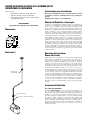
DBF110 Includes:
Installation Guidelines
1 DBF 110 Dryer Booster Fan
1 Fan Mounting Bracket and Hardware
Please note: DBF 110 fans are not explosion proof. Do not use the fans if
a potentially explosive situation may exist.
1 Small Wall Sign Indicating Proper Operating Procedure
DO NOT USE with heated air in excess 140ÞF (60ÞC).
Important Notice
Read and Save these instructions for future reference.
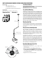
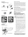
Dimensional Data
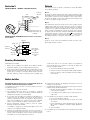
Illustration 1
DBF110
(DBF110)
Fan and Switch Mounting
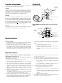
The DBF110 is to be mounted a minimum of 5 linear (not equivalent) feet from
the dryer outlet. A secondary lint trap can be used in applications where
excessive dryer lint generation is likely or to increase the time interval between
routine maintenance of the Dryer Booster Fan (See illustration to left). An NB
mounting bracket attached to a rafter or joist should be used to stabilize the
fan. Although not recommended, a vertical rigid duct may support the fan if
the duct is securely stabilized. (Consult local codes prior to supporting the fan
in the duct alone.) Duct work should be attached to the inlet and outlet of the
fan by means of FC vibration isolation clamps (not included) or duct tape. The
duct connection should be properly sealed to prevent leakage and loss of fan
performance. Flex duct connections between the dryer duct connection and
exhaust duct should be stretched as smooth as possible.
Calculating Duct Run
To calculate the length of your planned duct run, measure from the dryer
to external venting point in roof or wall. For each bend or elbow add 5-7
feet to your total duct run calculations. The DBF110 can be used on runs
up to 108 feet.
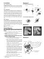
Pressure Sensor Switch Operation
Alternative Location
Secondary Lint Trap
Fantech’s DBF110 is equipped with Fantech's Patented DB10 pressure
switch. The DB10 is a positive pressure sensing switch which
recognizes dryer operation and activates the booster fan from an
independent electrical circuit. This eliminates connections through the
dryer circuit which may void the manufacturers’ warranty as well as
manual systems which require the attention of the operator or costly
current/temperature sensing systems.
The electricity to the booster fan is connected in series through a
normally open terminal on the switch. A pressure tap is connected to a
fitting on the side of the switch. When the dryer begins operation, positive pressure in the duct causes the switch diaphragm to expand, closing
the circuit to the booster fan. An integral delay-on-break timer in the
switch will cycle the fan on for intervals of 10 minutes. This will continue
until the dryer has stopped and the timer delay period has lapsed. Drying
cycles, the booster fan, the delay timer and the pressure switch are not
adversely affected by the starting/stopping intervals.
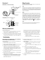
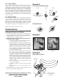
Sensitivity Adjustment Instruction
a. Disconnect power to the booster fan.
b. Looking from the inlet (dryer side), the switch should be at the
12-o-clock position.
c. Remove the 2 mounting screws holding the switch to the fan.
d. Rotate the switch to the 10-o-clock position for less sensitivity or
2-o-clock position for more sensitivity then secure it there, you may
have to adjust (bend) the bracket to fit. Secure the switch with the
2 screws previously removed.
e. Apply power to the fan and check for operation.
12-o-clock
10-o-clock
2-o-clock