1
Fan Installation
Step 1. Selecting Fan Location
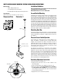
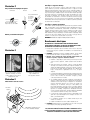
Fan must be mounted a minimum of 15 feet from the dryer outlet.
In order to perform recommended maintenance, fan location should allow
sufficient access for service. Refer to dimensional drawings shown
above.
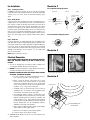
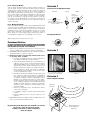
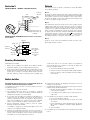
Illustration 2
Correct Mounting of Diaphragm Switch
Horizontal
Vertical
Switch mounted
properly
above and
below
duct.
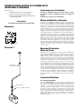
Step 2. Mount Bracket
Using the wood screws provided, attach the mounting bracket to a
support beam at the selected location. Bracket is provided with grommets in order to isolate any vibration and prevent the transmission of
sound through the structure. Be careful not to overtighten. Fan mounting can be in any angle (see ill. 2), however, vertical mounting is recommended to reduce condensation buildup in the fan. If a horizontal installation is necessary and condensation buildup may pose a problem, a ¼"
hole drilled in the bottom of the housing (along with an NPT insert [by
others] and drain tubing) may be installed to allow condensation to
drain.
Angled
Switch mounted
properly above
duct.
Incorrect Mounting of Diaphragm Switch
Step 3. Mount Fan
For proper operation, the switch diaphragm must be positioned vertically. (Illustrations below show diaphragm position for horizontal, vertical and ducts installed at an angle.) Wiring box should be positioned for
easy access. Attach fan to the mounting bracket with the self tapping
screws provided. Care should be taken not to strip the plastic housing.
Although screw pilot holes are not required, 3/32" (or smaller) pilot
holes are recommended.
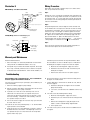
Illustration 3
NOTE: Steps 2 & 3 may be reversed.
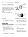
Electrical Connection
DO NOT CONNECT POWER SUPPLY UNTIL FAN IS COMPLETELY INSTALLED.
MAKE SURE ELECTRICAL SERVICE TO THE FAN IS LOCKED IN "OFF"
POSITION.
1. This unit has rotating parts and safety precautions should be exercised during installation, operation and maintenance.
2. CAUTION: "For General Ventilation Use Only. Do Not Use To Exhaust
Hazardous Or Explosive Materials And Vapors."
3. WARNING: TO REDUCE THE RISK OF FIRE, ELECTRIC SHOCK, OR INJURY
TO PERSONS - OBSERVE THE FOLLOWING:
a. Use this unit only in the manner intended by the manufacturer. If you have questions, contact the factory.
b.Before servicing or cleaning, switch power off at service
panel and lock service panel to prevent fan from being
switched on accidentally. When the service disconnecting
means cannot be locked, securely fasten a prominent warning device, such as a tag, to the service panel.
Attach Mounting Bracket to
stud using screws provided.
Attach Fan to Mounting
Bracket using screws provided.
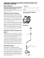
Illustration 4
Switch Circuit
c.Installation work and electrical wiring must be done by
qualified person(s) in accordance with all applicable codes
and standards, including fire-rated construction.
d.The combustion airflow needed for safe operation of fuel
burning equipment may be affected by this unit's operation.
Follow the heating equipment manufacturer's guidelines and
safety standards such as those published by the National
Fire Protection Association (NFPA), the American Society of
Heating, Refrigeration, and Air Conditioning Engineers
(ASHRAE) and the local code authorities.
e. When cutting or drilling into wall or ceiling, do not damage
electrical wires or other hidden utilities.
f. Ducted fans must always be vented to the outdoors.
g. Install fan at least five feet above the floor.
4. WARNING! Check voltage at the fan to see if it corresponds to the
motor nameplate.
Electrical Supply from
Breaker Panel