1
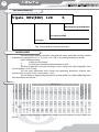
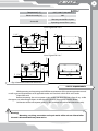
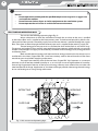
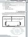
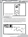
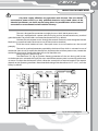
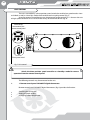
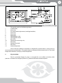
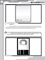
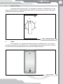
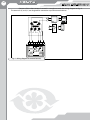
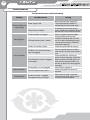
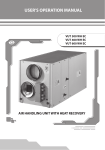
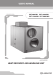
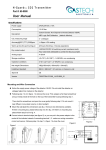
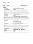
USER’S MANUAL
Heat (Energy)
Recovery Ventilator
Vents Frigate HRV 120 S
Vents Frigate ERV 120 S
2
Frigate HRV(ERV) 120 S
CONTENT
Introduction ...............................................................................................
Application ..................................................................................................
Delivery set ..................................................................................................
Unit designation key ................................................................................
Technical data .............................................................................................
Safety requirements .................................................................................
Structure and operating logic ..............................................................
Mounting and setting-up .......................................................................
Condensate drainage ..............................................................................
Connection to power mains ..................................................................
Unit control .................................................................................................
Servicing and maintenance ..................................................................
Troubleshooting ........................................................................................
Storage and transportation rules ........................................................
Manufacturer’s warranty ........................................................................
Acceptance certificate .............................................................................
Connection certificate .............................................................................
Warranty card .............................................................................................
3
3
3
4
4
5
6
7
8
9
10
15
16
17
17
18
18
18
3
INTRODUCTION
This user’s manual combines technical description, operation and service manual,
technical data sheet and installation guidelines for the heat (energy) recovery ventilator Vents Frtigate
HRV (ERV) 120 S, hereinafter referred to as the unit.
APPLICATION
The unit with heat (energy) recovery is designed to save thermal energy by means of heat
and energy recovery and is one of the energy saving components used in the buildings and premises.
The ventilator is a component unit and is not designed for independent operation.
The unit is designed to provide permanent controlled air exchange by mechanical
ventilation in houses, offices, hotels, cafés, conference halls and other residential and public premises
as well as utilization of extract air heat energy to warm up supply purified air.
The unit is for ceiling mounting and wall mounting (only for Vents Frigate ERV 120 S).
The unit is rated for continuous operation always connected to power mains.
Transporting medium must not contain any flammable or explosive mixtures, evaporation
of chemicals, coarse dust, soot and oil particles, sticky substances, fibrous materials, pathogens or any
other harmful substances.
The unit is not designed to be used by children, physically or mentally
disabled persons, persons with sensory disorder, persons with no appropriate
experience or expertise.
The unit can be operated by qualified experts after appropriate instruction
about its use and operation.
The unit shall be mounted in places inaccessible for children.
DELIVERY SET
Unit Vents Frigate HRV(ERV) 120 S User’s manual Packing box - 1 pce;
- 1 pce;
- 1 pce.
4
Frigate HRV(ERV) 120 S
UNIT DESIGNATION KEY
Frigate HRV(ERV) 120
S
Mounting design modification
S - suspended
Air capacity [CFM]
Unit type
HRV - Heat Recovery Ventilator
ERV - Energy Recovery Ventilator (enthalpy)
TECHNICAL DATA
The heat (energy) recovery ventilator is designed for indoor application with the ambient
temperature ranging from +34 °F (1 °С) up to +122 °F (50 °С) and relative humidity up to 80%.
Ingress Protection rating:
IP44 for the unit motors.
IP 22 for the assembled unit connected to air ducts.
The Vents Frigate HRV 120 S unit net weight is 53 lbs (24 kg); the Vents Frigate ERV 120 S
unit net weight is 51 lbs (23 kg).
The unit series designation, basic overall and connecting dimensions, external view,
technical data are shown in fig. 1 and in tables 1 and 2.
The unit design is regularly being improved, so some models can slightly differ from those
ones described in this manual.
Table 1
0,6”
(150 Pa)
0,7”
(175 Pa)
0,8”
(200 Pa)
0,9”
(225 Pa)
1,0”
(250 Pa)
1,2”
(300 Pa)
116
(55)
104
(49)
91
(43)
78
(37)
64
(30)
49
(23)
18
(8)
65
(31)
51
(24)
41
(19)
25
(12)
12
(6)
(-)
(-)
(-)
(-)
(-)
(-)
120V,
60Hz
table 2.
Sones
0,5”
(125 Pa)
127
(60)
Duct Dia.
0,4”
(100 Pa)
137
(65)
Efficiency of heat
exchanger, %
0,3”
(75 Pa)
143
(67)
<80%
0,2”
(50 Pa)
RPM
0,1”
(25 Pa)
2460.
150
(71)
1325
Max. Watts
Max. Amps
Volts
Speed
high
142 1.23
2.8
5”
67 0.98
<80%
low
HRV 120S, ERV 120S
Model
Airflow CFM (L/s)
0.4
The maximum allowable air parameters for the paper heat recovery core are stated in the
5
Table 2
-22º F...140º F (-30...+60 º С )
Temperature [º С]
Relative humidity [%]
80%
Warranty service life is 2 years
Service life
Operating service life is 5 years
5"
4"
7"
1 1/2"
11/16"
Vents Frigate HRV 120 S
10"
1/2"
5 1/16"
20 1/16"
23 1/8"
21"
24 7/8"
5 1/16"
10"
20 1/16"
1/2"
7"
5"
11/16"
Vents Frigate ERV 120 S
21"
24 7/8"
23 1/8"
Fig. 1 Overall and connection dimensions
Safety requirements
While operating and mounting unit fulfill the requirements of the present operation manual
as well as general requirements of all applicable codes and standards valid in USA and Canada.
Ground the unit!
Before connecting the unit to power mains make sure that the unit is free of any visible
damages or any other foreign objects inside the casing that can damage the impeller blades.
Connection of the unit to power mains by duly qualified and authorized electricians only!
Warning!
Mounting, servicing, connection and repair works of the unit are allowed after
the unit is disconnected from power mains.
6
Frigate HRV(ERV) 120 S
Do not!
• Do not operate the unit beyond the specified temperature range or in an aggressive
and explosive medium.
• Do not connect clothes dryers or similar equipment to the ventilation system.
• Do not operate the unit in the air and dust mixture environment.
STRUCTURE AND OPERATING LOGIC
The unit has the following operating logic (fig. 2):
Warm stale extract air from the room flows through the air ducts to the unit, is purified
in the extract filter and is supplied to the heat recovery core and exhausted outside by exhaust fan.
Clean cold air from outside is moved by supply fans to the unit where it is purified through the supply
filter. Then clean air flows through the heat recovery core and is supplied to the room by supply fan.
Thermal energy of warm extract air is transferred to clean intake fresh air and warms it up.
The extract and intake air flows are fully separated during heat recovery which excludes any transfer
of odors and pathogens to supply air. Heat recovery minimizes thermal energy losses, energy demand
and heating costs.
Both sensible thermal energy and latent moisture energy contained in the extract air are
transferred in the Vents Frigate ERV 120 S unit heat recovery core to the cold intake air flow from
outside to warm it up before supplying to the room.
The paper heat recovery core of the unit Vents Frigate ERV 120 S operates as a moisture
balancer in case of too low outdoor humidity or as an air dryer in case of high outdoor air humidity.
Due to high hygroscopic features of the heat and energy recovery core material the unit does not
need condensate drainage. Application of the heat exchanger provides decreasing thermal energy
losses and heating costs saving during cold season.
5
2
7
3
4
EXTRACT AIR
INTAKE AIR
SUPPLY AIR
EXHAUST AIR
1
Fig. 2. Unit structure and operating logic
6
8
9
7
1.
Supply fan with backward curved blades and maintenance-free motor with external rotor
and integrated thermal protection.
2.
Extract fan with backward curved blades and maintenance-free motor with external
rotor and integrated thermal protection.
3.
Plate cross flow heat recovery core (Vents Frigate ERV 120 S — paper heat recovery core,
Vents Frigate HRV 120 S — aluminium heat recovery core).
4.
G4 supply air filter.
5.
G4 extract air filter.
6.
Frost protection thermostat.
7.
Control block.
8.
Drain pan (for Frigate HRV 120 S only).
9.
Drain hose (for Frigate HRV 120 S only).
MOUNTING AND SETTING-UP
min 2”
While mounting the unit provide enough access for the unit maintenance and servicing.
Mount the unit to ceiling by means of the belts that are rigidly fixed to horizontal plane (fig. 3) or with
threaded rods fixed inside the dowels attached to the ceiling. The unit may be mounted to the wall
with a suspension bracket (fig. 4) that is fixed to the unit with three screws and dowels (only for the
unit Frigate ERV 120 S).
Fig. 3. Ceiling unit mounting example
8
Frigate HRV(ERV) 120 S
This installation example is applicable
only for Vents Frigate ERV 120 S
Fig. 4. Wall unit mounting
CONDENSATE DRAINAGE
The Vents Frigate HRV 120 S unit is equipped with a condensate drain hose for condensate
drainage (fig. 5). Connect the drain hose (1), U-trap (3) and drain system (5) with metal, plastic or
rubber pipes (2 and 4). The pipes must be sloped down at least by 3°. Before starting operation of
the unit fill the system with water and check that U-trap is always filled with water. Make sure that
the water drainage is correct, otherwise some condensate may be accumulated inside the unit and
provoke subsequent equipment damage and water ingress to the room. The condensate drainage
system is designed for operation at the ambient temperature above 32 ºF (0 °С). If the ambient
temperature is below 32 ºF (0 °С), insulate the drain system and provide air heating.
min 3°
4
5
1
2
3
fig. 5. Condensate drainage
9
Connection to power mains
Cut power supply off before any operations with the unit. The unit shall be
connected to power mains by a duly qualified electrician only. Rated values of the
electrical parameters are shown on the rating plate. Any modifications of the internal
connections are not allowed and will void the warranty.
The unit is designed for connection to single-phase ac 120 V / 60 Hz power mains.
The unit is equipped with a power cable and a plug and can be connected to any standard
grounded outlet. The power cable is connected to the terminal X1 by default.
Connect the unit to power mains through the external automatic switch integrated into the
fixed wiring system that breaks the circuit in case of short circuit or overload.
Install the circuit breaker to have a free quick access in case of need to turn the unit off
promptly.
The unit has overload protection provided by the thermal fuse which is activated in case of
overload or short circuit. To replace the thermal fuse, disconnect the unit from power mains, remove the
overload or short circuit. Remove the thermal fuse and check the unit.
Wiring diagram is shown in fig. 6.
The thermostat TS1 (fig. 6) provides freezing protection of the unit during cold season.
As the thermostat is activated, the supply fan stops and the heat recovery core is warmed up with extract
air stream. To adjust the thermostatic switch, rotate the control dial to required setpoint. The setpoint
depends on the operating conditions. Recommended setting of the thermostat is 37°F (+3ºС), set in the
factory by default.
Х1
9
W1
White
120V 60Hz
L
N
РЕ
SW2
Low
Stand by
Med
Black
Green
Setup of Med
Setup of Low
2
10
TR1
White
White
Red
Red
~120V
~24V
2
11
Х2
Х3
1
2
3
4
~24V 5
PE 6
Х6.2
Х6.1
Х4
Х5.2
Low
Med
G0
High
Х5.1
К1
К2
К3
1 Kon 1
2 Kon 2
3 PE M1
4 PE M2
5 Brown M1
6 Cap1
7 Cap1
8 Black M1
9 Black M2
10 Cap2
11 Cap2
12 Brown M2
13 Blue M1
14 Term
15 Term
16 Blue M2
1
3 2
3
4
Y/G
Y/G
5
SW1
16
6
12
17
18
19
8
7
14 C
15 2
13
Сap1
Сap2
t
0
М1
FAN MOTOR
М2
FAN MOTOR
TS1
Two wire
control
11
2
termostat
1
9
10
Fig. 6. Unit wiring diagram
10
Frigate HRV(ERV) 120 S
UNIT CONTROL
The unit is controlled by a three-position speed switch that enables low-speed modes «Low»
and «Med» as well as «Stand by» mode which enables total air quality control (fig. 7).
Up to five external control devices may be connected to the terminals 2-11 that turn the unit
to high-speed ventilation in case of activation of any of the control devices (fig. 6).
Terminals for
connection of the
remote control panel
Three-speed switch
Fig. 7. Unit control
Switch the three-position speed controller to «Standby» mode for correct
operation from the remote control panel.
The following controls may be connected to the unit:
1.
1. Remote control panel SAS908PIT digital thermostats
Remote control panel SAS908PIT digital thermostats (fig. 8) provides the function:
Switching the unit on/off;
Setting required air flow;
Displaying indoor temperature.
11
Fig. 8 Control panel SAS908
1.
2.
3.
4.
5.
6.
7.
8.
9.
10.
11.
12.
13.
14.
The control panel has the following buttons:
On/off button;
Not active;
Fan speed control adjustment (auto/high/med/low);
Not active;
Not active;
Not active;
Heating power scale;
Heating power value;
Not active;
Temperature measuring unit;
Not active;
Selected fan speed;
Not active;
Indoor temperature.
To turn the unit on/off press the button (1). Required fan speed (air flow) is set by means by
consecutive pressing the button 3. The speed settings are displayed on the control panel, 12. The indoor
temperature indicator (14) displays indoor temperature.
2. CO2 transmitter
The CO2 transmitter Tongdy CO2 (fig. 9) is designed for use in offices and other public
premises. It switches fans to higher speed as CO2 indoor concentration exceeds setpoint.
12
Frigate HRV(ERV) 120 S
Fig. 9. CO2 transmitter
3. Humidistat
The humidistat (fig. 10) is used for indoor humidity control. If the indoor humidity exceeds
the setpoint, the humidistat switches the ventilation to high-speed mode. The unit operates in highspeed mode until humidity drops to setpoint. Adjust the humidity setpoint if required.
Check that the humidistat closes contact if indoor humidity exceeds the
setpoint and breaks contact if the indoor humidity is below the setpoint.
30%
40%
20%
10%
off
Fig. 10. Humidistat
max
13
4. Mechanical timer
The remote mechanical timer (fig. 11) is designed for installation in pollutable areas. As the
timer is activated the unit is switched to high-speed mode. You can connect up to 5 timers in the premise
at 500 feet (152 m) distance to the unit.
OFF
60
10
50
20
40
Fig. 11. Mechanical timer
5. Switch
The switch (fig. 12) is designed for indoor installation in pollutable areas. As the switch is
activated and the contacts are closed, the unit is switched to high-speed ventilation mode. To reset the
unit to continuous low-speed operation press the switch to break the contacts.
OFF
ON
Fig. 12. Switch
14
Frigate HRV(ERV) 120 S
Connect all the above external controls in compliance with the wiring diagram in fig. 13.
The terminals (2) and (11) are designed for connection up to five control devices.
30%
40%
20%
10%
off
OFF
OFF
60
10
50
40
20
ON
1
2
6
9
10
Fig. 13. Wiring diagram for external controls
11
max
15
SERVICING AND MAINTENANCE
Servicing of the unit is required 3-4 times per year. Besides general cleaning, the following
operations are required:
1.
Filter maintenance (3-4 times per year)
Dirty filters increase air resistance in the system and reduce supply air flow to
the premises.
Clean or replace the filters as often as required, but at least 3-4 times per year.
Clean the filter with running water or a vacuum cleaner.
After two cleaning replace the filter. Contact your local supplier for new filters.
2. Heat recovery core maintenance (once per year)
Some dust can get accumulated on the heat recovery core block even if you clean or replace
the filters regularly in compliance with above procedure. To maintain the high heat exchange efficiency,
regular cleaning is required.
To clean the paper heat and energy recovery core of the unit Vents Frigate ERV
120 S, pullt it out of the unit and clean it with a vacuum cleaner. Do not use water, sharp objects, abrasive
detergents and aggressive solvents to prevent the heat recovery core damage. Make sure that the heat
and energy recovery core is dry and re-install it back inside the unit.
To clean the aluminium heat recovery core of the unit Vents Frigate HRV 120 S,
pull it out of the unit and clean the heat recovery core with warm detergent solution. Make sure that the
heat recovery core is dry and re-install it back inside the unit.
3. Fan maintenance (once per year)
Even if you perform regular maintenance of the filters and the heat recovery core, some dust
and grease can get accumulated inside the fans and reduce the fan performance and supply air flow.
Clean the fans with a soft brush or dry cloth. No water and abrasive detergent, sharp objects
or solvents are allowed for cleaning to prevent the impeller damage.
4.
Condensate drainage system maintenance (once per year)
The drain hose can get clogged with the extracted particles. Clean the drain hose is required.
Check proper functioning of the drain system by pouring some water into the drain pan at the unit
bottom. Clean the U-trap and the drain tubes if required.
5.
Supply air flow inspection (twice per year)
Leaves and other objects can clog the intake grille and decrease the unit performance and
supply air flow. Check the intake grille twice per year and clean it if required.
6.
Air ductwork maintenance (once in 5 years)
Even if you fulfill all the above maintenance guidelines regularly, a certain amount of dust is
accumulated inside air ducts. That reduces the ventilation system performance. Clean or replace the air
ducts periodically.
16
Frigate HRV(ERV) 120 S
Troubleshooting
Possible malfunctions and fault handling
Problem
Possible reasons
Power supply is off.
The fan(s) do(es) not
start running.
Thermal fuse is melted.
The extract filter is clogged.
Cold supply air.
The heat recovery core is frozen.
Too low set rotation speed.
The filters, fans or heat recovery
core are clogged.
Low air capacity.
The ventilation system is clogged
or damaged.
The impeller(s) is (are) clogged.
Noise, vibration.
Water leakage
Fan screw tightening is loose.
The drain system is clogged,
damaged or wrong arranged.
Solving
Make sure the power supply line
is connected correct, otherwise
troubleshoot the connection error.
Disconnect the unit from power
mains. Remove the overload. Replace
the thermal fuse and check the unit.
Clean or replace the extract filter.
Check the heat recovery core
condition. Shutdown the unit and
turn it on after the freezing danger
is no longer imminent. Check the
thermostat setpoints.
Check the speed control settings.
Clean or replace the extract filters;
clean the fans and the heat recovery
core.
Check the diffusers and louvre
gravity shutters opening, check the
exhaust hood and intake grille and
clean those if required; make sure
that the air ducts are not clogged or
damaged.
Clean the fan impeller(s).
Check and tighten the screws if
required.
Clean the drain pipe is required.
Check the drain pipe slope, U-trap
and temperature conditions.
17
STORAGE AND TRANSPORTATION RULES
Store the unit in the manufacturer’s original packing box in a ventilation premise with the
temperature range from +14 °F (-10 °С) up to +104 °F (+40 °С) and relative humidity less than 60%
(at +68 °F (+20 °С)). Vapors or particles which can cause corrosion or damage the insulation or connection
tightness are not allowed in the stock. Use hoist equipment for loading and storage operations to
prevent the unit falling or excessive oscillation.
Transportation with any vehicle type is allowed provided that the goods are protected
against mechanical and weather damage.
Manufacturer’s warranty
Manufacturer hereby guarantees normal performance of the unit within 2 years since the
date of its sale in accordance to the rules of transportation, storage, assembling and operation. In case of
no confirmation of sales date the warranty period is calculated from the production date.
In case of any unit operation malfunctions during the warranty period the manufacturer
accepts any claims from the Customer if the technical certificate with detailed description of the
malfunction is provided.
The unit damage as a result of any unauthorized modifications of the electric circuit is not a
warranty case.
Both warranty and post-warranty services for the unit are provided at the manufacturing
facility. For warranty and post-warranty services contact your seller or the product manufacturer.
RECLAMATIONS AND CLAIMS FOR REPLACEMENT SHALL NOT BE ACCEPTED WITHOUT
A COMPLETED CONNECTING CERTIFICATE.
18
Frigate HRV(ERV) 120 S
ACCEPTANCE CERTIFICATE
Acceptance certificate
The heat (energy) recovery ventilator
VENTS Frigate HRV(ERV) 120 S
is recognized serviceable and compliant with the technical parameters.
Stamp of the acceptance inspector Date of production _____________________
Sold by
Name of the vendor, stamp of the shop __________________________________________________
___________________________________________________________________________________
Sale date ______________________________
CONNECTION CERTIFICATE
This is to certify that the heat (energy) recovery ventilator VENTS Frigate HRV(ERV) 120 S
has been connected to power mains pursuant to the requirements stated in this User’s Operation
Manual by the electrical engineer:
Company name: _____________________________________________________________________
Electrical engineer name: ______________________________________________________________
Date _____________________________ Signature _________________________________________
Warranty card
19