1
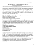
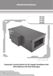
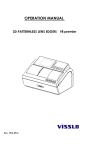
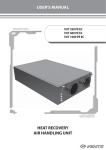
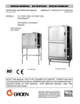
USER’S OPERATION MANUAL
VUT 300 WH EC
VUT 400 WH EC
VUT 600 WH EC
AIR HANDLING UNIT WITH HEAT RECOVERY
2
VUT .. WH ЕС
Content
Introduction
Use
Delivery set
Structural designation key
Technical data
Safety requirements
Structure and operating logic
Mounting and set-up
Condensate drainage
Connection to power mains
Unit control
Functional diagram
Technical maintenance
Fault handling
Storage and transportation rules
Manufacturer’s warranty
Acceptance certificate
Electrical connection certificate
Warranty card
3
3
3
4
4
7
8
9
12
13
14
25
26
27
28
28
29
29
29
3
INTRODUCTION
The present user’s operation manual contains technical description, data sheet, installation and
mounting guidelines for the air handling unit with heat recovery VUT WH EC, VENTS series (hereinafter
referred as the unit).
USE
The unit is designed to save thermal energy by means of heat recovery and is one of the energy
saving components used in buildings and premises.
The units with heat recovery and water heater are designed to provide permanent controllable
air exchange by mechanical ventilation in houses, offices, hotels, cafés, meeting halls and other
mechanically ventilated premises as well as utilization of extract air heat energy to warm up supply
purified air.
The system is designed to enable considerable energy saving. It has the function of automatic
heat exchange and ventilation mode which is set by automatic ventilation mode.
The unit is equipped with a water heater for further
The unit is a component unit and is not designed for independent operation.
Transporting medium must not contain any flammable or explosive mixtures, evaporation of
chemicals, coarse dust, soot and oil particles, sticky substances, fibrous materials, pathogens or any
other harmful substances.
The unit is not designed to be used by children, physically or mentally disabled
persons, persons with sensory disorder, persons with no appropriate experience or
expertise.
The unit can be operated by qualified experts after appropriate instruction about its
use and operation.
Install the unit to be out of reach of children.
DELIVERY SET
Unit
Remote control panel User’s operation manual
Packing box
- 1 pce;
-1 pce;
-1 pce;
- 1 pce;
4
VUT .. WH ЕС
STRUCTURAL DESIGNATION KEY
VUT XXX
X
W
H
ЕС
Motor type
EC - electronically commutated
motor
Spigot orientation
H - horizontal
Heater type
W - water heater
Modification (spigot Ø)
1 -150 mm, 2 - 160 mm
Air capacity [m3/h]
Unit type
VUT - ventilation with energy utilization
TECHNICAL DATA
The unit is designed for indoor application with the ambient temperature ranging from +1°C up
to +40°C and relative humidity up to 80%.
Ingress Protection (IP) rating from solid objects and liquids:
IP 44 for the unit motors;
IP 22 for the assembled unit connected to the air ducts.
The unit overall and connecting dimensions, external view, technical data are shown in fig. 1 and
in table 1.
The unit design is regularly being improved, so some models can slightly differ from those ones
described in this manual.
1198
1092
88
231
127
249
1137
Fig. 1. Unit overall and connecting dimensions
403
500
D
5
Table 1
VUT 300-1
WH ЕС
Type
VUT 300-2
WH ЕС
VUT 400
WH ЕС
VUT 600
WH ЕС
Voltage, 50 Hz [V]
1 ~ 230
Max. fan power [W]
2 items x 70 2 items x 70 2 items x175 2 items х 175
Max. fan current [A]
2 items х 0,6 2 items х 0,6 2 items х 1,3 2 items х 1,3
Number of heating coils
2
Total unit power [W]
0,14
0,35
Total unit current [A]
1,2
2,6
Max. air capacity, m3/h
300
300
400
550
Rotation speed [min -1]
1380
1380
1340
2150
Noise level, 3 m [dB(A)]
24-45
Max. transporting air temperature [°C]
28-47
from -25 up to +60
Casing material
Aluzinc
Insulation
25 mm mineral wool
Filter:
extract
G4
supply
F7 (EU7)
Connected duct diameter [mm]
Weight [kg]
Ø150
Ø160
Ø200
Ø200
40
Heat recovery efficiency
up to 90%
Heat exchanger type
Counter-flow
Heat exchanger material
Polystyrene
The basic thermal dynamic characteristics of the water heaters are stated in the performance
charts, fig. 2.
6
VUT .. WH ЕС
VUT 300 WH EC, VUT 400 WH EC
Coil heating capacity [kW]
Water pressure drop [kPa]
External air temperature [°C]
Air temperature after heater [°C]
Air flow through the heater [m3/h]
Water flow through the water heating coils [l/s]
Water heater parameters calculation example:
Supply air temperature. Prolong the line (1) of air flow (300 m3/h) up to the point where it crosses the outside air temperature (blue curve), e.g. -20°C; then draw a horizontal line (2) from this point to the
left till crossing water in/out temperature curve (90/70). From this point draw a vertical line (3) to the supply air temperature axis on top of the graphic (+18 °C).
Heating coil capacity. Prolong the line (1) up to the point where it crosses the outside air temperature -20°C (red curve) and draw a horizontal line (4) from this point to the right until it crosses water in/out
temperature curve (90/70), from here draw a vertical line (5) up to the scale representing the heating coil capacity (4.75 kW).
Water flow. Prolong the line (5) down to water flow axis at the bottom of the graphic (6) (0.72 l/s).
Water pressure drop. Draw the line (7) from the point where line (6) crosses the black curve to the pressure drop axis. (3.5 kPa).
VUT 600 WH EC
Coil heating capacity [kW]
Air flow through the heater [m3/h]
Water flow through the water heating coils [l/s]
Water heater parameters calculation example:
Supply air temperature. Prolong the line (1) of air flow (400 m3/h) up to the point where it crosses the outside air temperature (blue curve), e.g. -20°C; then draw a horizontal line (2) from this point to the
left till crossing water in/out temperature curve (90/70). From this point draw a vertical line (3) to the supply air temperature axis on top of the graphic (+18 °C).
Heating coil capacity. Prolong the line (1) up to the point where it crosses the outside air temperature -20°C (red curve) and draw a horizontal line (4) from this point to the right until it crosses water in/out
temperature curve (90/70), from here draw a vertical line (5) up to the scale representing the heating coil capacity (5.9 kW).
Water flow. Prolong the line (5) down to water flow axis at the bottom of the graphic (6) (0.075 l/s).
Water pressure drop. Draw the line (7) from the point where line (6) crosses the black curve to the pressure drop axis. (5.1 kPa).
Fig. 2 Calculation of water heater parameters
Water pressure drop [kPa]
External air temperature [°C]
Air temperature after heater [°C]
7
SAFETY REQUIREMENTS
While operating and mounting the unit consider the requirements of the present operation
manual as well as general requirements of all applicable local and national building and electrical
codes and standards.
The unit must be grounded!
Before connecting the unit to power mains make sure that the unit is free of any visible damages
or any other foreign objects inside the casing that can damage the impeller blades.
Mounting, wireworks and connection to power mains only by duly qualified electricians with
valid electric work permit!
Do not operate the unit beyond the specified temperature range or in an aggressive and explosive
medium!
The unit is not rated for use in areas where atmospheric conditions are determined by sea climate
or hot springs or in media where air is deodorized and supplied further to other premises.
Disconnect the unit from power supply prior to any mounting, servicing, connection
or repair operations with the unit.
•
•
•
Do not!
Do not operate the unit beyond the specified temperature range or in an aggressive
and explosive medium!
Do not connect clothes dryers or similar equipment to the ventilation system!
Do not operate the unit in the air and dust mixture medium!
8
VUT .. WH ЕС
Structure and operating logic
The unit has the following operating logic (fig. 3):
Warm stale extract air from the room flows through the air ducts to the unit, is purified in the
extract filter and is supplied to the heat exchanger and exhausted outside by exhaust fan. Clean cold
air from outside is moved by supply fans to the unit where from it is directed to the supply filter. Then
cleaned air flows through the heat exchanger and is supplied to the room along air ducts.
Thermal energy of warm extract air is transferred to clean intake fresh air from outside and
warms it up. Heat recovery minimizes thermal energy losses, energy demand and operating costs for
climatization accordingly.
Extract air
Intake air
Supply air
Exhaust air
Fig. 3. Unit operating logic
The unit is a framework construction that includes a frame made of sis rigidly fixed 25 mm thick
sandwich panels. The three-layer sandwich panels are made of two galvanized sheets, internally filled
with thermal- and sound-insulated layer.
The fig. 4 shows the unit design. The unit is equipped with quick-detachable service panels 14 for
scheduled repair and maintenance operations. The panels are specially sealed. The terminal box 15 is
detached to inner side of one of the side walls 13.
The terminal box incorporates a terminal block with the wires from the control block. While
connecting the unit to power mains route the wires though the screwed cable glands. The terminal
box inner side shows a wiring diagram for the unit connection.
The unit basic modification includes:
The remote control panel 9 is connected to the control system inside the unit casing
though the data cable;
Two single-inlet centrifugal fans, a supply 1 and an extract 2 fan with forward curved
blades and maintenance-free motors with external rotor and integrated overheating protection;
Plate counter-flow heat exchanger 3.
One water heater compatible with a threaded pipe G ¾.
Two filters: supply filter 4 with F7 filter class and extract filter 5 with G4 filter class. The
supply filter prevents dirt ingress from outside air to the room and protects the unit inner parts from
soiling. The extract filters protect the unit parts from soiling.
Some condensate may appear during heat recovery. Condensate is collected in the drain pan and
removed from the unit through the drain pipe 6.
9
1. Supply fan;
2. Extract fan;
3. Plate counter-flow heat
exchanger
4. Supply filter;
5. Extract filter;
6. Drain pipe;
7. Water heater;
8. Bypass;
9. Remote control panel;
10. Control block casing;
11. Condensate drain pan;
12. Data cable;
13. Side walls;
14. Quick-detachable panesl.
15. Terminal box.
Fig. 4. Unit design
MOUNTING AND SET-UP
The unit is suspended to the ceiling on the threaded rod that is fixed inside the dowel or may be
rigidly fixed on a level surface (fig. 5).
a) Suspended unit mounting
Example 1
Example 2
Washer
Nut
Washer
Nut
Nut
Antivibration rubber
Washer
Antivibration rubber
b) Unit mounting on a horizontal plane
Nut and
counter-nut
Fig. 5. Unit mounting
10
VUT .. WH ЕС
Mount the unit on a rigid and stable structure. Check the technical parameters and the unit
weight.
Use bolts to suspend the unit to the ceiling. Make sure that the construction has sufficient load
capacity to carry the unit weight. Otherwise reinforce an installation place by beams etc. After that fix
the bolts. If the construction strength or surface is not rigid enough it can resonate with the unit and
create abnormal noise and vibration.
While mounting the unit provide enough service space and an access door in the ceiling for
inspection and maintenance of the filters, heat exchanger and fans. One access door is required for
each unit.
Make sure that the ambient conditions match the unit operation requirements before starting
any installation works.
The operating temperature for the unit ranges between +1°C and +40°C for dry bulb thermometer
at relative humidity 80%.
If the bolts used for the unit mounting are too short the unit can generate abnormal noise and
resonate with the ceiling.
Use longer bolts with to prevent resonance.
Use longer bolts with to prevent resonance. If the connection point to the spiral seam duct is
supposed to be the source of the abnormal noise, install a flexible air duct instead of the flexible one.
For the better effect you may use anti-vibration connectors.
Make sure of no foreign objects inside the casing before installation. Preinstall M8 anchor bolt.
Then insert the anchor bolt inside the mount for the fixing bracket and fix it with nuts and washers.
While mounting the unit provide enough minimum distances for accessing the unit for its
servicing and maintenance. The minimum distance from the unit to the wall is shown in fig. 6.
Minimum distance for accessing the unit
Control blocks mounting place
Fig. 6. Minimum distance for accessing the unit
11
To attain the best performance of the unit while mounting provide a straight 1 m duct section on
both sides of the unit.
If the unit is installed at the air duct inlet or outlet it shall be equipped with a grille with the mesh
width up to 12.5 mm or any other protecting device to prevent free access to the unit fans.
To increase the unit efficiency connect the water heating coils counter-flow (fig. 7).
All the stated calculations are valid for counter-flow connection of the water heater. The water
heater connected on counter-flow basis has lower capacity but higher frost-resistance.
a) Direct flow connection
b) Counterflow connection
wa
ter
ou
tle
t
wa
ter
inl
et
wa
ter
ou
tle
t
wa
ter
inl
et
Fig. 7. Water heater connection
Mixing unit diagram (not included into delivery set) of the water heater is shown in fig. 8.
1
2
2
1.
2.
3.
4.
5.
6.
7.
8.
Mixing unit diagram
3
4
6
M
7
5
8
Water heater
Shutoff valves
Circulation pump
Bypass damper
Boiler
Heat medium regulating valve
Non-return valve
Coarse filter
Heat medium regulating valve actuator
Fig. 8. Mixing unit diagram
12
VUT .. WH ЕС
Сirculation pump operation (not included into delivery set).
The circulation pump switches automatically on both in summer or winter mode when the fans
are started or at the beginning of the water coils preheating procedure and switches off as the fans
stop.
In case of water coil freezing danger no matter of the active summer/winter mode, the circulation
pump turns on. After the freezing danger is no longer imminent and after the alarm reset the
circulation pump reverts to the previous operation mode.
Bypass operation.
The heat exchanger is equipped with a temperature sensor to control the bypass damper position
to prevent its freezing. In case of the heat exchanger freezing danger, the bypass damper installed
on the supply side is opened to let supply air flow through the bypass air duct and extract air flow
through the heat exchanger to warm up a frozen surface. After defrosting and exhaust air temperature
increase the bypass air duct is closed and supply air flows again through the heat exchanger.
CONDENSATE DRAINAGE
Connect the condensate drain pipes 1, U-trap 3 (not included into delivery set) and the drainage
system 5 with metal, plastic or rubber pipes 2 and 4. The tubes must be sloped down by min. 3 °. 1 m pipe
must be sloped down by 55 mm. Before starting the unit fill the system with water and check that U-trap
is always filled with water. Make sure that the water drainage is correct. Wrong connection to drainage
system may result in condensate accumulation and outflow to the premise .
The condensate drainage system is designed for operation at the ambient temperature above 0 °C.
Do not connect several drain pipes from several air handling units to one U-trap!
Direct condensate outside without connection to drain system is not allowed!
Type
1. Drain pipe
2. Connecting pipe
3. U-trap
4. Drain pipe
5. Sewage system
Fig. 9. Condensate drainage
А (mm)
В (mm)
VUT 300 WH ЕС
140
70
VUT 400 WH ЕС
190
95
VUT 600 WH ЕС
140
70
13
CONNECTION TO POWER MAINS
Connection of the unit to power mains is allowed by a qualified electrician with a
work permit for the electric units up to 1000 V after detailed study of the present user’s
manual.
The rated electrical parameters of the unit are shown on the rating plate. Any
internal connection modifications are not allowed and void warranty.
The unit is rated for connection to single-phase ac 230 V / 50 Hz.
Connect the unit to power supply by means of insulated, durable and thermal-resistant cords (cables,
wires) with respective cross section, in any case no less 2.5 mm2.
However, the given section value is tentative. The choice of the required wire section in each case
shall be based on the wire type, its maximum permissible heating temperature, its insulation, length
and installation method.
Use copper wires only.
Connect the unit to power mains through the terminal block in the junction box in compliance with
the wiring diagram, fig. 10 and the terminal marking.
Connect all the control and supply cables in compliance with the terminal marking!
Connect the unit to power mains through the external automatic thermal-magnetic circuit
breaker integrated into the fixed wiring system. The trip current must be in compliance with current
consumption, refer table 1.
Cadet Mini
Power 230 V AC
VUT .. VH ЕС
1. The unit comprises P1 only.
2. * - Connection option depending on the control panel type
3. ** - Max. wire length from the unit to the panel is 20 m!
4. *** - Cable length from remote control panel must not exceed 10 m!
Electric shock hazard!
Design.
Name
Circulation pump
Supply air damper actuator
Extract air damper actuator
Heat medium regualting valve actuator
Contact from fire alarm panel
Remote control panel
Type
Wire***
mm
mm
mm
mm
mm
Fig. 10. External wiring diagram
14
VUT .. WH ЕС
Recommended rated current of the circuit breaker is 6.3 A. To connect the unit to power mains
route the power and ground cables through the cable screws gland.
The mounting place of the automatic circuit breaker must ensure a quick access for alarm
switching off if required.
UNIT CONTROL
General description of the automatic control system.
The unit is equipped with a built-in electronic control and automatic block (refer item 4 on fig. 11)
and the remote control panel (fig. 14).
The automatic control system has the following functions:
1. Switching the unit ON/OFF;
2. Maintaining set supply temperature by means of actuating the heat medium regulating valve;
3. Water heater freezing protection according to TS1 thermostat installed downstream from the
water heating coils and according to return heat medium sensor;
4. Actuating the heat exchanger bypass damper;
5. Control and monitoring of the external circulation pump;
6. Heat exchanger freezing protection;
7. Control and monitoring of the supply and extract fans;
8. Actuating supply and exhaust air dampers;
9. System shutdown on signal from fire fighting system.
1. Extract filter
2. Heat exchanger
3. Supply filter
4. Electronic control block
5. Water heater
6. Extract fan
Fig. 11. Location of the electronic control block
15
Structure and operating logic of automatic control system:
Automatic control system has winter and summer operation modes. The mode is selected
automatically depending on the outside temperature: if the outside temperature is above the set
point (0°C by default) the system operates in summer mode. If the temperature drops below this set
point the system automatically switches to winter mode.
Basic system functions in summer mode:
-
maintaining set supply air temperature level by means of controlling the heater regulation
valve;
-
closing of the heater regulation valve and external air dampers during the fan shutdown.
Extra system functions in winter mode:
-
maintaining the set supply air temperature level by means of controlling the heat medium
regulation valve;
-
preheating of the water coils before the fan start-up within the time period set by PLC
( parameter Q-02, factory setting 180 seconds, see table 3 by means of 100% opening the heater
regulation valve to provide full air stream through the heating coils. This function is disabled by
default, the factory setting is OFF. It is activated from the PLC, parameter Q-14, see table 2.
-
maintaining set minimum return water temperature level when the fans are turned on.
This level is set from the PLC menu, parameter Q-01 (refer the table 2), the default setting is +20°C.
Both in winter and summer modes, the control system enables freezing protection of the water
coils by the thermostat TS1 installed downstream from the heating coils.
In case of freezing danger the fans are turned off, the external air dampers are closed and the
heat medium regulating is 100% opened to enable full stream of heat medium through the coils. The
circulation pump is started.
The control system has extra option to restart the fans after power failure. This option is activated
and adjusted from the controller menu.
16
VUT .. WH ЕС
The air handling unit is equipped with an electronic control block, fig. 11, 12.
F1
F2
TE3
Z1
TR1
TS1
X1
F1 - thermal fuse
F2 - thermal fuse
TE3 - return heat medium sensor
TR1 - transformer 230 VAC / 24 VAC
X1 - terminal box for external connections
Z1 - digital controller
TS1 - freezing protection thermostat
Fig. 12. Electronic control unit
The digital controller is the basic component of the control system, fig. 13.
F1
L1
F2
L2
Power Alarm
Fig. 13 Digital controller
Fault
CADET mini
Esc
Enter
17
The controller has the following controls and indicators:
Indicator;
Buttons;
LED-lights.
Indicator − LCD display with illumination. The display shows all the online operating
parameters, temperatures, set points and alarms;
Buttons − 6 buttons on PLC panel designed for the following functions:
Esc − move one level up in a list; exit parameter editing;
Enter − move one level down in a list for function selection; enter edit mode; save edited
set point.
− reduce the set point value; move to the previous parameter in a list;
− increase the set point value; move to the next parameter in a list;
F1, F2 − controller service buttons.
LED lights:
Power − PLC power supply indicator;
Alarm − Alarm in the system;
Fault − PLC alarm;
L1 − not activated;
L2 − not activated;
Selecting the required function:
Select the required function using the buttons and , then press Enter. Press Esc to return
back to the list of functions.
Modifying set value:
Select the required parameter using the buttons and , then press Enter. Use the same buttons
to edit the parameter, i.e. to increase or decrease it . The editing value is blinking. Press Enter to save it.
To exit without changes press Esc. The editable values are enclosed in brackets “ >< “.
The controller engineering parameters (factory settings) are editable only after
entering the engineer password. Other parameters can be edited without entering the
engineering password.
The menu tree description is shown in the table 2. The factory setting column shows the set
parameters supplied as a standard.
18
VUT .. WH ЕС
Table 2
Menu tree
Factory setting
Functions and parameters, effects
Online parameters (online pram-s)
Online system parameters
Online temperatures (online temper-s)
Online temperature sensor reading menu
ТЕ1
Intake air temperature
ТЕ2
Exhaust air temperature
ТЕ3
Return heat medium temperature
ТЕ5
Supply air temperature
ALARMS
System alarm codes. Failure (1) or no failure (0)
Е1
Breakdown or short circuit of the intake air temperature sensor. Both
fans are stopped.
Е2
Breakdown or short circuit of the exhaust air temperature sensor. Both
fans are stopped.
Е3
Breakdown or short circuit of the return heat medium sensor. Both
fans are stopped.
Е5
Breakdown or short circuit of the supply air temperature sensor. Both
fans are stopped.
F1
F1 alarm (heat exchanger freezing) appears if exhaust air temperature
remains below R-02 parameter within R-03 time period, refer heat
exchanger adjustments Adjust-Recuper. In case of this alarm the
bypass damper is fully opened and the supply and extract fans keep
operating.
О1
Emergency system shutdown on the signal from fire fighting system.
Both fans are stopped.
U1
U1 alarm (water heating coils danger) appears if air temperature
downstream from the water heating coils drops below the minimum
set level +3 ºС.
U2
Alarm U2 (low return heat medium temperature) appears if the return
heat medium temperature drops below the set critical set point Q-04.
In case of any freezing danger alarms both fans are stopped, the
heat medium regulating valve is 100% opened and the circulation
pump turns on. Start-up of the fans at any freezing danger alarms is
disabled. The system can be restarted only after the above alarms are
no longer imminent, i.e. after the temperature of return heat medium
TE3 (for U2 alarm) and the air temperature at outlet from the water
heating coils (for U1 alarm) increases above the set point to prevent
the heating coils freezing.
19
Failure U3 (underheating) appears if return heat medium temperature
at the end of the heating cycle in winter mode before the fan start-up
is below the set point, factory setting +40°C. Start-up of the fans is
disabled.
U3
Adjustment
Basic controller adjustment menu. Adjustment editing by
professionals only! Editing by unauthorized unskilled labour may
result in the controller non-serviceability or malfunction. The
adjustment menu is password protected. Password information is for
professional installers and service engineers only.
Passw
The adjustment enter password is 1111 by default. To enter the
password which is displayed as “****” select the first number with
buttons and and press Enter, then enter the second number
with buttons and then press Enter and so on. After entering the
last number press Enter to get to adjustment menu. The engineering
menu is displayed, (Eng. adjust.)
Adjustment of fans (Adjust-vent)
V-02
Fan parameter adjustment menu
40
Supply fan low speed adjustment [%]
V-03
70
Supply fan medium speed adjustment [%]
V-04
100
Supply fan high speed adjustment [%]
V-05
40
Extract fan low speed adjustment [%]
V-06
70
Extract fan medium speed adjustment [%]
V-07
100
V-08
Enables (yes)
Pump adjustment (Adjust-pump)
H-01
H-02
20
Enabled (yes)
Extract fan high speed adjustment [%]
This parameter enables/disables fan start-up after power supply
failure. Disable function (no) disables the fan start-up after the power
supply failure and enable function (yes) enables the fan start-up after
the power supply failure;
Adjustment menu for circulation pump of the water heater.
Minimum operating time of the circulation pump [s].
This parameter enables/disables the circulation pump operation in
summer mode. Disable function (no) disables the pump start-up in
summer mode and enable function (yes) enables the pump start-up
when the heat medium regulating valve is activated.
20
VUT .. WH ЕС
Additional adjustments
Date/time
Additional controller adjustment menu
Day and time in adjustment menu
Date
Date adjustment menu
Тime
Time adjustment menu
Correct time
0
PLC timer correction factor per month. If the PLC timer is too fast
or too low, adjust the timer respectively by means of adjusting the
miscoordination time per month. Set the coefficient in seconds
with minus mark if the controller timer is too fast or plus mark if the
controller timer is too slow.
Change
password
2222
Use this function to edit the engineering password. To change the
password (which is shown as “****”) select the first number with
buttons and and press Enter, then enter the second number
with buttons and , then press Enter and so on. To return to the
previous digit entry press Esc. After entering the last number the PLC
saves the new password. From now on every time when you enter
the engineering menu enter the new password. Note: In case of PLC
adjustments reset (refer Eng. Adjust., reset) the engineering password
is set as 2222.
Light
Auto
PLC lighting mode. The LCD display illumination is off after some time
period provided that no button were pressed (“Auto” mode) or is on
all the time (“ON” mode).
Adjustment interface
Interface parameter
Protocol
UNIV.
Communications protocol. ModBus or UNIV value is available.
Speed
38,4
Data transfer speed
Devices
126
The number of devices in the network
Number
4
PLC number in the interface network.
Engineering menu
(Engineering adjustment).
Engineering menu contains engineering adjustments protected by
the engineering password (2222 by default).
21
Water heater adjustment
(Adjust-heater)
Water heater adjustment menu.
Q-01
20
Return heat medium temperature in winter mode when the fans
are turned off that is kept automatically at set level by means of
actuating the heat medium regulating valve [°C].
Q-02
180
Time period for air heating coil preheating [s]. During this period the
heat medium regulating valve is fully opened, the pump is turned on.
Q-03
40
Return medium temperature at the end of the heating cycle [°C] . If
the return medium temperature is below Q-03, the fan start-up is
disabled and U3 alarm is generated (refer Alarms, U3 code).
Q-04
5
Minimum return heat medium temperature to detect the water
heating coils danger [°C]. If the return heat medium temperature
drops down below Q-04, the heating coil freezing protection is
activated (refer Alarms, U2 code).
Q-05
0
Winter/summer mode switching temperature [°C]. The unit switches
automatically to summer or winter operation mode if the outside
temperature is above or below the Q-05 set point.
Q-07
180
Time period to reset the water coils freezing failures [s]. If automatic
alarm reset is enabled and any freezing danger appears, the fans are
restarted if they were operating before the alarm after Q-07 set time
period provided that the alarm is removed.
Q-08
2
Adjustment of supply air temperature regulation parameters by
the heat medium regulating valve - PI-regulation proportionality
constant.
Q-09
60
Adjustment of supply air temperature regulation parameters by the
heat medium regulating valve - PI-regulation integrating coefficient
[s].
Q-10
0,5
Adjustment of supply air temperature regulation parameters by the
heat medium regulating valve - dead zone [°C]. If the discrepancy is
below Q-10, it shall be disregarded.
Q-11
2
Adjustment of return heat medium temperature regulation
parameters by the heat medium regulating valve - PI-regulation
proportionality constant.
Q-12
60
Adjustment of return heat medium temperature regulation
parameters by the heat medium regulating valve - PI-regulation
integrating coefficient [s].
Q-13
0,5
Adjustment of the return heat medium temperature regulation
parameters by the heat medium regulating valve - dead zone [°C]. If
the discrepancy is below Q-13, it shall be disregarded.
Q-14
Turned off (off )
Enable/Disable water coil pre-heating before the fan start-up in
winter mode.
22
VUT .. WH ЕС
Heat exchanger adjustments
(Adjust-Recuper.)
Heat exchanger adjustment menu.
R-01
0
Minimum allowable exhaust air temperature downstream from
the heat exchanger that does not require exhaust temperature
regulation [ºC]. If actual exhaust air temperature drops down below
R-01 parameter, the bypass damper is partially opened to keep
exhaust air temperature within required parameters. After exhaust
air temperature increase above R-01 parameter, the bypass damper
is closed.
R-02
-5
Minimum allowable exhaust air temperature downstream from the
heat exchanger [ºC]. If exhaust air temperature remains below R-02
parameter longer than R-03 period, F1 alarm signal is generated.
R-03
600
R-04
1
Adjustment of the exhaust air temperature regulation parameters by
the bypass valve - PI-regulation proportionality constant.
R-05
100
Adjustment of the exhaust air temperature regulation parameters by
the bypass valve - PI-regulation integrating coefficient [s].
R-06
0,5
Adjustment of the exhaust air temperature regulation parameters by
the bypass valve - dead zone [°C]. If the discrepancy is below R-06, it
shall be disregarded.
R-07
1
Adjustment of the supply air temperature regulation parameters by
the bypass valve - PI-regulation proportionality constant.
R-08
100
Adjustment of the supply air temperature regulation parameters by
the bypass valve - PI-regulation integrating coefficient [s].
R-09
0,5
Adjustment of the supply air temperature regulation parameters by
the bypass valve - dead zone [°C]. If the discrepancy is below R-06, it
shall be disregarded.
Time period to check exhaust air temperature decrease [s].
23
The following alarms are possible:
water heater freezing danger according to too low return heat medium temperature;
water heater freezing danger according to too low air temperature downstream from the
water heater;
low return heat medium temperature (cold start is disabled);
low exhaust air temperature to prevent the heat exchanger from freezing;
emergency system shutdown on the signal from fire fighting system.
In case of any listed above alarms the control system stops the fans and the light indicator Alarm,
refer fig. 13 on the controller panel is on. Each alarm code is explained on the controller display, refer
table 3.
All the alarms (except for the alarm U2, low return heat medium, to prevent the water heater from
freezing) are reset automatically during the system restart.
The control system sends an alarm signal whenever water coils freezing danger exists, namely:
Alarm U2 appears if return heat medium temperature is below the set point, Q-04 parameter
(refer the table 3, factory setting +5°C). The parameter is adjusted in the PLC menu.
Alarm U1 appears if air temperature downstream from the water heater drops below
the minimum set level +3ºС. In this case the freeze protection thermostat is activated.
In case of U1 and U2 failures the light indicator on the control panel is turned on. Simultaneously the
fans shut down and the heat medium regulating valve is 100% open to provide full heat medium
stream through the water heating coils.
After alarm signal the circulation pump is turned on no matter of its previous operation mode.
After the fault is identified and removed unblock the alarm by pressing the start button (1) on the
control panel.
The freezing danger, alarm U1 is detected by the thermostat TS1 located downstream from the
water heating coil. The freezing danger, alarm U2 is detected by TE3 return medium temperature
sensor. Alarm appears if return heat medium temperature or air temperature downstream from the
water heating coils drops down below the set parameter. The freezing danger is detected both in
winter and summer modes.
U3 alarm (Underheating) appears if the return heat medium temperature at the end of the
heating cycle in winter mode is below the set point, Q-03 parameter adjusted from the PLC menu, the
factory setting is +40°C. As this alarm is detected the fans cannot be started and the light indicator
«Alarm» on the control panel is turned on, see fig. 13. To reset underheating alarm, restart the unit. The
light indicator «Alarm» on PLC is turned off and the fans are restarted.
24
VUT .. WH ЕС
Remote control panel
The unit is equipped with a remote control panel that has the following functions:
Turning the unit on/off from the control panel;
Setting required air capacity (auto/high/med/low);
Setting supply air temperature;
Displaying indoor temperature;
Day/Night mode switching on/off.
Fig. 14. Remote control panel
1. ON/OFF button;
2. Not applied;
3. Fan speed (auto/high/med/low);
4. Day/night mode;
5. Supply air temperature setting up;
6. Supply air temperature setting down;
7. Temperature output signal indicator;
8. Temperature output signal value;
9. Supply air temperature setting indication;
10. Temperature measuring unit;
11 Day / night indication;
12. Fan speed indication;
13. Motion sensor condition (if connected);
14. Indoor temperature displaying.
To turn the unit on/off press the button 1 on the control panel, fig. 14. To set the required air
capacity (LOW, MED, HIGH or AUTO) press consecutively the button 3, see fig. 14. The speed settings
are displayed on the control panel. The day/night mode switch is set by the button 4 while holding
it within 3 seconds. In night mode the minimum supply air temperature is maintained as set from
the service menu from +18°C to +25°C in one fan operation mode. The set mode is displayed on the
control panel 11. Supply temperature level is set by means of the buttons 5 and 6 and the online
supply temperature setting is also displayed on the control panel 9.
25
FUNCTIONAL DIAGRAMM
F1
D1
INSIDE
F2
RK1
OUTSIDE
E1
D2
Q1
2
E3
Power
SM1
SM3
230V AC
24V A C
Design.
SM1
SM2
SM3
SM4
TE1
TE2
TE3
TS1
TE5
P1
M1
M2
M3
F1
F2
D1
D2
Q1
RK1
Name
Supply damper actuator
Extract damper actuator
ByPass damper actuator
Heat medium regulating valve actuator
Outdoor air temperature
Temperature sensor at outlet from the heat exchanger
Return heat medium temperature sensor
Freeze protection thermostat
Supply air duct temperature sensor
Remote control panel
Supply fan
Extract fan
Circulation pump
Supply filter
Extract filter
Supply air damper
Extract air damper
Water heater
Plate heat exchanger
Fig. 15. Unit functional diagram
E5
DD1
3
SM2
1
1
TS1
E4
E2
SM4
26
VUT .. WH ЕС
MAINTENANCE
Maintenance operations of the unit are required 3-4 times per year. Maintenance includes regular
cleaning and the following operations:
1. Filter maintenance
Dirty filters increase air resistance in the system and reduce supply air volume. The filters require
cleaning once in 3-4 months. Clean the filters with a vacuum cleaner or replace with a new filter. Contact
your local manufacturer representative for new filters.
2. Heat exchanger inspection (once per year).
Some dust can get accumulated on the heat exchanger block even in case of regular maintenance
of the filters. To maintain the high heat exchange efficiency, regular cleaning is required. To clean the
heat exchanger pull it out of the unit and clean it with warm soap or mild detergent water solution. Reinstall the dry heat exchanger to the unit.
3. Fan inspection (once per year).
Even in case of regular maintenance of the filters, some dust and grease can get accumulated inside
the fans and reduce the fan performance and supply air flow.
Clean the fans with a soft brush or cloth. No water and abrasive detergent, sharp objects or solvents
are allowed for cleaning to prevent the impeller damage.
4. Condensate drainage (once per year).
The drain pipes may get clogged with extracted particles. Pour some water inside the drain pan and
check the pipe for clogging. Clean the U-trap and drain pipe if required.
5. Supply air flow control (twice per year).
Leaves and other pollutions can clog the supply air grille and reduce the unit performance and
supply air volume. Check the supply grille twice per year and clean it as required.
6. Ductwork system inspection (once in 5 years).
Even if you follow all the listed maintenance guidelines, some dust can get accumulated inside the
air ducts and reduce the unit performance. Duct maintenance means regular cleaning or replacements.
7. Exhaust grilles and intake diffusers cleaning (as required).
Remove the diffusers and the grilles and wash them with warm water and mild detergent solution.
Do not change locations of the diffusers and the grilles.
27
FAULT HANDLING
Table 3
Problem
The fan(s) do(es)
not get started
Automatic circuit
breaker tripping.
Low air flow.
Cold supply air.
High noise,
vibration.
Water leakage.
Possible faults and fault handling
Possible reasons
Fault handling
No power supply.
Make sure the power supply line is connected
correct, otherwise troubleshoot the connection
error.
Motor is jammed, the blades
are soiled.
Turn the unit off. Remove the motor jamming.
Clean the blades. Restart the unit.
Alarm in the system.
Remove the system alarm. Restart the unit.
High current consumption
due to short circuit in power
line results in automatic
circuit breaker triggering.
Turn the unit off. Remove the reason of high
power consumption. Check the automatic circuit
breaker operation. Turn the circuit breaker off-on.
Restart the unit.
Low set air flow.
Switch the unit to higher air flow.
The filters, fans are soiled, the
heat exchanger is soiled.
Clean or replace the filters; clean the fan(s) and
the heat exchanger.
The ventilation system
components (air ducts,
diffusers, louvre shutters,
grilles) are soiled or
damaged.
Clean or replace the ventilation system
components (air ducts, diffusers, louvre shutters,
grilles).
Air dampers, diffusers or
louvre shutters are closed.
Make sure that the air dampers, diffusers or
louvre shutters are fully opened.
The extract filter is soiled.
Clean or replace the extract filter.
The heat exchanger is frozen.
Check the heat exchanger condition. Shutdown
the unit and turn it on after the freezing danger is
no longer imminent.
Malfunction of the water
heater.
Contact the service centre.
The impeller(s) is(are) soiled.
Clean the impeller(s).
Loose screw tightening.
Tighten the screws to stop.
No anti-vibration mounts.
Install the rubber anti-vibration mounts.
The drain system is soiled,
damaged or wrong arranged.
Clean the drain system. Check the drain slope
angle. Make sure that the U-trap is filled with
water and the drain pipes are frost protected.
28
VUT .. WH ЕС
STORAGE AND TRANSPORTATION RULES
Store the unit in the manufacturer’s original packing box in a closed ventilated premise with
temperature range from +10°C to +40°C and relative humidity less than 80% (at 20°C).
Vapours or particles which can cause corrosion or damage the insulation or connection tightness
are not allowed in the storage environment.
Use hoist machinery for handling and transportation to prevent possible mechanical damages of
the unit. Fulfill the requirements for transportation of the specified cargo type during cargo-handling
operations.
Use any vehicle types for the unit transportation provided that it is protected against mechanical
or weather damage.
Avoid any mechanical shocks and strokes during handling operations.
MANUFACTURER’S WARRANTY
Manufacturer hereby guarantees normal performance of the unit during two years from the date of
retail sale provided compliance with transport, storage, mounting and operation regulations. In case of
no confirmation of the sales date the warranty period is calculated from the manufacturing date.
In case of failures in the unit operation during the warranty period the manufacturer will accept
reclamations and complaints from the owner of the device only after receiving technically sound act
with detailed description of the failure.
Unit damage as a result of unauthorized tampering with the circuit diagram is not a warranty case.
For warranty and post-warranty services of the unit please contact the product manufacturer. In
case of warranty claim please submit the present user’s manual with the seller’s stamp, filled connection
certificate and warranty card. Warranty repair services (provided that the warranty card and the seller’s
stamp and the present user’s manual) and post-warranty services are fulfilled at the manufacturing
facility.
WARRANTY CLAIMS ARE ACCEPTED WITH THIS USER’S MANUAL AND FILLED
CONNECTION CERTIFICATE ONLY.
The MANUFACTURER is not responsible for any mechanical or physical damages
resulting from the manual requirements violence, the unit misuse or gross mechanical
effect.
Fulfill the requirements set in the user’s manual to ensure proper functioning of
the unit.
29
acceptance certificate
The air handling unit with heat recovery VUT______WH EC has been duly certified as serviceable.
We hereby declare that the product complies with the essential protection requirements of Electromagnetic Council Directive 2004/108/EC, 89/336/EEC and Low Voltage Directive 2006/95/EC, 73/23/EEC and CE-marking Directive 93/68/EEC on the approximation of the laws of the Member States relating to electromagnetic compatibility.
This certificate is issued following test carried out on samples of the product referred to above.
Acceptance Inspector’s Stamp
Date of manufacture ______________________________
Sold by
Name of trade company _______________________________________________________________
____________________________________________________________________________________
Date of sale _____________________________
electrical connection certificate
This is to certify that the air handling unit VUT ______ WH EC has been connected to power mains
pursuant to the requirements stated in the present user’s manual by a qualified technician:
Company___________________________________________________________________________
Name______________________________________________________________________________
Date_________________________Signature______________________________________________
warranty card
30
VUT .. WH ЕС
31
V46ENG-05