1
INSTALLATION OF INDOOR UNIT
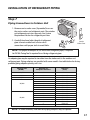
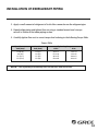
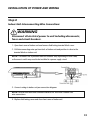
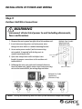
Piping Height Requirements
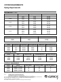
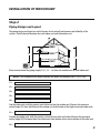
The system piping layout must take in the constraints of vertical height on system performance. The
outdoor unit has a vertical height limit in which it can properly circulate refrigerant in the system.
H2
H1
L2
L3
...Ln
The maximum elevation (H2) between those
two indoor units from bottom of one unit to
bottom of the other unit must be less than:
The maximum elevation (H1) from the bottom
of the outdoor unit to the bottom of the highest
mounted indoor units must be less than:
Maximum Elevation between
Outdoor to Indoor Unit (H1)
Maximum Elevation between
Indoor Units (H2)
Capacity Size
(BtuH)
Distance
ft (m)
Capacity Size
(BtuH)
Distance
ft (m)
18,000
24,000
30,000
36,000
42,000
33 (10)
66 (20)
66 (20)
82 (25)
82 (25)
18,000
24,000
30,000
36,000
42,000
16 (5)
33 (10)
33 (10)
50 (15)
50 (15)
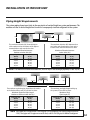
NOTE: If an indoor unit is below the outdoor unit, install oil traps in the suction/gas pipe every 20 vert. ft (6 m)
L =L1
+
L2
+
+
...Ln
LS
The maximum equivalent pipe length from the outdoor
to the farthest indoor units (LS) must be less than:
Maximum Equivalent Pipe Length
Outdoor to Farthest Indoor Unit (Ls)
The maximum total pipe length making up
the system (LT) must be less than:
Maximum Total
Pipe Length (LT)
Capacity Size
(BtuH)
Distance
ft (m)
Capacity Size
(BtuH)
Distance
ft (m)
18,000
24,000
30,000
36,000
42,000
33 (10)
66 (20)
66 (20)
82 (25)
82 (25)
18,000
24,000
30,000
36,000
42,000
66 (20)
230 (70)
230 (70)
230 (70)
262 (80)
NOTE: The outdoor unit is shipped with a full charge of R-410A refrigerant. The factory charge is based on
25 ft (7.6 m) pipe runs. For pipe runs over this limit, add 0.2 oz/ft (20 g/m) of additional refrigerant.
10