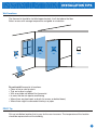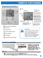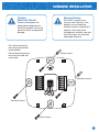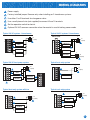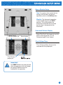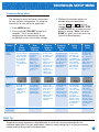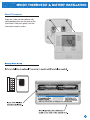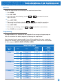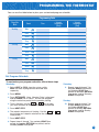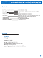
1
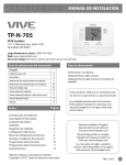
INSTALLATION MANUAL
This manual covers the following models:
• T705
Power Type
Thermostat Applications Guide
D e s c r i p ti o n
Gas or Oil Heat
Yes
Electric Furnace
Yes
Heat Pump (No Aux. or Emergency Heat)
Yes
Heat Pump (with Aux. or Emergency Heat)
No
Multi-stage Systems
No
Heat Only Systems
Yes
Heat Only Systems - Floor or Wall Furnaces
Yes
Cool Only Systems
Yes
Millivolt
Yes
Table of Contents
Installation Tips
Thermostat Quick Reference
Subbase Installation
Wiring
Wiring Diagrams
Technician Setup
Technician Setup Menu
Mounting and Battery Installation
Programming The Thermostat
Programming The Thermostat (cont)
Specifications
Page
2
3
4
5
6
7
8
9
10
11
12
Una versión española de este
manual puede ser descargada
en www.pro1iaq.com
® U.S. Registered Trademark. Patents pending.
Copyright © 2006 Pro1 IAQ, Inc. All rights reserved.
Battery Power
Hardwire (Common Wire)
Hardwire (Common Wire) with Battery Backup
A trained, experienced technician
must install this product.
Carefully read these instructions. You
could damage this product or cause a
hazardous condition if you fail to follow
these instructions.
Need Help?
For assistance with this product please visit
http://www.pro1iaq.com or call Pro1
Customer Care toll-free at 888-Pro1iaq
(776-1427) during normal business hours
(Mon-Fri 9 AM - 6 PM Eastern)
Rev. 0850
1
INSTALLATION TIPS
Wall locations
The thermostat should be installed approximately 4 to 5 feet above the floor.
Select an area with average temperature and good air circulation.
NO
NO
YES
NO
Do not install thermostat in locations:
• Close to hot or cold air ducts
• That are in direct sunlight
• With an outside wall behind the thermostat
• In areas that do not require conditioning
• Where there are dead spots or drafts (in corners or behind doors)
• Where there might be concealed chimneys or pipes
PRO1 Tip
Pick an installation location that is easy for the user to access. The temperature of the location
should be representative of the building.
2
Getting to know your thermostat
1
2
1
LCD
Days of the
week and time
6
Hold is displayed when
thermostat program is
permanently overridden.
Button
options
7
3
4
8
5
2
Glow in the Dark Light Button
3
Fan Switch
4
System Switch
5
Easy Change Battery Door
6
Setpoint Buttons
7
User Buttons
8
Universal Private Label Badge
Displays the user
selectable setpoint
temperature.
Indicates the current
room temperature.
Programmable Time
Period Icons: This thermostat
has 4 programmable time
periods per day.
System operation
indicators: The COOL,
HEAT or FAN icon will
display when the COOL,
HEAT or FAN is on.
NOTE: The compressor
delay feature is active if
these icons are flashing.
The compressor will not
turn on until the 5 minute
delay has elapsed.
Low Battery Indicator:
Replace batteries when
indicator is shown.
Important:
The low battery indicator is displayed
when the AA battery power is low. If
the user fails to replace the battery
within 21 days, the thermostat
display will only show the low battery
indicator as a final warning before the
thermostat becomes inoperable.
3
SUBBASE INSTALLATION
Caution:
Electrical Hazard
Mercury Notice:
All of Pro1’s products are
mercury free. However, if the
product you are replacing
contains mercury, dispose of it
properly. Your local waste
management authority can give
you instructions on recycling
and proper disposal.
Failure to disconnect the
power before beginning to
install this product can cause
electrical shock or equipment
damage.
For vertical mount put
one screw top and one
screw bottom.
Vertical mount
For horizontal mount put
one screw left and one
screw right.
UP
C
RH
O
RC
B
G
W
Y
Horizontal mount
Horizontal mount
Vertical mount
4
WIRING
Caution: Electrical Hazard
Warning:
Failure to disconnect the power
before beginning to install this
product can cause electrical
shock or equipment damage.
All components of the control
system and the thermostat
installation must conform to
Class II circuits per the NEC Code.
Wiring
1. If you are replacing a thermostat, make
note of the terminal connections on the
thermostat that is being replaced. In some
cases the wiring connections will not be
color coded. For example, the green wire
may not be connected to the G terminal.
2. Loosen the terminal block screws. Insert
wires then retighten terminal block screws.
3. Place nonflammable insulation into wall
opening to prevent drafts.
Terminal Designations
W Heat relay
Y Compressor relay
G Fan relay
O Heat pump changeover valve
energized in cooling
RH Transformer power for heating
B Heat pump changeover valve energized
in heating
C Common wire from system transformer
RC Transformer power for cooling
PRO1 Tips:
RH & RC terminals
For single transformer systems, leave the jumper
wire in place between RH and RC. Remove jumper
wire for two transformer systems.
C terminal
The C (common wire) terminal does not
have to be connected when the
thermostat is powered by batteries.
Heat pump systems
If wiring to a heat pump, use a small piece of wire
(not supplied) to connect terminals W and Y.
Wire specifications
Use shielded or non-shielded
18 - 22 gauge thermostat wire.
5
WIRING DIAGRAMS
Power supply
Factory-installed jumper. Remove only when installing on 2-transformer systems.
Use either O or B terminals for changeover valve.
Use a small piece of wire (not supplied) to connect W and Y terminals.
Set fan operation switch to electric
Optional 24 VAC common connection when thermostat is used in battery power mode.
Typical 1H/1C system: 1 transformer
Typical 1H/1C system: 2 transformer
C
REMOVE JUMPER
L2
RC
L2
L1 (HOT)
2
RH
RC
1
R
C
COMPRESSOR
RELAY
C
W
G
1
R
Y
6
L1 (HOT)
2
RH
COMPRESSOR
RELAY
Y
C
6
W
FAN RELAY
G
FAN RELAY
C
HEAT RELAY
HEAT RELAY
L2
L1 (HOT)
1
R
Typical 1H/1C heat pump system
Typical heat-only system
C
C
L2
RC
L1 (HOT)
2
RH
Y
4
RC
COMPRESSOR
RELAY
C
6
W
G
FAN RELAY
R
1
L2
2
RH
L1 (HOT)
Y
R
C
COOL CHANGE
OVER VALVE
3
HEAT CHANGE
OVER VALVE
O
W
B
G
1
6
HEAT RELAY
5
Typical heat-only system with fan
Typical cool-only system
C
C
RC
L2
2
RH
L1 (HOT)
Y
C
R
6
1
RC
L1 (HOT)
RH
R
COMPRESSOR
RELAY
Y
C
1
6
W
W
G
L2
2
FAN RELAY
G
FAN RELAY
HEAT RELAY
6
TECHNICIAN SETUP MENU
Gas or Electric Setup
Gas: For systems that control the fan
during a call for heat, put the fan
operation switch to the GAS position.
Electric: The thermostat operation
switch should be put in the ELEC
position. This setting allows the
thermostat to operate the fan when
the fan relay is connected to the
G terminal.
Fahrenheit/Celsius Display
Select F or C
with the jumper pin
Reset button
Select F or C with the jumper pin on the
back of the thermostat. F is for
Fahrenheit and C is for Celsius.
12 or 24 Hour Time
12 or 24 hour (military time) can be
selected with the jumper pin.
12 or 24 hour
jumper pin
Important:
The RESET button must be pressed
after changing any switch or jumper
pin setting. Batteries must be
installed for this operation.
7
TECHNICIAN SETUP MENU
Technician Setup Menu
This thermostat has a technician setup menu
for easy installer configuration. To setup the
thermostat for your particular application:
3. Configure the installer options as
desired using the table below.
Use the
or
keys to
change settings and the NEXT STEP
or PREV STEP key to move from one
option to another. Note: Only press
DONE key when you want to exit the
Technician Setup options.
1. Press MENU button
2. Press and hold TECH SET button for 3
seconds. This 3 second delay is
designed so that homeowners do not
accidentally access the installer settings.
Filter
Change
Reminder
Room
Temperature
Calibration
Minimum
Compressor
On Time
Compressor
Short Cycle
Delay
Cooling
Swing
Heating
Swing
This feature will flash
“FILT” in the display
after the elapsed run
time to remind the
user to change the
filter. A setting of
“off” will disable this
feature.
This feature allows
the installer to
change the
calibration of the
room temperature
display. For
example, if the
thermostat reads 70°
and you would like it
to read 72° then
select +2.
This feature allows
the installer to select
the minimum run
time for the
compressor. For
example: A setting of
4 will force the
compressor to run for
at least 4 minutes
every time the
compressor turns on,
regardless of the
room temperature.
The compressor short
cycle delay protects
the compressor from
“short cycling”. This
feature will not allow
the compressor to be
turned on for 5
minutes after it was
last turned off.
The swing setting,
often called “cycle
rate”, “differential”
or “anticipation” is
adjustable. A smaller
swing setting will
cause more frequent
cycles and a larger
swing setting will
cause fewer cycles.
The swing setting,
often called “cycle
rate”, “differential”
or “anticipation” is
adjustable. A
smaller swing setting
will cause more
frequent cycles and a
larger swing setting
will cause fewer
cycles.
Adjustment
Options
You can adjust the
filter change
reminder from “off”
to 2000 hours of
runtime in 50 hour
increments.
You can adjust the
room temperature
display to read -4°F
to +4°F above or
below the factory
calibrated reading.
You can select the
minimum compressor
run time from “off”,
“3”, “4”, or “5”
minutes. If 3, 4, or 5
is selected, the
compressor will run
for at least the
selected time before
turning off.
Selecting “ON” will
not allow the
compressor to be
turned on for 5
minutes after the last
time the compressor
was on. Select “off”
to remove this delay.
The cooling swing
setting is adjustable
from ±0.4°F to
±2°F. For example:
A swing setting of
0.5°F will turn the
cooling on at
approximately 0.5°F
above the setpoint
and turn the cooling
off at approximately
0.5°F below the
setpoint.
The heating swing
setting is adjustable
from ±0.4°F to
±2°F. For example:
A swing setting of
0.5°F will turn the
heating on at
approximately 0.5°F
below the setpoint
and turn the heating
off at approximately
0.5°F above the
setpoint.
Factory
Default Settings
Off
0 ºF
Off
On
0.5 ºF
0.4 ºF
Feature
Feature
Description
LCD Will Show
PRO1 Tip
Temperature swing, sometimes called differetial or cycle rate, can be customized for this
individual application. For most applications choose a swing setting that is as long as possible
without making the occupants uncomfortable.
8
MOUNT THERMOSTAT & BATTERY INSTALLATION
Mount Thermostat
Align the 4 tabs on the subbase with
corresponding slots on the back of the
thermostat, then push gently until the
thermostat snaps in place.
9
PROGRAMMING THE THERMOSTAT
Set Time
Follow the steps below to set the day of the week and current time:
1. Press MENU
2. Press SET TIME
3. Day of the week will be flashing. Use the
day of the week.
or
key to select the current
4. Press NEXT STEP
5. The current hour is flashing. Use the
or
key to select the current hour.
When using 12-hour time, make sure the correct a.m. or p.m. choice is selected.
6. Press NEXT STEP
7. Minutes are now flashing. Use the
or
key to select current minutes.
8. Press DONE when completed
Programming
All programmable Pro1 thermostats are shipped with an energy saving pre-program.
You can customize this default program by following the steps below.
Your thermostat can be programmed to have all the weekdays the same, a separate
program for Saturday, and a separate program for Sunday. There are four time periods
for each program (WAKE, LEAVE, RETURN, SLEEP).
Factory Default Program
Day of the
Week
Events
Time
Setpoint
Temperature
(Heat)
Weekday
Wake
6 a.m.
70° F (21° C)
75° F (24° C)
Leave
8 a.m.
62° F (17° C)
83° F (28° C)
Return
6 p.m.
70° F (21° C)
75° F (24° C)
Sleep
10 p.m.
62° F (17° C)
78° F (26° C)
Wake
8 a.m.
70° F (21° C)
75° F (24° C)
Leave
10 a.m.
62° F (17° C)
83° F (28° C)
Return
6 p.m.
70° F (21° C)
75° F (24° C)
Sleep
11 p.m.
62° F (17° C)
78° F (26° C)
Wake
8 a.m.
70° F (21° C)
75° F (24° C)
Leave
10 a.m.
62° F (17° C)
83° F (28° C)
Return
6 p.m.
70° F (21° C)
75° F (24° C)
Sleep
11 p.m.
62° F (17° C)
78° F (26° C)
Saturday
Sunday
Setpoint
Temperature
(Cool)
10
PROGRAMMING THE THERMOSTAT
You can use the table below to plan your customized program schedule.
Programming Table
Day of the
Week
Weekday
Events
Time
Setpoint
Temperature
(Heat)
Setpoint
Temperature
(Cool)
Wake
Leave
Return
Sleep
Saturday
Wake
Leave
Return
Sleep
Sunday
Wake
Leave
Return
Sleep
Set Program Schedule
To customize your program schedule, follow these steps
Weekday:
1. Select HEAT or COOL from the system switch.
Note: You have to program heat and cool each
separately.
2. Press MENU
3. Press SET SCHED. Note: Monday-Friday is displayed
and the WAKE icon is shown. You are now programming the wake time period for the weekday setting.
4. Time is flashing. Use the
or
key to make
your time selection for the weekday WAKE time period.
5. Press NEXT STEP
6. The setpoint temperature is flashing. Use the
or
key to make your setpoint selection for the weekday
wake period.
Saturday:
9.
Repeat steps 4 through 7 for
Saturday WAKE time period,
for Saturday LEAVE time
period, for Saturday RETURN
time period, and for Saturday
SLEEP time period.
Sunday:
10. Repeat steps 4 through 7 for
Sunday WAKE time period,
for Sunday LEAVE time
period, for Sunday RETURN
time period, and for Sunday
SLEEP time period.
7. Press NEXT STEP
8. Repeat steps 4 through 7 for weekday LEAVE time
period, for weekday RETURN time period, and for
weekday SLEEP time period.
11
SPECIFICATIONS & CONTACT INFORMATION
Specifications
The display range of temperature
The control range of temperature
Load rating
Display accuracy
Swing (cycle rate or differential)
Power source
Operating ambient
Operating humidity
Dimensions of thermostat
41ºF to 95ºF (5ºC to 35ºC)
44ºF to 90ºF (7ºC to 32ºC)
1 amp per terminal, 1.5 amp maximum all terminals combined
± 1ºF
Heating is adjustable from 0.4ºF to 2.0ºF
Cooling is adjustable from 0.4ºF to 2.0ºF
18 to 30 VAC, NEC Class II, 50/60 Hz for hardwire (common wire)
Battery power from 2 AA Alkaline Energizer batteries
32º to +105º (0º to +41ºC)
90% non-condensing maximum
4.7”W x 4.4”H x 1.1”D
Pro1 IAQ Inc.
1111 S. Glenstone
Suite 2-100
Springfield, MO 65804
Toll-free: 1-888-Pro1iaq (776-1427)
Toll Number (Outside the USA): 330-821-3600
Web: http://www.pro1iaq.com
Hours of Operation: Monday - Friday 9 AM - 6 PM Eastern
12