1
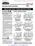
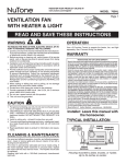
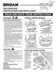
MODEL QTRE100S
Page HUMIDITY SENSING FAN
To register this product visit: www.broan.com
READ AND SAVE THESE INSTRUCTIONS
WARNING
OPERATION
TO REDUCE THE RISK OF FIRE, ELECTRIC SHOCK, OR INJURY TO PERSONS, OBSERVE THE FOLLOWING:
The humidity control and fan can be operated separately. Use a
1- or 2-function wall control. Do not use a dimmer switch to operate
the humidity control. See “Connect Wiring” for details.
1. Use this unit only in the manner intended by the manufacturer.
If you have questions, contact the manufacturer at the address
or telephone number listed in the warranty.
2. Before servicing or cleaning unit, switch power off at service
panel and lock the service disconnecting means to prevent
power from being switched on accidentally. When the service
disconnecting means cannot be locked, securely fasten a prominent warning device, such as a tag, to the service panel.
3. Installation work and electrical wiring must be done by a qualified
person(s) in accordance with all applicable codes and standards, including fire-rated construction codes and standards.
4. Sufficient air is needed for proper combustion and exhausting
of gases through the flue (chimney) of fuel burning equipment to prevent backdrafting. Follow the heating equipment
manufacturer’s guideline and safety standards such as those
published by the National Fire Protection Association (NFPA),
and the American Society for Heating, Refrigeration and Air
Conditioning Engineers (ASHRAE), and the local code authorities.
5. When cutting or drilling into wall or ceiling, do not damage
electrical wiring and other hidden utilities.
6. Ducted fans must always be vented to the outdoors.
7. Acceptable for use over a tub or shower when connected to
a GFCI (Ground Fault Circuit Interrupter) - protected branch
circuit.
8. This unit must be grounded.
CAUTION
1. For general ventilating use only. Do not use to exhaust hazardous or explosive materials and vapors.
2. This product is designed for installation in flat ceilings only. DO
NOT MOUNT THIS PRODUCT IN A WALL.
3. To avoid motor bearing damage and noisy and/or unbalanced
impellers, keep drywall spray, construction dust, etc. off power
unit.
4. Please read specification label on product for further information
and requirements.
SENSOR OPERATION
The humidity-sensing fan uses a sophisticated humidity sensor
that responds to: (a) rapid to moderate increases in humidity or (b)
humidity above a set-point. The humidity sensor may occasionally
turn the fan ON when environmental conditions change.
MANUAL ON WITH TIMED OFF
The humidity sensing fan has an additional operation feature. For
odor or vapor control, the fan can be energized by cycling the
power switch. Once the fan has been energized in this manner, it
will remain on for 20 minutes.
To manually energize the fan:
1.If fan power switch is already ON, proceed to Step 2; otherwise,
turn power switch ON for more than 1 second.
2.Turn fan power switch OFF for less than 1 second.
3.Turn fan power switch back ON and fan will turn ON.
CLEANING & MAINTENANCE
For quiet and efficient operation, long life, and attractive appearance - lower or remove grille and vacuum interior of unit with the
dusting brush attachment.
The motor is permanently lubricated and never needs oiling. If the
motor bearings are making excessive or unusual noises, replace
the motor / blower wheel assembly.
SENSOR CLEANING
The humidity sensor is mounted in the control housing. The sensor
will operate most reliably when cleaned occasionally as follows:
1.Disconnect power at service entrance.
2.Remove the grille. Use a dry dustcloth, clean toothbrush,
or lightly vacuum to clean sensor and grille. DO NOT USE
ABRASIVE CLOTH, STEEL WOOL PADS, OR SCOURING
POWDERS.
3.DO NOT USE cleaning sprays, solvents, or water on or near
the sensor!
Installer: Leave this manual with the homeowner.
MODEL QTRE100S
Page TYPICAL INSTALLATIONS
Housing mounted to
I-joists.
Housing mounted anywhere between
I-joists using hanger bars.
• Locate unit above (GFCI protected circuit required) or
within 5 feet of shower head.
• Locate unit away from heating or cooling sources
which can affect humidity levels.
• Do not locate near window. Unit may respond to the
outdoor humidity level.
• Unit must be installed in ceiling to properly sense
moisture.
• Locate unit only on flat ceilings up to 12 feet high for
proper sensing.
• The fan will operate most efficiently when located
where the shortest possible duct run and minimum
number of elbows will be needed.
• Use a roof cap or wall cap that has a built-in damper
to reduce backdrafts.
2. Plan the wiring.
•
•
Housing mounted to joists.
Housing mounted anywhere between
joists using hanger bars.
Plan to supply the unit with proper line voltage and appropriate power cable. Power cable should be routed to the switch box first and then to the unit (See “CONNECT WIRING” on page 3).
Do not operate this unit with a speed control. Damage to the sensor unit will result.
INSTALL HOUSING &
DUCT
1a.Mount
housing
to joist
or I-joist.
Housing mounted anywhere between trusses using hanger bars.
Housing mounted anywhere between trusses using hanger bars.
PLAN THE INSTALLATION
1. Choose the
installation
location.
The location of
your humidity
sensing fan is
very important.
Use the following guidelines
for best operation:
insulation
(Can be placed
around and over fan
housing.)
ROOF
CAP *
fan
housing
4-in.
ROUND
* Purchase DUCT * 4-in. ROUND
separately
ELBOW(S) *
WALL
CAP *
Use a pliers to
bend housing
TABS
TABS out to
900. Hold housing in place so
that the housing tabs conSPACER
tact the bottom
(use for mounting to I-Joist)
of the joist.
The housing
mounts with
four (4) screws
or nails. Screw
or nail housing
to joist through
lowest holes in
each mounti n g f l a n g e , I-JOIST
then through
highest holes.
NOTE: Mounting to I-JOIST (shown) requires use of
SPACERS (included) between the highest hole of each
mounting flange and the I-joist.
OR
MODEL QTRE100S
Page 1b.Mount housing anywhere between
trusses, joists, or I-joists using hanger
bars.
2. Attach damper/
duct connector.
Snap damper / duct connector onto housing. Make
sure connector is flush
with top of housing and
damper flap falls closed.
Sliding hanger bars are provided to allow for accurate positioning of housing anywhere between framing. They can be
used on all types of framing (I-joist, standard joist, and truss
construction) and span up to 24”.
tab
screws (4)
3. Install
4-inch round ductwork.
Connect 4-inch round
ductwork to damper / duct
connector. Run ductwork
to a roof cap or wall cap.
Tape all ductwork connections to make them
secure and air tight.
mounting
channel (2)
hanger
bar (4)
Attach the MOUNTING CHANNELS to the housing using the
screws supplied. Make sure TABS face “up” as shown.
Use the set of channel mounting holes (marked “STD”) to
mount the housing flush with the bottom of the drywall. Use
the other set of holes (not marked) to mount the housing
flush with the top of the drywall.
CONNECT WIRING
WIRING OPTION #1 - Allows fan to operate in automatic mode or manual mode
(for odor control) by cycling ON/OFF switch.
ON / OFF SWITCH
(PURCHASE SEPARATELY)
ORG
hole for optional screw mounting (4)
ON / OFF
SWITCH
* screw (2)
BLK
BRN
BLK
120
VAC
LINE
IN
WHT
WHT
GRD
GRD
BLK
HUMIDITY
CONTROL
FAN
WHT
WHT
WHT
SWITCH BOX
UNIT
WIRING OPTION #2 - Fan can be turned ON, OFF, or set to operate automatically.
MODEL 68W, 2-FUNCTION CONTROL
(PURCHASE SEPARATELY)
RED
FAN
(ON/OFF)
ORG
COM
nail (4)
bottom edge
of framing
Extend hanger bars to the width of the framing.
Hold ventilator in place with the hanger bar tabs wrapping
around the bottom edge of the framing.
HUMIDITY
CONTROL
(AUTO/OFF)
120
VAC
LINE
IN
Nail ventilator to framing or fasten with screws (not provided)
through holes near nails.
ensure a noise-free mount: Secure hanger bars together
*withTo screws
or use a pliers to crimp mounting channels
tightly around hanger bars.
HUMIDITY
CONTROL
BLK
FAN
WHT
WHT
BRN
BLK
WHT
WHT
GRD
GRD
SWITCH BOX
4. Connect electrical wiring.
BLK
WHT
UNIT
Run 120 VAC house wiring to installation location. Use
proper UL approved connector to secure house wiring to
wiring plate. Connect wires as shown in wiring diagrams.
MODEL QTRE100S
INSTALL GRILLE
SERVICE PARTS
Page 6. Finish ceiling.
Install ceiling material. Cut out around housing.
7. Attach grille to
housing.
Squeeze grille springs
and insert them into slots
on each side of housing.
8. Push grille against
ceiling.
Replacement parts
can be ordered on
our website. Please
visit us at www.
broan.com
WARRANTY
BROAN THREE YEAR LIMITED WARRANTY
Broan warrants to the original consumer purchaser of its products that such products will
be free from defects in materials or workmanship for a period of three years from the date
of original purchase. THERE ARE NO OTHER WARRANTIES, EXPRESS OR IMPLIED,
INCLUDING, BUT NOT LIMITED TO, IMPLIED WARRANTIES OF MERCHANTABILITY
OR FITNESS FOR A PARTICULAR PURPOSE.
During this three-year period, Broan will, at its option, repair or replace, without charge,
any product or part which is found to be defective under normal use and service.
THIS WARRANTY DOES NOT EXTEND TO FLUORESCENT LAMP STARTERS AND
TUBES. This warranty does not cover (a) normal maintenance and service or (b) any
products or parts which have been subject to misuse, negligence, accident, improper
maintenance or repair (other than by Broan), faulty installation or installation contrary
to recommended installation instructions.
The duration of an implied warranty is limited to the three-year period as specified for the
express warranty. Some states do not allow limitation on how long an implied warranty
lasts, so the above limitation may not apply to you.
BROAN’S OBLIGATION TO REPAIR OR REPLACE, AT BROAN’S OPTION, SHALL
BE THE PURCHASER’S SOLE AND EXCLUSIVE REMEDY UNDER THIS WARRANTY. BROAN SHALL NOT BE LIABLE FOR INCIDENTAL, CONSEQUENTIAL OR
SPECIAL DAMAGES ARISING OUT OF OR IN CONNECTION WITH PRODUCT USE
OR PERFORMANCE. Some states do not allow the exclusion or limitation of incidental
or consequential damages, so the above limitation may not apply to you.
This warranty gives you specific legal rights, and you may also have other rights, which
vary from state to state. This warranty supersedes all prior warranties.
To qualify for warranty service, you must (a) notify Broan at the address or telephone
number stated below, (b) give the model number and part identification and (c) describe
the nature of any defect in the product or part. At the time of requesting warranty service,
you must present evidence of the original purchase date.
Broan-NuTone LLC Hartford, Wisconsin www.broan.com 800-558-1711
Key No. Part No.
1
2
3
4
5
6
7
*
8
9
10
11
12
97016466
97016449
98010102
99170245
97017085
97017999
97017478
97017998
97017420
99140199
97018014
QTHB1
99420665
SERVICE NOTE
To remove Blower Assembly:
Unplug motor. Remove
thumbscrew (12) from motor
plate flange. Find the single
tab on the motor plate
(located next to the receptacle).
Push up near motor plate tab
while pushing out on side of
housing. Or insert a straightblade screwdriver into slot in
housing (next to tab) and twist
screwdriver.
Description
Housing
Duct Connector - 4”
Wiring Plate
Screw, #8-18 X .375
Wire Panel/Harness Assembly
Motor/Blower Wheel Assembly
Motor Plate & Control Assembly
Blower Assembly
(includes key nos. 6 & 7)
Grille Assembly
(includes key nos. 8 & 9)
Grille Spring (2 req’d)
Spacer (2 supplied)
Hanger Bar Kit
Thumbscrew, #8-18 x .375
Order service parts by “Part No.” - not by “Key No.”
99044368A