1
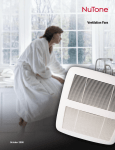
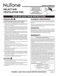
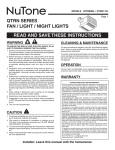
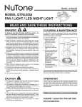
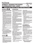
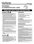
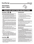
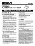
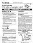
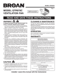
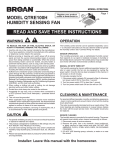
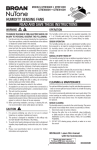
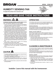
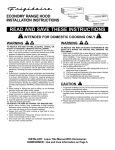
REGISTER YOUR PRODUCT ONLINE AT
www.nutone.com/register
MODEL 765HL
Page VENTILATION FAN
WITH HEATER & LIGHT
READ AND SAVE THESE INSTRUCTIONS
WARNING
OPERATION
TO REDUCE THE RISK OF FIRE, ELECTRIC SHOCK, OR INJURY TO PERSONS, OBSERVE THE FOLLOWING:
1. Use this unit only in the manner intended by the manufacturer.
If you have questions, contact the manufacturer at the address
or telephone number listed in the warranty.
2. Before servicing or cleaning unit, switch power off at service
panel. Lock or tag service panel to prevent power from being
switched on accidentally.
3. Installation work and electrical wiring (including switch location)
must be done by a qualified person(s) in accordance with all
applicable codes and standards.
4. Provide sufficient air for proper combustion and exhausting of
gases through the flue (chimney) of fuel burning equipment
to prevent backdrafting. Follow the combustion equipment
standards such as those published by the National Fire Protection Association (NFPA), the American Society for Heating,
Refrigeration and Air Conditioning Engineers (ASHRAE), and
local codes.
5. When cutting or drilling into wall or ceiling, do not damage
electrical wiring and other hidden utilities.
6. Ducted fans must always be vented to the outdoors.
7. Provide a separate 20 AMP circuit. Use 12 GA., 90o C minimum
power cable which meets code.
8. Do not use a speed control with this product.
9. This unit must be grounded.
Use a 3-Function Control to operate the heater, fan, and light
separately. See “Connect Wiring” for details.
CAUTION
1. For general ventilating use only. Do not use to exhaust hazardous or explosive materials and vapors.
2. This product must be mounted in a flat ceiling only. Installations in ceilings 9-feet high or less will provide
maximum comfort. DO NOT MOUNT THIS PRODUCT IN A
WALL.
3. Install in ceiling only - at least 6 inches from any wall.
4. To avoid motor bearing damage and noisy, unbalanced impellers, keep drywall spray, construction dust, etc. off motor and
impeller.
5. Read specification label on product for information and requirements.
WARRANTY
BROAN-NUTONE ONE YEAR LIMITED WARRANTY
Broan-NuTone warrants to the original consumer purchaser of its products that such products
will be free from defects in materials or workmanship for a period of one year from the date
of original purchase. THERE ARE NO OTHER WARRANTIES, EXPRESS OR IMPLIED,
INCLUDING, BUT NOT LIMITED TO, IMPLIED WARRANTIES OF MERCHANTABILITY
OR FITNESS FOR A PARTICULAR PURPOSE.
During this one-year period, Broan-NuTone will, at its option, repair or replace, without
charge, any product or part which is found to be defective under normal use and service.
THIS WARRANTY DOES NOT EXTEND TO FLUORESCENT LAMP STARTERS AND
TUBES. This warranty does not cover (a) normal maintenance and service or (b) any
products or parts which have been subject to misuse, negligence, accident, improper
maintenance or repair (other than by Broan-NuTone), faulty installation or installation
contrary to recommended installation instructions.
The duration of an implied warranty is limited to the one-year period as specified for the
express warranty. Some states do not allow limitation on how long an implied warranty
lasts, so the above limitation may not apply to you.
BROAN-NUTONE’S OBLIGATION TO REPAIR OR REPLACE, AT BROAN-NUTONE’S
OPTION, SHALL BE THE PURCHASER’S SOLE AND EXCLUSIVE REMEDY UNDER
THIS WARRANTY. BROAN-NUTONE SHALL NOT BE LIABLE FOR INCIDENTAL, CONSEQUENTIAL OR SPECIAL DAMAGES ARISING OUT OF OR IN CONNECTION WITH
PRODUCT USE OR PERFORMANCE. Some states do not allow the exclusion or limitation
of incidental or consequential damages, so the above limitation may not apply to you.
This warranty gives you specific legal rights, and you may also have other rights, which
vary from state to state. This warranty supersedes all prior warranties.
To qualify for warranty service, you must (a) notify Broan-NuTone at the address or telephone
number stated below, (b) give the model number and part identification and (c) describe
the nature of any defect in the product or part. At the time of requesting warranty service,
you must present evidence of the original purchase date.
Broan-NuTone LLC Hartford, Wisconsin www.nutone.com 888-336-3948
Installer: Leave this manual with
the homeowner.
TYPICAL INSTALLATION
CEILING
JOIST, TRUSS,
OR I-JOISTS
CLEANING & MAINTENANCE
For quiet and efficient operation, long life, and attractive appearance - lower or remove grille and vacuum interior of fan with a
dusting brush attachment.
The motor is permanently lubricated and never needs oiling. If
the motor bearings make excessive or unusual noise, replace
the motor with the exact service motor. The impeller should also
be replaced.
Replace light bulb with a 100-Watt (maximum) incandescent
light bulb.
POWER
CABLES
MOUNTING
CHANNELS
HOUSING
CEILING
MATERIAL
GRILLE
Housing mounted to joists, trusses, or I-joists.
Up to 24-inches on-center.
MODEL 765HL
Page PLAN THE INSTALLATION
insulation
(Can be placed
around and over
housing.)
hole for optional screw mounting (4)
* screw (2)
ROOF
CAP *
nail (4)
bottom edge of framing
2. Mount housing.
housing
* Purchase
4-in.
ROUND
DUCT *
separately
4-in. ROUND
ELBOW(S) *
Extend hanger bars to the width of the framing. Hold fan
in place with the hanger bar tabs wrapping around the
bottom edge of the framing.
Nail fan to framing or fasten with screws (not provided)
through holes near nails.
* To ensure a noise-free mount: Secure hanger bars
together with screws or use a pliers to crimp mounting
channels tightly around hanger bars.
WALL
CAP *
The unit will operate most quietly and efficiently when located
where the shortest possible duct run and minimum number of
elbows will be needed.
Use a roof cap or wall cap that has a built-in damper to reduce
backdrafts.
Plan to supply the unit with proper line voltage and appropriate
power cable.
3. Attach
damper
/ duct
connector to
housing.
INSTALLATION
tab
hanger
bars
channel
channel
hanger
bars
1. Insert hanger bars.
Four (4) sliding hanger bars are provided to allow for
accurate positioning of housing anywhere between
framing. They can be used on all types of framing (I-joist,
standard joist, and truss construction) and span up to 24”.
Slide hanger bars into channels on housing. Make sure
hanger bar tabs face “up” as shown.
Snap damper /
duct connector
onto housing.
Make sure
connector is flush
with top of housing
and damper flap
falls closed.
4. Install 4inch round
ductwork.
Connect 4-inch
round ductwork
to damper / duct
connector. Run
ductwork to a roof
cap or wall cap.
Tape all ductwork
connections to
make them secure
and air tight.
MODEL 765HL
Page CONNECT WIRING
INSTALL GRILLE & BULBS
LIGHT
&
FAN
HEAT
BLACK to RED
(Heat)
8. Plug-in
light.
VENTILATOR
HOUSING
RED to BLUE
(Light)
BLACK to BLACK
(Fan)
WHITE to WHITE
WHITE to WHITE
WIRING PLATE
FROM VENTILATOR
GROUND
RED
WHITE
to
WHITE
K
RATING
SPECIFICATIONS
Each two-position rocker
switch is rated 15 A @
120VAC. The total load
on this control must not
exceed 20 A @ 120VAC.
FAN
N
GREE
HEAT
BLACK
BLACK
120 VAC LINE IN
RED
BLU
VENT
SWITCH
BLK
BLK
HEAT
SWITCH
BLK
BLK
RED
WHT
LIGHT
VENT
WHT
WHT
WHT
H E AT
Place grille/
reflector
combination
over protruding
screw and
fasten in place
using acorn nut
provided. HAND
TIGHTEN acorn
nut 1/4 turn after
it is snug.
WHT
WHT
GRD
D O U B L E - G A N G S W I T C H B OX
UNIT
5. Connect electrical wiring.
9. Attach
grille.
LIGHT
SWITCH
GRD
LIGHT
BLAC
caution
LINE
IN
Hold grille
assembly up near
housing. Connect
light plug from
grille assembly to
receptacle inside
of housing.
Run 120 VAC house wiring to installation location. Use
proper UL approved connectors to secure house wiring to
wiring plate. Connect wires as shown in wiring diagram(s).
10. Install
bulb.
INSTALL GRILLE & BULB
The unit
accepts a
100-Watt
(maximum)
incandescent
bulb.
6. Finish ceiling.
Install ceiling material. Cut out ceiling material closely
around housing.
7. Remove
light lens
from grille.
Insert a small
flat-bladed
screwdriver into
the slot at one
end of the light
lens. Carefully pry
the lens out.
11. Attach
light lens.
Hook the tabs
on one end of
the lens into the
slot in the grille.
Lift other end
of lens up and
snap into place.
SCREW
grille
acorn nut
light
reflector
use
this
hole
bottom view
MODEL 765HL
Page 12. Rotate
heater
grille.
Use a flat-bladed
screwdriver to
rotate the round
heater grille to
provide heat
in the desired
direction.
5
6
6
2
1
7
34
9
SERVICE PARTS
Key No.
1
2
3
4
5
6
7
8
9
10
11
12
13
14
15
16
17
18
19
20
21
22
23
24
25
26
27
28
29
30
31
32
33
34
**
**
Part No.
97017572
97017712
97017711
97016449
98010407
99170245
99150471
97017713
99420666
99150415
97017609
98010405
99020294
99160304
99260428
99260488
98010409
97016565
99080606
99020293
98010089
99080602
99100491
97017606
93260454
99150583
93150459
99250959
99260558
97017663
97017688
97005316
99111414
97017739
97017768
97017769
Description
Housing Assembly Slide Mounting Channel
RH (2 req) Slide Mounting Channel
LH (2 req) Duct Connector Assembly, 4” Electrical Knockout Panel Screw, #8-18 X .375” * (5 req) Screw, Ground #10-32 X .500
PH HWH * (2 req) Wire Panel Assembly Wire Clip Screw, 8B X .25
SL HX SR W * (4 req) Heater Scroll Transition Heater Wheel
Screw, #10-24 X .375” * (2 req) Nut, #6-32 X 5/16 * Twin Whiz
(4 req) Nut, #10-24 * Whiz Hex Flange (4 req) Heater Motor Bracket Heater Element Heater Motor Fan Wheel
Heating Element
Mounting Bracket Fan Motor Isolator Bushing (4 req) Partition Assembly Sheet Metal Nut, #8-18 *
(2 req) Screw, #10-24 X 1.25” * Screw, #8-18 X .500” * (2 req) Washer, Flat, #8 * (4 req) Nut, Hex Lock, #8-32 * (4 req) Grille Assembly Reflector Assembly
Acorn Nut Light Lens
Screw Hardware Bag
Heater Scroll Assembly
(Includes Key Nos. 6,
10 thru 19, 21)
Blower Assembly
(Includes Key Nos. 20, 22, 23, 24, 26, 28, 29)
Order service parts by “Part No.” - not by “Key No.”
* Standard hardware - may be purchased locally.
** Not shown assembled.
3
3
8
6
21
10
4
13
15
17
16
19
2
18
10
11
6
12
14
26
20
22
25
23
24
27
28
29
30
31
32
Replacement parts
can be ordered on our
website. Please visit us
at www.nutone.com
33
99044116B
REGISTRE SU PRODUCTO EN LÍNEA EN
www.nutone.com/register
MODELO 765HL
Página VENTILADOR CON
CALEFACTOR Y LUZ
LEA Y CONSERVE ESTAS INSTRUCCIONES
ADVERTENCIA
FUNCIONAMIENTO
PARA REDUCIR EL RIESGO DE INCENDIOS, DESCARGAS
ELÉCTRICAS O LESIONES PERSONALES, OBSERVE LAS
SIGUIENTES PRECAUCIONES:
Utilice un control de 3 funciones para operar el calefactor, el ventilador y la luz
por separado (vea los detalles en la sección “Conexión eléctrica”).
1. Use la unidad sólo de la manera indicada por el fabricante. Si tiene preguntas,
comuníquese con el fabricante a la dirección o al número telefónico que se
incluye en la garantía.
2. Antes de dar servicio a la unidad o de limpiarla, interrumpa el suministro eléctrico
al panel de servicio. Bloquee el panel de servicio o póngale una etiqueta
de seguridad para evitar que alguien conecte accidentalmente la energía
eléctrica.
3. El trabajo de instalación y cableado eléctrico (incluida la ubicación del interruptor)
debe ser realizado por personal calificado y de conformidad con los códigos y
normas correspondientes.
4. Proporcione suficiente aire para que se lleve a cabo la combustión y extracción
adecuados de los gases a través del tubo de humos (chimenea) del equipo
quemador de combustible, a fin de evitar el contratiro. Siga las normas de los
equipos de combustión tales como las establecidas en los códigos locales y las
publicadas por la Asociación Nacional de Protección contra Incendios (National
Fire Protection Association, NFPA) y la Sociedad Americana de Ingenieros de
Calefacción, Refrigeración y Aire Acondicionado (American Society for Heating,
Refrigeration and Air Conditioning Engineers, ASHRAE).
5. Al cortar o perforar a través de la pared o del techo, tenga cuidado de no dañar
el cableado eléctrico ni otros servicios ocultos.
6. Los ventiladores entubados siempre deben conectarse hacia el exterior.
7. Proporcione un circuito por separado de 20 A. Use un cable alimentador de
calibre 12 y capacidad de 90°C (mínimo) que cumpla con los códigos.
8. No utilice un control de velocidad con este producto.
9. Esta unidad debe conectarse a tierra.
GARANTÍA
PRECAUCIÓN
1. Sólo para usarse como medio de ventilación general. No debe usarse para la
extracción de materiales ni vapores peligrosos o explosivos.
2. Este producto está diseñado para instalarse solamente en techos planos.
El confort óptimo se obtiene en instalaciones en techos de 9 pies (2.7 m) o
menos. NO MONTE ESTE PRODUCTO EN LA PARED.
3. Instálelo únicamente en techos, a distancias mínimas de 6 pulg. (15 cm) de
cualquier pared.
4. Para evitar daños a los cojinetes del motor y los impulsores ruidosos y no
balanceados, mantenga el motor y el motor impulsor al resguardo de rociados
de yeso, polvos de construcción, etc.
5. Lea la información y los requisitos que aparecen en la etiqueta de
especificaciones.
Garantía limitada de un año
Broan-NuTone garantiza al comprador consumidor original de sus productos por un período de un
(1) año desde la fecha original de compra, que tales productos están libres de defectos en material
y mano de obra. NO HAY OTRAS GARANTÍAS, EXPRESAS O IMPLÍCITAS, INCLUYENDO,
ENTRE OTRAS, GARANTÍAS IMPLÍCITAS DE COMERCIALIZACIÓN O ADAPTABLES A UN
PROPÓSITO EN PARTICULAR.
Durante este período de un año, Broan-NuTone reparará o reemplazará a su opción y sin
costo, cualquier producto o parte que se encuentre defectuoso bajo condiciones normales de
uso y servicio. ESTA GARANTÍA NO CUBRE A LOS ARRANCADORES PARA LÁMPARAS
FLUORESCENTES O A LOS TUBOS FLUORESCENTES, FILTROS, CONDUCTOS, TAPAS
DE TECHO, TAPAS DE PARED Y OTROS ACCESORIOS PARA CANALIZACIÓN. Esta
garantía no cubre (a) Mantenimiento y servicios normales, ni (b) Productos o partes sujetos a
mal uso, negligencia, accidente, mantenimiento inadecuado o reparaciones (por otros ajenos a
Broan-NuTone), instalación defectuosa o una instalación contraria a las instrucciones de
instalación recomendadas.
La duración de cualquier garantía implícita está limitada a un periodo de un año según se
especifica en la garantía expresa. Algunos estados no permiten limitación en cuanto a la
duración de una garantía implícita, por lo que la limitación arriba indicada puede que no se
aplique a usted.
LA OBLIGACIÓN DE BROAN-NUTONE DE REPARAR O REEMPLAZAR A SU OPCIÓN,
SERÁ EL ÚNICO Y EXCLUSIVO RECURSO QUE TENDRÁ EL COMPRADOR BAJO ESTA
GARANTÍA. BROAN-NUTONE NO SERÁ RESPONSABLE POR DAÑOS INCIDENTALES,
CONSECUENTES O ESPECIALES QUE RESULTEN A CONSECUENCIA O SEAN
INDEPENDIENTES DEL USO O DESEMPEÑO DEL PRODUCTO. Algunos estados no permiten
la exclusión o limitación de daños incidentales o consecuentes, de modo que la limitación o
exclusión arriba indicada puede que no se aplique a usted. Esta garantía le proporciona derechos
legales específicos, y usted podría tener otros derechos, los cuales varían de un estado a otro.
Esta garantía reemplaza a todas las garantías anteriores.
Para tener derecho al servicio de garantía, usted debe (a) notificar a Broan-NuTone a la dirección
o al número de teléfono indicado abajo, (b) indicar el número de modelo y la identificación de la
parte y (c) describir la naturaleza de cualquier defecto en el producto o parte. Al momento de solicitar
el servicio por la garantía, usted debe presentar un comprobante de la fecha original de compra.
Broan-NuTone LLC Hartford, Wisconsin www.nutone.com 888-336-3948
Aviso al instalador: Deje este
manual con el dueño de la casa.
INSTALACIÓN TÍPICA
CABLES
ALIMENTADORES
VIGA DE TECHO,
TIRANTE O VIGA EN I
LIMPIEZA Y MANTENIMIENTO
Para lograr un funcionamiento silencioso y eficiente, así como también larga vida y
una apariencia atractiva, baje o retire la rejilla y aspire el interior del ventilador con
un accesorio de cepillo para sacudir polvo.
El motor está permanentemente lubricado y no necesitará nunca ponerle aceite.
Si los cojinetes del motor están haciendo ruido excesivo o inusual, reemplace el
motor con el motor de servicio exacto. También debe reemplazar el impulsor.
Cambie la bombilla por una bombilla incandescente de 100 watts (máximo).
RANURAS DE
MONTAJE
CUBIERTA
MATERIAL
DEL TECHO
REJILLA
La cubierta se monta en las vigas, tirantes o vigas en I.
Hasta 24 pulg. (61 cm) de centro a centro.
MODELO 765HL
Página PLANEACIÓN DE LA
INSTALACIÓN
AISLAMIENTO
(puede ponerse
alrededor de, y sobre
la cubierta)
ORIFICIO PARA MONTAJE
OPCIONAL CON TORNILLO (4)
* TORNILLO (2)
TAPA DE
TECHO *
CLAVO (4)
BORDE INFERIOR DE
LA ESTRUCTURA
2. Monte la cubierta.
CUBIERTA
CONDUCTO
REDONDO DE
4 PULG. *
* Se compra por
separado
CODO(S)
REDONDO(S)
DE 4 PULG. *
Abra las barras de suspensión hasta el ancho de la estructura. Sostenga el
ventilador en su sitio envolviendo las lengüetas de las barras de suspensión
alrededor del borde inferior de la estructura.
Clave el ventilador a la estructura o sujételo con tornillos (no incluidos) a
través de los orificios que están cerca de los clavos.
* Para lograr un montaje silencioso: acople y fije las barras de suspensión
con tornillos, o con un alicate doble los canales de montaje bien justos
alrededor de las barras de suspensión.
TAPA DE
PARED *
El ventilador funcionará con más eficiencia y menos ruido si se ubica en un sitio donde
requiera el tramo de conductos más corto posible y un mínimo número de codos.
Instale una tapa de techo o de pared que tenga un regulador de tiro integrado
a fin de reducir los contratiros.
Alimente la unidad con el voltaje de línea y el cable alimentador apropiados.
3. Acople el
conector del
regulador de
tiro/conducto
a la cubierta.
INSTALACIÓN
LENGÜETA
BARRAS DE
SUSPENSIÓN
CANAL
CANAL
BARRAS DE
SUSPENSIÓN
1. Inserte las barras de suspensión.
Se proporcionan cuatro (4) barras de suspensión deslizantes
para facilitar la colocación adecuada de la cubierta en cualquier parte
entre la estructura. Estas barras se adaptan a toda clase de estructuras
(construcciones de vigas “I”, vigas estándar y tirantes) y se extienden a un
máximo de 24 pulg. (61 cm).
Deslice las barras de suspensión en los canales de la cubierta.
Asegúrese de que las lengüetas de las barras de suspensión estén de
cara hacia arriba, tal como se muestra.
Conecte a presión el
conectador del regulador
de tiro/conducto en la
cubierta. Asegúrese de
que el conector esté al
ras con la parte superior
de la cubierta y que la
aleta del regulador
caiga cerrada.
4. Instale el
conducto
redondo de
4 pulg.
Conecte el conducto
redondo de 4 pulg. al
conector del regulador/
conducto. Extienda el
conducto hacia una
tapa de techo o tapa
de pared. Encinte todas
las conexiones de los
conductos para fijarlas
y hacerlas herméticas
al aire.
MODELO 765HL
Página CONEXIÓN ELÉCTRICA
CALOR
LUZ
Y
VENTILADOR
NEGRO con
ROJO (calor)
INSTALE LA REJILLA Y
LAS BOMBILLAS
CUBIERTA DEL
VENTILADOR
8. Conecte
la luz.
ROJO con
AZUL (luz)
NEGRO con
NEGRO (ventilador)
BLANCO con
BLANCO
BLANCO con
BLANCO
PLACA DE CABLEADO
DEL VENTILADOR
TIERRA
ROJO
BLANCO con
BLANCO
LUZ
NEGR
O
VERD
PRECAUCIÓN
VENTILADOR
E
CALOR
NEGRO
9. Fije la
rejilla.
CAPACIDAD
NOMINAL
NEGRO
Cada interruptor oscilante LÍNEA DE ENTRADA
DE 120 VCA
de dos posiciones tiene
una capacidad nominal de
15 A a 120 VCA. La carga total de
este control no puede ser mayor de 20 A a 120 VCA.
INTERRUPTOR
DE LUZ
ROJO
AZUL
INTERRUPTOR
DEL VENTILADOR
NEGRO
NEGRO
INTERRUPTOR
D E LC A L E FAC TO R
NEGRO
LÍNAEA DE
ENTRADA
BLANCO
TIERRA
LUZ
VENTILADOR
BLANCO
BLANCO
BLANCO
ROJO
NEGRO
CALOR
Coloque el conjunto
rejilla/reflector sobre el
tornillo que sobresale,
y fíjelo usando la
tuerca de caperuza
que se proporciona.
APRIETE CON LA
MANO la tuerca de
caperuza ¼ de vuelta
después de que
esté ajustada.
UNIDAD
Extienda el cableado de la casa de 120 VCA al lugar de la instalación.
Utilice conexiones aprobadas por UL para asegurar el cableado de la
casa a la placa de cableado. Conecte los cables tal como se ilustra en los
diagramas de cableado.
10. Instale la
bombilla.
INSTALE LA REJILLA Y
LA BOMBILLA
La unidad acepta
una bombilla
incandescente
de 100 watts
(máximo).
6. Termine el techo.
Instale el material del techo. Corte el material del techo alrededor de la cubierta.
7. Quite la
lente de luz
de la rejilla.
Inserte un pequeño
destornillador plano en
la rejilla en un extremo
de la lente de luz. Haga
palanca con cuidado
para retirar la lente.
REJILLA
TUERCA DE
CAPERUZA
11. Fije la lente
de luz.
Enganche las
lengüetas por un
extremo de la lente
en la ranura de
la rejilla. Levante
el otro extremo de
la lente y fíjela
en su lugar.
REFLECTOR
DE LUZ
UTILICE
ESTE
ORIFICIO
VISTA INFERIOR
BLANCO
5. Conecte los cables eléctricos.
TORNILLO
BLANCO
TIERRA
CAJA DE INTERRUPTOR DOBLE
Sostenga el conjunto
de la rejilla cerca de
la cubierta. Conecte
el enchufe de la luz del
conjunto de la rejilla al
receptáculo dentro de
la cubierta.
MODELO 765HL
Página 12. Gire la
rejilla del
calefactor.
Con un destornillador
plano, gire la rejilla
del calefactor redonda
para proporcionar
calefacción en la
dirección deseada.
5
6
6
2
1
7
PIEZAS DE REPUESTO
Clave No.
Pieza No.
Descripción
1
2
97017572
97017712
3
97017711
4
97016449
5
6
98010407
99170245
7
99150471
Conjunto de la cubierta
Canal de montaje de deslizamiento,
derecha (se requieren 2)
Canal de montaje de deslizamiento,
izquierda (se requieren 2)
Conjunto de conector del conducto,
4 pulg.
Panel eléctrico de agujeros ciegos
Tornillo No. 8-18 x 0.375 pulg. *
(se requieren 5)
Tornillo de tierra No. 10-32 X 0.500 PH
HWH * (se requieren 2)
Conjunto del panel de cableado
Clip de cable
Tornillo, 8B X 0.25 SL HX SR W *
(se requieren 4)
Desplazador del calefactor
Transición
Disco calefactor
Tornillo No. 10-24 x 0.375 pulg. *
(se requieren 2)
Tuerca de reborde No. 6-32 X 5/16 *
tuerca (se requieren 4)
Tuerca de reborde hexagonal con
brida No. 10-24 * (se requieren 4)
Soporte del motor del calefactor
Elemento del calefactor
Motor del calefactor
Disco del ventilador
Soporte de montaje del elemento
de calefacción
Motor del ventilador
Casquillo del aislante (se requieren 4)
Conjunto de división
Tuerca autorroscante No. 8-18 *
(se requieren 2)
Tornillo, No. 10-24 x 1.25 pulg. *
Tornillo No. 8-18 x 0.500 pulg. *
(se requieren 2)
Arandela plana No. 8 * (se requieren 4)
Tuerca hexagonal de seguridad No. 8-32
* (se requieren 4)
Conjunto de la rejilla
Conjunto del reflector
Tuerca ciega
Lente de luz
Bolsa de tornillería
Conjunto del desplazador del calefactor
(incluye claves No. 6, 10 a 19, 21)
Conjunto del ventilador
(incluye claves No. 20, 22, 23,
24, 26, 28, 29)
8
9
10
97017713
99420666
99150415
11
12
13
14
97017609
98010405
99020294
99160304
15
99260428
16
99260488
17
18
19
20
21
98010409
97016565
99080606
99020293
98010089
22
23
24
25
99080602
99100491
97017606
93260454
26
27
99150583
93150459
28
29
99250959
99260558
30
31
32
33
34
**
97017663
97017688
97005316
99111414
97017739
97017768
**
97017769
Al hacer el pedido de una pieza de servicio se debe especificar el
número de la pieza (no el número de la clave).
* Tornillería estándar: se puede comprar en una ferretería de la localidad.
** No se muestra montado.
34
9
3
3
8
6
21
10
4
13
15
17
16
19
2
18
10
11
6
12
14
26
20
22
25
23
24
27
28
29
30
31
32
Se pueden hacer los pedidos
de las piezas de repuesto en
nuestro sitio web. Visítenos
en www.nutone.com.
33
99044116B