1
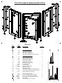
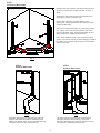
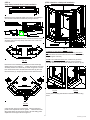
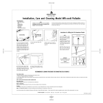
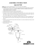
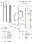
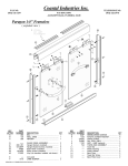
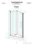
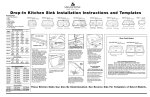
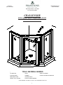
FAX NO.
(314) 231-8165
TELEPHONE NO.
(314) 231-8148
One City Centre - Ste. 2300
St. Louis, Mo 63101
CHALLENGER
MODULAR NEO-ANGLE SHOWER ENCLOSURE
INSTALLATION INSTRUCTIONS
TOOLS / MATERIALS NEEDED
*
1/8" DRILL BIT
LEVEL
SAFETY GLASSES
ELECTRIC DRILL
HAMMER
CLEAR CAULKING OR SEALANT
MEASURING TAPE
CENTER PUNCH
PENCIL / FELT TIP PEN
PHILLIPS SCREW DRIVER
* FOR CERAMIC TILE WALLS, USE A 3/16" MASONRY DRILL BIT
1
EXPLODED VIEW OF MODULAR NEO-ANGLE
(LEFT HAND PIV0T SHOWN)
PARTS LIST
PART
NUMBER
201
B
b1
b2
b3
b4
---210
202
243
834
C
c1
c2
c3
c4
c5
c6
c7
c8
c9
c10
c11
c12
c13
c14
---240
245
241
227
229
226
CP201
CP209
FW 10-093
9842
---6112FHSL
834
C173B
D
E
F
G
H
I
1329
834P
834PFH
638PHPT
C176B
C202B
DESCRIPTION
WALL JAMB
SIDE
SIDE
SIDE
SIDE
SIDE
QUANTITY
2
PANEL ASSEMBLY
PANEL RAILS
PANEL EXPANDER
PANEL CORNER POST
PANEL ASSEMBLY SCREW (not shown)
2
4
2
2
8
DOOR FRAME ASSEMBLY
DOOR FRAME HEADER / SILL
DOOR FRAME PIVOT POST
DOOR FRAME STRIKE POST
DOOR PANEL FRAMES
DOOR PANEL PIVOT STILE
DOOR PANEL STRIKE STILE
PIVOT PIN (not shown)
PIVOT BUSHING
PLASTIC PIVOT WASHER
MAGNETIC STRIPS
(designation not used)
DOOR PANEL ASSEMBLY SCREW (not shown)
DOOR FRAME ASSEMBLY SCREW (not shown)
DOOR GLAZING VINLY (not shown)
1
2
1
1
2
1
1
2
2
2
2
-4
8
PLASTIC SCREW ANCHOR
#8 x 3/4" PAN HEAD PHILLIPS SCREW
#8 x 3/4" FLAT HEAD PHILLIPS SCREW
#6 x 3/8" SELF DRILLING PHILLIPS SCREW
VINYL SWEEP
PANEL GLAZING VINYL (not shown)
6
6
6
6
1
2
Unit Installation Screws (shown full size)
KEY
LETTER
A
SwanStone_07/18/06
STEP 1
Positioning Wall Jambs
Determine the curb centerline, then offset and mark a line
5/8 of an inch toward the outside of shower as shown in
figure 1.
Separate the Wall Jambs (A) from their respective End
Panels (B) as shown in exploded view.
Position Wall Jambs (A) up against shower walls . . .
aligning their outside legs with the offset mark previously
marked on base ledge.
Use a level to plumb Wall Jambs (A). Then using a felt tip
pen, make a mark on the shower walls thru each of the
three (3) installation holes. Remove Wall Jambs (A) and
lightly center punch installation hole locations.
Drill 1" deep installation holes in the locations previously
marked. Use a 3/16" masonry bit when drilling thru ceramic
tile, marble or any masonry type surface and insert Plastic
Screw Anchors (D).
Fig. 1
STEP 2
Installing Wall Jambs
STEP 3
Installing Side Panels
Fig. 2
Fig. 3
Reposition Wall Jambs (A) against shower walls. Realign the Wall Jamb holes with the installation holes
drilled in the shower walls. Secure each Wall Jamb (A)
with three (3) #8 x 3/4" pan head screws (E).
Lift Side Panel (B) onto base ledge and slide Panel
Expander Jamb over Wall Jamb (A). Insure that
Expander Jamb adjustment holes are toward the interior
of the shower. Repeat step for other side.
3
STEP 6 Caulk for a leak proof installation
STEP 4
Vinyl Sweep Insert & Door Frame Installation
Measure the Door Assembly width, then trim the Vinyl Sweep to
3/8” less than measurement obtained (see figure above).
Notch end of Vinyl Sweep as shown. Determine bottom of Door
Assembly and insert Vinyl Sweep into bottom rail. Insert 3/32”
notched end first.
Fig. 5
TO INSURE A LEAK PROOF INSTALLATION:
First: Run a bead of clear mildew resistant caulking around the
outside of shower enclosure where shower unit meets the shower
base (see figures 5 and 5a).
Second: From inside the shower unit, caulk the six (6) circled
areas indicated in figure 5 above (caulk the crevice where the
horizontal member meets the vertical member as shown in fig 5b).
Fig. 4b
Place Door Frame Assembly (C) between the Side Panels (B).
Starting with the pivot side first . . . engage the length of the Panel
Assembly with the Door Assembly as shown in figure 4b. Secure
Door Frame Pivot Post to the Side Panel with three (3) #8 x 3/4"
flat head screws (F). Repeat procedure for the Strike Post side.
Fig. 5a
Fig. 5b
Carefully follow caulking manufacturer's instructions before using
shower.
Fig. 4c
Center shower enclosure on base ledge. Using the Panel Expander Jamb adjustment holes as guides . . . fasten Side Panels
(B) to Wall Jambs (A) using three (3) #6 x 3/8" self drilling panel
adjustment screws (G) as shown in figure 4c.
4
SwanStone_07/18/06