1
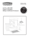
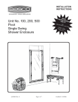
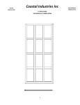
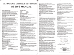
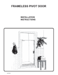
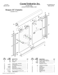
INSTALLATION
INSTRUCTIONS
Unit No. 2850, 3850
Celesta 3/8” Frameless
Sliding Tub/Shower Enclosure
QCI0017 Rev. 2
Page 1 of 8
Certified 09/08/09
MAINTENANCE: Two primary materials are used to manufacture your new Basco enclosure:
tempered glass and anodized aluminum. To assure a long lasting finish on the enclosure, wipe it down
with a towel after each use. Never use a scouring agent to clean the aluminum.
For occasional, more concentrated cleaning efforts, we find that Maintain AquaGlideXP Spray Cleaner
helps minimize water stains and oxidation. Maintain is not only extremely effective at enhancing the
long term performance of glass coated with AquaGlideXP, it can aid in cleaning untreated glass as well.
Ask your distributor about Maintain Spray or visit www.bascoshowerdoor.com/warranty-and-care/careand-cleaning.aspx to purchase online.
Many over the counter cleaners, if applied to aluminum and left on, will harm the metal finish and cause
permanent damage, even though their directions indicate safe use on shower doors. Be sure that any over
spray falling on the aluminum frame is rinsed thoroughly and dried.
INSTALLATION NOTES: Unpack your unit carefully and inspect for freight damage. Lay out and
identify all parts using the instruction sheets as a reference. Before discarding the carton, check to see that
no small hardware parts have fallen to the bottom of the box. If any parts are damaged or missing, refer
to the descriptions noted in the instructions when contacting your dealer for replacements.
Handle the glass panels carefully and protect the edges. Safety tempered glass is very resistant to
breakage, but the sharp corners of the panels can damage tile and floor surfaces.
Please wear safety glasses whenever drilling or cutting. When drilling holes in the ceramic tile or marble,
use a center punch and hammer to carefully break the surface glaze so the drill can start without skidding.
To install your BASCO Shower Door you will need the following: tape measure, level, #2 Phillips
screwdriver, 3/16” wrench, drill, 1/8” and 3/16” drill bits, hacksaw, pencil, and caulking (clear silicone
recommended). Optional tools include a miter box for cutting parts to length, files, center punch, and
masking tape. For drilling tile a 3/16” masonary bit is recommened.
NOTE: Tempered glass cannot be cut.
Although safety tempered glass is very resistant to breakage, the glass can still
break if unequal pressure is placed on it during installation. Use caution. In addition, the sharp corners of the panels can damage tile and floor surfaces, so it is best
to handle the glass panels carefully and protect the edges.
For glass treated with AquaGlide™, read the following instructions:
After each use of your shower, use a small plastic bowl, pitcher or a hand held shower head to spray
the shower doors with clean cold water. Pour or spray the cold water along the top edge of the glass.
The majority of the shower’s soapy residual water will drain off. Use a small hand towel to pat dry
the remaining droplets or use a squeegee to clear the droplets.
Once a month, use a nylon sponge to go over the wet glass, rubbing in a circular motion. You should
feel “sticky” places going back to slick again. Then pour water along the top edge of the glass, as you
do after each shower use.
QCI0017 Rev. 2
Page 2 of 8
Certified 09/08/09
2850/3850 Parts List
A. Wall Jamb (2)
B. Bottom Track (w/ silencer) (1)
C. Plastic Wall Anchor (6)
D. #8 x 1 1/2” Truss Head Screw (6)
E. Clear Jamb Bumper (6)
F. Nylon T-Lock (2)
G. Header (1)
H. Hanger Bracket (4) (pre-attached)
J. Glass Door Panel (2)
K. Glass Hole Sleeve (4)
M. Heavy Glass Roller (4)
N. #8-32 x 3/8” Roller Screw (4)
P. Back Plate (4)
R. Clear Plastic Disc (8)
S. Front Plate
U. Towel Bar (2)
V. Bottom Guide (3)
W. #6 x 3/8” Pan Head Screw (3)
X. Nylon Jamb Cover (2)
Y. Basco Label (1)
F
G
Y
X
N
M
H
M
N
F
E
X
A
J
P
D
K
R
S
U
A
S
D
C
U
K
R
P
V
E
W
B
QCI0017 Rev. 2
Page 3 of 8
Certified 09/08/09
C
SHOWER HEAD LEFT
1
SHOWER HEAD RIGHT
The 2850/3850 Celesta sliding enclosure
is supplied with pocketed wall jambs [A]. The
jambs are notched on both ends to fit over the
bottom track. It is important to determine the proper
orientation of the unit before marking and drilling
the walls. For maximum waterproofing, position
the “open” pocket of the wall jamb to the interior
for the shower head wall. This will force the interior
panel to be on the shower head side. (see illustration)
2
Measure the wall-to-wall opening along the
center of the threshold at the bottom. Cut the bottom
track (w/ vinyl silencer) [B] 1/16” short of that
dimension.
Position the bottom track in the center of the threshold
with the raised edge to the exterior. It may be necessary
to file a radius on the ends of the track and wall jambs
to match the corners of the opening.
EXTERIOR
3
Place one wall jamb over the track and against
the wall. Using a level, plumb the wall jamb and mark the
hole locations on the wall with a pencil. Repeat this step
for the other wall jamb. (Be sure that the curb does not move)
Mark along both inside and outside of the track.
Remove all parts and drill the holes.
Tile, marble or solid surface walls:
Drill 3/16” diameter holes into the walls and insert the
plastic wall anchors [C].
Fiberglass or acrylic units can be done two different ways:
If the walls are not reinforced, drill 3/16” diameter holes
and insert the plastic wall anchors. (Toggle bolts may
be used instead but they are not provided).
If the walls are reinforced, only drill 1/8” diameter holes.
QCI0017 Rev. 2
Page 4 of 8
Certified 09/08/09
4
Before replacing the track, force a slight
downward bow into it. This will ensure that the
track fits tight to the threshold in the middle.
SIL
ICO
NE
Run a bead of silicone on both flat surfaces on the
bottom of the track. Then replace the track onto the
threshold using the pencil marks from step #3 as a
guide. Be sure the raised side is on the exterior.
5
Replace one wall jamb and attach it to the wall with
the #8 x 1 1/2” truss head screws [D]. Check the wall jamb
for plumb and tighten the screws.
Repeat for the other wall jamb.
NOTE: Careful not to overtighten.
Peel the backing from four of the clear jamb bumpers [E]
and attach them inside the pockets of the wall jambs. Place
the bumpers approximately 1” above the bottom screw and
1” below the top screw.
Interior
6
This enclosure is equipped with molded nylon
T-Locks [F] for safety. When properly installed, the header
is locked to the wall jambs and cannot be accidently removed.
Measure the wall-to-wall opening at the top of the wall jambs.
Cut the header 1/16” short of that dimension. Check for fit.
TIP: Use a miter box to ensure a straight cut
Slide one of the T-Locks into one end of the header. Set the
header down onto the wall jamb with the T-Lock fitting into
the space behind the wall jamb. Remove the top truss head
screw. Pull the header and T-Lock down until the truss head
screw can be replaced.
Repeat for the other T-Lock.
QCI0017 Rev. 2
Page 5 of 8
Certified 09/08/09
7
Attach the four black heavy-duty roller bearings [M]
to the door hanger brackets [H] as shown using the #8-32 x 3/8”
hex head screws [N]. The rollers should be approximately in the
center of the slots of the bracket fins.
8
Place one panel [J] on the inside of the shower/tub with the
rollers facing the back wall and the textured side of the panel
facing the outside (if applicable). Set it on a drop cloth or piece
of cardboard to protect the glass and the shower/tub surface.
EXTERIOR
EXTERIOR
From the outside of the shower/tub, grab the other panel with the
rollers (and textured side of glass) facing you and lift the panel.
Lower it into the shower/tub and then lift it into the header. Be
sure the bracket fins and rollers are above the track groove.
Carefully lower the panel until the rollers are seated into the groove.
Slide the panel to one side and step inside the shower/tub and
step inside. Repeat the previous steps for the inside panel.
Check for alignment along the bottom and sides of each panel
and adjust the rollers as necessary.
9
Slide one of the clear plastic discs [R], then
a glass hole sleeve [K] onto the threaded back plate [P].
Push the assembly through the hole in the glass panel
so that the glass hole sleeve is flush with the other side
of the panel. Slide the other clear plastic disc onto the
protruding threaded part of the back plate, and then
slide on the front plate [S]. Repeat this for the second
hole on the panel. While holding the towel bar [U] in
place, and screw the back plates into the towel bar. Use
the provided Allen wrench and the small hole drilled into
the side of the back plate to fully tighten the towel bars.
P
R
S
R
U
K
NOTE: Outer panel has towel bar facing Out.
Inner panel has towel bar facing In.
Refer to the diagram in step #1.
QCI0017 Rev. 2
Page 6 of 8
Certified 09/08/09
10
Place one of the clear bottom guides [V]
in the middle of the tub track as shown. Using
the hole in the back of the bottom guide, drill a
1/8” hole into the inside of the tub track.
Attach the bottom guide with a #6 x 3/8” pan
head screw [W].
OPTION: There are two additional bottom guides
included in the hardware. These can be
installed for additional strength and stability.
Follow the previous instructions to do so.
Exterior
11
Remove the protective backing from the two
squares of tape on the back side of the nylon jamb
covers [X]. Place the jamb covers against the wall jambs
over the notches of the wall jambs at the top, inside of
the header. Press in place.
12
Peel the backing from two of the clear jamb
bumpers [E] and place them against the wall jambs
on the outside of the pockets, one on each wall jamb.
Press them into place approximately in the vertical
center of each wall jamb.
NOTE: The placement of these final two clear
jamb bumpers may vary depending on
any out-of-plumb conditions that may
exist. Adjust accordingly.
EXTERIOR
QCI0017 Rev. 2
Page 7 of 8
Certified 09/08/09
Neatly silicone each end of the tub track
where it fits into the wall jambs as well as the
seam between the wall and the wall jamb and the
curb and threshold on the inside of the shower.
SIL
IC
ON
E
SIL
IC
ON
E
13
NOTE: Silicone on the exterior seam is optional.
NOTE: DO NOT USE the shower until the
silicone is completely cured. Check
the tube of silicone for the manufacturer
recommended cure time.
(typically 24 - 48 hours)
14
Remove the paper backing from the BASCO decal [Y]
and apply to the interior side of the header.
QCI0017 Rev. 2
Page 8 of 8
Certified 09/08/09