1
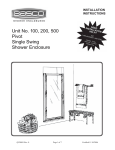
Unit No. 160QNS
Deluxe Pivot
Framed Door Neo Angle
Shower Enclosure
QCI0012 REV. 1
Page 1 of 9
Certified 07/06/05
MAINTENANCE: Two primary materials are used to manufacture your new Basco enclosure:
tempered glass and anodized aluminum. To assure a long lasting finish on the enclosure, wipe it down
with a towel after each use. Never use a scouring agent to clean the aluminum.
For occasional, more concentrated cleaning efforts, we find that Maintain AquaGlideXP Spray Cleaner
helps minimize water stains and oxidation. Maintain is not only extremely effective at enhancing the
long term performance of glass coated with AquaGlideXP, it can aid in cleaning untreated glass as well.
Ask your distributor about Maintain Spray or visit www.bascoshowerdoor.com/warranty-and-care/careand-cleaning.aspx to purchase online.
Many over the counter cleaners, if applied to aluminum and left on, will harm the metal finish and cause
permanent damage, even though their directions indicate safe use on shower doors. Be sure that any over
spray falling on the aluminum frame is rinsed thoroughly and dried.
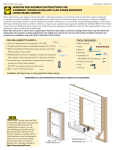
INSTALLATION NOTES: Unpack your unit carefully and inspect for freight damage. Lay out and
identify all parts using the instruction sheets as a reference. Before discarding the carton, check to see that
no small hardware parts have fallen to the bottom of the box. If any parts are damaged or missing, refer
to the descriptions noted in the instructions when contacting your dealer for replacements.
Handle the glass panels carefully and protect the edges. Safety tempered glass is very resistant to
breakage, but the sharp corners of the panels can damage tile and floor surfaces.
Please wear safety glasses whenever drilling or cutting. When drilling holes in the ceramic tile or marble,
use a center punch and hammer to carefully break the surface glaze so the drill can start without skidding.
To install your BASCO Shower Door you will need the following: tape measure, level, #2 Phillips
screwdriver, 3/16” wrench, drill, 1/8” and 3/16” drill bits, hacksaw, pencil, and caulking (clear silicone
recommended). Optional tools include a miter box for cutting parts to length, files, center punch, and
masking tape. For drilling tile a 3/16” masonary bit is recommened.
NOTE: Tempered glass cannot be cut.
Although safety tempered glass is very resistant to breakage, the glass can still
break if unequal pressure is placed on it during installation. Use caution. In
addition, the sharp corners of the panels can damage tile and floor surfaces, so it
is best to handle the glass panels carefully and protect the edges.
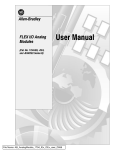
INDENTIFICATION GROOVE
NOTE :
Identification Groove
QCI0012
REV. 1
Each magnetic strip has an indentification groove on the exposed
surface. For proper alignment, the grooves should be opposite
each other (see detail).
Page 2 of 9
Certified
07/06/05
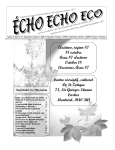
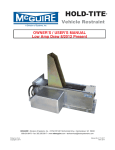
160 Quick-N-Stall
Parts List
K.
L.
M.
N.
P.
R.
S.
T.
V.
A. 3 Curb Sectons
B. 4 135 Anchor Plates
C. 30 #8 x 1/4” Truss Head Screws
D. 3 Header Sections
E. 2 Wall Jambs
F.
6 Plastic Wall Anchors
G. 6 #8 x 1 1/2” Truss Head Screws
H. 2 Pre-Glazed Side Panels
J. 2 135 Posts
2
1
1
1
2
1
2
1
1
Clear Vinyl Jamb Seals
Glazed Door Panel
Pivot Jamb
Strike Jamb (Magnetic)
Snap-in Fillers
Drip Rail
Drip Plugs
Tapered Drip Vinyl
Roll Double Stick Taped
W.
X.
Y.
AA.
BB.
CC.
DD.
EE.
2
1
2
1
1
1
2
1
#10 x 7/16” Sq. Head Set Screws
Nylon Spacer
Nylon Pivot Bushings
Security Washer
Interior Door Handle
Exterior Door Handle
#6 x 1 1/4” Round Head Screws
Basco Decal
D
E
EE
H
D
C
J
D
Y
B
AA
E
K
W
P
C
H
M
F
N
J
G
L
C
DD
F
G
J
BB
CC
R
S
W
T
A
C
Y
P
V
B
C
A
A
X
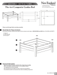
1
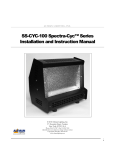
The BASCO 160 Quick-N-Stall Shower
Enclosure is completely reversible and may be installed
pivot-left or pivot-right. For maximum waterproofing, the
pivot jamb should be opposite the shower head. Using the
diagram, determine the correct position for the door in
your particular Quick-N-Stall installation. This
instruction sheet depicts a pivot-right installation.
CAUTION: For safety reasons, the door panel must
always open outward.
PIVOT-RIGHT
PIVOT-LEFT
(HINGE-RIGHT)
(HINGE-LEFT)
2
NOTE: If the curb and header sections come
pre-assembled, skip to Step #3.
Assemble the three curb sections [A] (with weep slots) by
sliding a 135° anchor plate [B] into the mitered ends and
forcing the sections together. The weep slots in the curb
must be to the inside. Screw four #8 x 1/4” truss head
screws [C] through the slots in the anchor plates into the
curbs. As you tighten the screws, be sure the mitered
ends are forced tightly together. To increase the rigidity
of the mitered joint, drill 1/8” holes into the curb through
the round holes in the anchor and install two more #8 x
1/4” screws.
#8 x 1/4”
SCREWS
ANCHOR
PLATE
MITERED
CURB END
MITERED
CURB END
Assemble the three header sections [D] in the same
manner and set the assembly aside.
3
CURB
ASSEMBLY
The curb should sit near the centerline of the sill.
If required, use a file to round the lower ends of the curb
assembly to fit the shower sill properly.
Using a 3/16” drill bit, drill the interior face of the curb
assembly on both ends as shown. These holes may be
predrilled from the factory.
Reposition the curb assembly on the shower sill and mark
its position with a pencil line along the interior and
exterior base.
QCI0012
REV. 1
Page 4 of 9
3/8”
1/4”
3/16” DIA
MEASURE
SHOWER
SILL
IN
TE
RIO
R
Certified
07/06/05
4
Place the two wall jambs [E] into the ends of the
curb assembly [A]. Plumb the jambs and mark the hole
locations on the wall. Masking tape may be used to hold
the curb in place during this operation. Remove all parts
and drill the walls for mounting hardware.
WALL
JAMB
For tile or marble walls, drill six 3/16” diameter holes
and insert the plastic wall anchors [F]. Attachments to
fiberglass or acrylic units can be made in two ways. If
reinforcement is built into the wall of the unit, drill six
1/8” diameter holes to install mounting screws directly
into the reinforcement. If walls are not reinforced, drill
3/16” holes and install plastic wall anchors or Molly bolts
(Molly bolts not supplied by BASCO).
5
Wipe the shower walls and sill, curb assembly
[A] and wall jambs [E] with a clean, dry cloth to remove
any dust or debris. Apply a 1/4” bead of caulk along the
inside of both of the pencil lines marked in Step #3.
Carefully replace the curb assembly in the exact position
marked. Caulk the inside of the curb ends where they
meet the wall. Caulk around the anchor plates [B], screws
[C], and the insides of the mitered joints.
CURB
WEEP SLOT
#8 x 1/2”
SCREW
WALL
JAMB
CAULK
CURB
Replace both wall jambs and attach to the walls with six
#8 x 1 1/2” truss head screws [G].
6
NOTE: Panels with obscure or etched glass
should be installed with the rough surface of the glass to
the exterior of the unit.
WEEP SLOT
TO INTERIOR
PANEL
GLASS
SNAP-IN
VINYL
PANEL RAIL
CURB
Snap one of the side panels [H] into the curb [A] next to
the wall jamb [E]. Slide the panel over into the wall
jamb. Press a 135° post [J] into the curb. Slide the side
panel across until it is centered between the wall jamb
and post. Use masking tape to hold the post in position
temporarily.
PANEL
SIDE RAIL
Repeat for the other side panel and 135° post.
WALL
JAMB
QCI0012
REV. 1
Page 5 of 9
135
POST
PANEL
GLASS
Certified
07/06/05
7
MEASURE AT TOP OF
JAMBS AND POSTS
HEADER
ASSEMBLY
Using a 3/16” drill bit, drill the interior face of the header
assembly on both ends as shown. These holes may be
predrilled from the factory.
3/16”
1/4”
IN
DIA.
3/8”
TE
RIO
R
8
Press the header assembly [D] over the wall
jambs [E], the 135° posts [J] and the pre-glazed panels.
Check the posts for plumb. Adjust as required by varying
the overlap of the header over the wall jambs. You may
need to trim the ends of the header where it meets the
wall. The minimum horizontal dimension for the door
opening is the door panel width (see the graphic in Step
#9) plus 1/2”, maximum is the door panel width plus
1 3/4”.
HEADER
ASSEMBLY
G
OPENIN
Using the holes in the ends of the header and curb as a
guide, drill four 1/8” holes into the wall jambs. Drill 1/8”
holes thru the header and curb into each 135° post as
shown, then enlarge the outer holes with a 3/16” drill for
clearance on the self-tapping screws. Secure the header
and curb to the wall jambs and posts with eight #8 x 1/4”
truss head screws [C].
Press the pivot jamb and strike jamb [N] (with magnetic
strip) over the two 135° posts [J]. Refer to Step #1 for the
proper handling of the door.
NOTE: The magnetic strip on the strike jamb must face
the exterior and the clear vinyl jamb seal on the pivot
jamb must face inward.
QCI0012
REV. 1
Page 6 of 9
135
POST
STRIKE
JAMB
INTERIOR
JAMB
SEAL
PRE-GLAZED
PANEL
PIVOT
JAMB
MAGNETIC
VINYL
PIVOT
JAMB
GLAZED
DOOR
PANEL
WALL
JAMB
1/4”
CURB
ASSEMBLY
9
Strip two clear vinyl jamb seals [K] into the door
panel [L] splash guard and the pivot jamb [M] and trim
flush at both ends. Both vinyls should be turned to trap
water from the shower head. Secure the vinyls with a
small quantity of glue or caulk at each end or by carefully
crimping the vinyl pocket. Set the door panel aside.
1/4”
135
POST
SPLASH
GAURD
DOOR PANEL WIDTH
Certified
JAMB
SEAL
07/06/05
(%!$%2
!33%-",9
6QDSWKHILOOHUV>3@LQWRWKHFXUEDVVHPEO\>$@
DQGKHDGHUDVVHPEO\>'@EHWZHHQWKHGRRUMDPEVZLWK
WKH5$,6('/,3727+((;7(5,25DQGWKHSLYRW
KROHVWRZDUGWKHSLYRWMDPE>0@&HQWHUWKHFXUEILOOHU
LQWKHFXUEEHWZHHQWKHSLYRWDQGVWULNHMDPE>1@XVH
PDVNLQJWDSHWRKROGLQSRVLWLRQ
127( 7KH VQDSLQILOOHUV VKRXOG EH H[DFWO\ ´
ORQJHUWKDQWKHGRRUSDQHOZLGWK
&),,%23
0)6/4
*!-"
(/,%&/2
0)6/4
"53().'
%84%2)/2
3.!0).
&),,%2
#52"
!33%-",9
3XOO WKH ERWWRP HQG RI WKH SLYRW MDPE >0@
WLJKW WR WKH FXUE ILOOHU >3@ DQG SOXPE WKH MDPE 'ULOO
WZR ´ KROHV WKUX WKH SLYRW MDPE DQG LQWR WKH
SRVW>-@LQOLQHZLWKWKHVFUHZVLQWKHKHDGDQGFXUEDQG
DSSUR[LPDWHO\ ´ YHUWLFDOO\ IURP WKH HQGV RI WKH
MDPE'ULOODWKLUGKROHFHQWHUHGEHWZHHQWKHILUVWWZR
$WWDFKWKHSLYRWMDPESHUPDQHQWO\ZLWKWKUHH[´
WUXVVKHDGVFUHZV>&@
6OLGHWKHKHDGHUILOOHU>3@WLJKWDJDLQVWWKHSLYRWMDPE
3XVKWKHVWULNHMDPE>1@WLJKWDJDLQVWWKHILOOHUVWRSDQG
ERWWRP :LWK WKH SLYRW MDPE SOXPE DQG ERWK ILOOHUV
WLJKWEHWZHHQWKHWZRGRRUMDPEVWKHVWULNHMDPEDOVR
ZLOOEHSOXPEDQGSDUDOOHOWRWKHSLYRWMDPE$WWDFKWKH
VWULNH MDPE WR WKH RWKHU SRVW >-@ LQ WKH VDPH
PDQQHUDVWKHSLYRWMDPE
,QVHUWWKHWZR[´VTXDUHKHDGVHW
VFUHZV>:@LQWRWKHWKUHDGHGKROHVLQWKHSLYRWEORFNV
LQWKHWRSDQGERWWRPUDLOVRIWKHJOD]HGGRRUSDQHO>/@
3RVLWLRQWKHSLYRWSLQV´IURPWKHSLYRWVLGHRIWKH
GRRUWKHVLGHRSSRVLWHWKHPDJQHWLFVWULS7LJKWHQWKH
VHWVFUHZVMXVWHQRXJKWRSUHYHQWWKHSLYRWEORFNVIURP
PRYLQJ ILQJHU WLJKW SOXV D TXDUWHU WXUQ $ ´
ZUHQFKQRWVXSSOLHGE\%$6&2ZLOOILWWKHVHWVFUHZ
KHDGV
3UHVVWKHZKLWHQ\ORQVSDFHU>;@RYHUWKHERWWRPSLYRW
SLQRQWKHGRRUSDQHO
v
v
Xv
3#2%73
30,!3('!52$
$//2
0!.%,
0)6/4",/#+
v
3%43#2%7
v
0)6/40).
.9,/.
30!#%2
QCI0012
REV. 1
Page 7 of 9
Certified
07/06/05
13
HEADER
Insert the two nylon pivot bushings [Y] into
the pivot holes in the head and curb fillers [P].
Lift the door panel [L] and insert the top pivot pin into
the pivot bushing in the header filler. Hold the door
vertical and insert the bottom pivot pin into the pivot
bushing in the curb filler. It may be necessary to
remove the header retaining screws and raise the header
slightly to install the door.
DOOR
PANEL
When the door has been set into place, snap the security
washer [AA] over the top pivot pin to hold the upper
pivot bushing in place and prevent accidental
dislodging of the door.
SAFETY
WASHER
NYLON
SPACER
PIVOT
BUSHING
SNAP-IN
FILLER
CURB
TAPE
14
The drip rail [R] is pre-cut from the factory.
Clean the bottom rail and the drip rail thoroughly with
rubbing alcohol to ensure proper adhesion. Unroll the
double stick tape [V] and carefully apply it to the back
of the drip rail (do not peel the tape backing yet).
Insert the tapered drip vinyl [T] into the drip rail.
Position the drip rail flush with the bottom and pivot
side of the door panel [L], then raise the strike side
until the bottom edge of the drip vinyl is parallel to the
curb [A]. Mark the location of each end of the drip rail.
BOTTOM
RAIL
DRIP
RAIL
(ALIGN)
DRIP
VINYL
PIVOT
SIDE
15
Adjust the drip vinyl [T] by sliding it left or
right until it almost touches the curb. Trim the vinyl
(flush with the pivot end and notch 1/4” longer than the
drip rail as shown on the strike end).
11/16”
STRIKE
SIDE
DRIP RAIL
1/4”
TAPERED
DRIP VINYL
DRIP
PLUG
1/16”
The drip plug [S] is supplied with a left and right hand
plug together. Break the right and left drip plug apart
and insert the appropriate plug into the high (strike)
side of the drip rail. Discard the unused drip plug. Peel
off the tape backing and carefully press the drip rail [R]
to the door in the marked position.
NOTE: Cleaners with alcohol content can dissolve
the adhesive that attaches the drip rail. To prevent
this possibility, place a small bead of clear sealant at
the top of the drip rail where it is attached to the
bottom rail.
QCI0012
REV. 1
Page 8 of 9
DRIP
VINYL
BREAK
APART
Certified
07/06/05
16
(2) HANDLE
SCREWS
Attach the interior door handle [BB] and the
exterior door handle [CC] to the door panel [L] with
two #6-32 x 1 1/4” round head screws [DD].
Close the door and check the clearance with the strike
jamb [N]. If necessary, loosen the set screws [W] on
the top and bottom slide bars and adjust the door panel
to align the strike magnets. When the door panel is
properly aligned, tighten the set screws securely.
MAGNETIC
VINYL
IDENTIFICATION
GROOVES
DOOR
PANEL
INTERIOR
HANDLE
INTERIOR
HANDLE
STRIKE
JAMB
EXTERIOR
HANDLE
STRIKE
RAIL
1/8”
EXTERIOR
HANDLE
17
Carefully caulk the interior jamb-to-wall and
curb-to-base joints. Caulk the small gaps at the corners
of the side panels (see arrow on illustration) to prevent
water infiltration. For appearance, you may wish to
caulk the exterior joints as well.
We recommend you wait twenty-four hours before the
first shower to allow the caulking to cure properly.
CA
UL
K
Note: Do not caulk over weep holes
18
Peel off the backing on the BASCO decal
[EE] and apply to the inside surface of the header.
INTERIOR FACE
OF HEADER
DECAL
QCI0012
REV. 1
Page 9 of 9
Certified
07/06/05