1
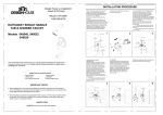
1.Shut off the water supply to the tub and
shower. Verify that the hole sizes and
positions of the holes in the wall are correct:
a. The shower and tub spout outlet holes
should be 1-1/4 in. diameter.
b. The valve access hole should be 6 in.
diameter.
c. The recommended valve depth to the
finished wall is 2 in. min. to 2-1/2 in. max.
Ensure that the valve body (1A) cover is flush
with the finished exterior surface of the wall.
Position the valve body (1A) correctly in the
wall with the "UP" pointing up. The 8 in.
minimum from the valve body to the tub
spout is required for proper operation.
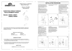
2.Fasten the body assembly (2A) to crass
brace with mounting screws (2B, not
included).
Note: Be sure to position the body (2A)
correctly in the wall, with the markings
"UP" facing upward.
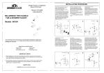
3.TUB & SHOWER OUTLET
CONNECTIONS
Wrap thread sealant tape around the pipe
threads in a clockwise direction, as shown.
Connect the hot and cold water supply lines
(3A, not included), the shower (3B, not
included) and tub outlet pipes (3C, not
included) to the valve body (3D). Connect
the pipe elbows (3E, not included) to the
ends of both pipes, and tighten with a
wrench.
Note: a. The hot water supply lines go into
the H inlet, and the cold water supply lines
go into the C inlet.
b. Do not use PEX or CPVC between
the valve and spout.
1 1/4 in. Diameter
3E
30 in.
Shower Only
3B
48 in.
Tub & Shower
HO
T
6 in. Diameter
3D
CO
3A
48 in.
Shower Only 1A
8 in. Min.
3C
2B
30 in.
Tub & Shower
1 1/4 in.
Diameter
Your new Design House faucet will give you years of trouble free performance. Thank you for
choosing our product for your home. Please read all of these instructions carefully before
installing your new faucet.
Helpful tools to install this faucet:
basin wrench
Teflon tape
(2) crescent wrenches
silicon sealer
flashlight
faucet supply tubes
LD
2A
4.SHOWER ONLY OUTLET
CONNECTIONS
Wrap thread sealant tape around the pipe
threads in a clockwise direction, as
shown. Connect the hot and cold water
supply lines (4A, not included), the
shower outlet pipe (4B, not included) to
valve body (4C). Wrap thread sealant
tape around the threads of the plug (4D),
and insert it into the bottom outlet (4E).
Connect the pipe elbows (4F, not
included) to the end of the pipe, and
tighten with a wrench.
Note: The hot water supply lines go into
the H inlet, and the cold water supply
lines go into the C inlet.
5.FLUSHING
Place the handle (5A) on the valve body
connector (5B) and turn the handle (5A) to
the full on mixed position. Turn on the hot
and cold water supply lines and allow the
water to flow from the outlets for one
minute, or until all foreign matter has been
flushed out. Check for leaks. Shut off the
water at the faucet and supply lines.
Remove the handle (5A).
6.SHOWER FLANGE AND SHOWER ARM
INSTALLATION
Insert the long end of the shower arm (6A)
through the flange (6B), then wrap thread
sealant tape around long end of the shower arm
(6A) in a clockwise direction, as shown. Install
the long end of the shower arm (6A) into the
pipe elbow inside the wall. Tighten the shower
arm (6A), do not over tighten. Wrap thread
sealant tape around the pipe threads of the tub
spout outlet (6C, not included) in a clockwise
direction, as shown. Connect the tub spout
outlet pipe (the tub spout outlet pipe should
project 1-5/16 in. to 3-1/8 in. from the finished
wall) to the lower pipe elbow (6D, not included).
Tighten the elbow and tub spout outlet pipe
connections with a wrench.
6B
IMPORTANT POINTS
4F
When installing your new faucet, hand tighten the connector nuts, then use one wrench to
anchor the fitting and a second wrench to tighten the nut one additional turn. Connections that
are too tight will reduce the integrity of the system.
6A
4B
HO
T
4C
Wrap threaded connections (except aerator thread in spout or where o-ring or rubber sealant
are present) with Teflon tape available from your local hardware or plumbing supply store.
Always wrap in a clockwise direction.
4A
CO
4E
LD
5B
4D
5A
1-5/16 in. to 3-1/8 in.
SAFETY TIPS
Wall
6D
ALWAYS protect your eyes with safety glasses.
6C
7.FOR TUB SPOUT INSTALLATION
Place the spout (7A) onto quick connection
until the spout (7A) becomes flush with the
finished wall and tighten the screw (7B) with
with the Hex wrench (Hex: 3.97mm)
provided.
8.CHECKING FOR LEAKS
Place the handle (8A) on the valve body
connector (8B) and turn the handle to the
full on mixed position. When the valve is
turned on, water normally flows through
the tub spout (8C). To activate the
shower, turn the valve on and pull the
knob (8D) up. Hold the knob (8D) until the
water flows continiously from the shower
arm (8E). Check for leaks. Shut off the
water at the faucet and supply lines.
Remove the handle (8A).
9.ESCUTCHEON AND HANDLE
INSTALLATION
Install the escutcheon (9A) onto the valve
body (9B) using the escutcheon screws
(9C). Place the handle (9D) onto the valve
body (9B) and secure it with the screw (9E).
Use a phillips screwdriver to tighten the
screws. Insert the index (9F) into the handle
(9D).
8E
9A
8B
9B
9C
9D
8A
7A
7B
545921 - Polished Chrome
o
545939 - Polished Chrome
Problem: Faucet leaks from under handle.
Cause: Adjusting ring or cap assembly has loosened.
Action:
1. Move the handle to OFF position. Remove the
index, unscrew the screw and remove the handle.
Unscrew the escutcheon screw and set screw,
then remove the escutcheon and connector.
2. Tighten the adjusting ring by turning it clockwise
with a small screwdriver. Move the ball stem to the
on position and continually tighten the adjusting ring
until the leak stops draining out from around the ball
stem.
3. If the leak does not stop, loosen the adjusting ring
and tighten the entire cap assembly by turning it
clockwise. Re-tighten the adjusting ring as before.
4 . Reinstall the handle.
Mixer ball
Cam
Cap
Adjusting ring
Connector
Disc
Cam packing
Escutcheon
screw
Set screw
9E
8D
8C
o
8C
UP
FOR
SHOWER
9F
Many of these parts come
preassembled. This exploded
diagram is to assist in trouble
shooting.
Escutcheon
Handle
Screw
Index
10.SHOWER HEAD INSTALLATION
Thread the shower head (10A) to the
shower arm (10B).
Your new Design House faucet is designed to give you years of trouble free performance. Avoid abrasive
cleaners, steel wool and harsh chemicals that will dull the finish and void your warranty.
Brass finishes are polished, then protected with a lacquer coating to help prevent tarnishing. Clean these
surfaces only with a damp, soft cloth.
Keep it looking like new by cleaning it periodically with a mild solution of soapy water. Rinse thoroughly and
then dry with a soft cloth.
10B
CONSUMER PROTECTION WARNING
10A
Under the Safe Drinking Water Act, the U.S. Environmental Protection Agency restricts the
amount of lead used in brass and solder. Your new faucet is made in strict compliance with
all government standards. The materials used in the manufacture of this faucet are of industry
standard quality and are similar to other plumbing products having brass fittings.
To reduce the amount of lead in your drinking water, allow the water to run for a moment before
filling your glass and remember to always use cold water for drinking purposes.
Disc spring