1
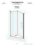
Coastal Industries Inc.
FAX NO.
(904) 641-1697
P.O BOX 16091
JACKSONVILLE, FLORIDA 32245
TELEPHONE NO.
(904) 642-3970
Legend
Inline panel shower enclosure
installation Instructions
(400 Series)
PATENTS PENDING
1
Legend Inline 04-28-2011
EXPLODED VIEW OF MODULAR INLINE PANEL
(RIGHT HAND PIVOT SHOWN)
PARTS LIST
K EY
LE TTE R
A
PART
NUMBER
404
B
b1
b2
b3
b4
---235
404
6112PHS
C 154 B
C
c1
c2
c3
c4
c5
c6
c7
c8
c9
c10
c11
---c13
c14
c15
---440
442
442
227
429
226
C P 201
C P 209
FW 10-093
98-42
5112FHSL
----6112PHS
C 173 B
C 176B
DESCRIPTION
WALL JAMB (door assembly side)
QUANTITY
1
INLINE PANEL ASSEMBLY
Panel Rails
Panel Expander Jamb
Panel Assembly Screws (not shown)
Panel Glazing Vinyl (not shown)
1
2
2
4
---
DOOR FRAME ASSEMBLY
Door Frame Header / Sill
Door Frame Pivot Post (no magnet)
Door Frame Strike Post (with magnet)
Door Panel Rails
Door Panel Pivot Stile
Door Panel Strike Stile
Pivot Pin (not shown)
Pivot Bushing
Plastic Pivot Washer
Magnetic Strips (not shown)
Door Panel Assembly Screw (not shown)
(designation not used)
Door Frame Assembly Screw (not shown)
Door Glazing Vinyl (not shown)
VINYL SWEEP (top and bottom)
1
2
1
1
2
1
1
2
2
2
2
4
--4
--2
1
6
6
12
1
D
E
F
G
H
402
8112
1329
812QPT
447
WALL JAMB (inline panel side)
#8 x 1-1/2" PAN HEAD PHILLIPS SCREW
PLASTIC SCREW ANCHOR
#8 x 1/2" SELF DRILLING QUAD SCREW
HEADER
J
j1
j2
---634FHP
SP116B
CHSL-KIT (Lite)
#6 Flat Head Phillips Screw
Nylon Bushing
2
1
1
1
STEP 1
Position Door Assembly Side Wall Jamb
Determine and mark the curb centerline as shown
in figure 1.
Decide which configuration best suits your needs
door assembly on left / inline panel on right
OR
inline panel on left / door assembly on right
Your choice (of door location above) will determine which wall you will attach the 404 wall jamb
to.
With adjustment holes facing toward the interior
of enclosure, position Wall Jamb (A) up against
the shower wall . . . and center it on the centerline
mark. Use a level to plumb the Wall Jamb. Using
the Wall Jamb's installation holes as guides, drill
three 1" deep installation holes on the wall.
Use a 3/16" masonry bit when drilling through
ceramic tile, marble or any masonry type surface. Insert Plastic Screw Anchors (F). Otherwise use a regular 1/8 drill bit and discard Plastic
Anchors. Secure Wall Jamb with three (3) #8 x
1-1/2" pan head screws (E).
figure 1
STEP 2
Measure Door Assembly width, then position and secure CHSL-KIT on curb base
figure 2
figure 2a
Measure the width of Door Assembly (C) as shown in figure 2, then mark the CHSL-KIT (J) location as shown in figure 2a. Please note that Vinyl
Bushing (j2) IS NOT centered on the centerline, but is located tangent and to the outside of the centerline as shown in figure 2a. Secure Nylon
Bushing (j2) to curb base using the #6 Flat Head Phillips Screw (j1) provided.
3
Legend Inline 04-28-2011
STEP 3
Install Door Assembly
STEP 5
Insert Inline Panel Wall Jamb and Position Inline Panel
figure 3
Detail shows strike on wall side and pivoting at panel,see exploded view on sheet
2 also. Cartwheel the door assembly 180 degrees if you want strike on panel side
and pivoting on wall side.
figure 5
Frame Assembly (C) should be pushed up against Wall Jamb (A).
Lift Door Assembly onto base ledge and over the CHSL-KIT
Assembly (J), then slide the Door Frame (C) into Wall Jamb (A).
Panel Assebly (B) should in turn be pushed up against Frame
Assembly (C).
Whether the door strikes at wall side or pivots at wall side, always
double check to make sure that the door swings out.
Now step inside the shower enclosure and secure the unit to the
remaining shower wall by telescoping the Inline Panel Assembly
side Wall Jamb (D) up against the shower wall as shown. Secure
Wall Jamb (D) with three Installations Screws (E).
Leave door assembly there temporarily and do not fasten at this
time.
Finish securing the Frame and Panel Assemblies. Use three
Adjustment Screws (G) to secure Wall Jamb (A) to Frame Assembly
(C). Next use three Adjustment Screws (G) to secure Panel
Assembly (B) to Frame Assembly (C).
STEP 4
Insert Inline Panel Wall Jamb and Position Inline Panel
STEP 6
Install Header and Caulk outside of Unit.
figure 4
Detail shows strike on wall side / pivoting at panel,see also exploded view on sheet 2
With the installation holes on the same side as the panel's adjustment holes (see figure above), insert the Inline Panel Wall Jamb (D)
into the Inline Panel's Expander Jamb (b2) as shown. Bury the Wall
Jamb into the Panel as far as it will go.
figure 6
Measure opening width at top of unit and trim Header (H) to length
minus 1/16 of an inch. Position Header (H) into place as shown in
figure 6 above and secure utilizing three (3) self drilling screws (G).
Lift Panel Assembly onto base ledge and position the Panel's
Expander Jamb (b2) over the Door Frame's vertical post (c2) . . .
insert Panel Assembly (B) onto Door Assembly (C) as far as it will
go.
TO ENSURE A LEAK PROOF INSTALLATION:
Run a bead of clear mildew resistant caulking around the outside of
shower enclosure where shower unit meets the shower base and
where Wall Jambs meet the wall. Follow caulking manufacturer's
instructions before using shower.
Double check to make sure that the shower assembly is centered
and squared on the base curb.
4