1
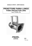
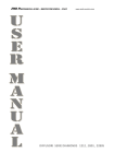
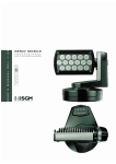
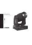
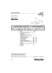
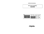
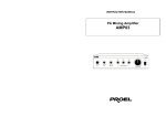
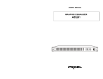
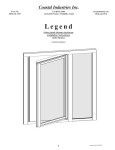
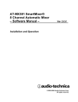
MANUALE UTENTE – USER’S MANUAL
PAR64 MOVING HEAD
PLHT575ML
Rev. 09/2006
INDICE:
DESCRIZIONE……………………………………………………………… p. 3
SPECIFICHE TECNICHE………………………………………………….. p. 3
ISTRUZIONI DI SICUREZZA………………………………………………. p. 3
ACCESSORI COMPRESI NELL’IMBALLO………………………………. p. 4
ISTRUZIONI PER L’INSTALLAZIONE……………………………………. p. 4
INSTALLAZIONE DEL PROIETTORE……………………………………. p. 4
ISTRUZIONI OPERATIVE…………………………………………………. p. 6
CANALI…………………………………………………………………..…… p. 7
APPENDICE 1: ………………………………………..……………………. p. 7
APPENDICE 2: ………………………….………………………………….. p. 8
APPENDICE 3: ……….……………………………………………………… p. 8
APPENDICE 4: ………………………………..…………………………….. p. 10
TABLE OF CONTENTS:
DESCRIPTION……………………………………………………………… p. 11
TECHNICAL SPECIFICATIONS………………………………………….. p. 11
SAFETY INSTRUCTIONS…………………………………………………. p. 11
ACCESSORIES SHIPPED TOGETHER WITH THE MACHINE………. p. 12
INSTALLATION INSTRUCTIONS…………………………………………. p. 12
RIGGING……………………………………………………………………… p. 12
OPERATION INSTRUCTIONS……………………………………………. p. 14
CONTROL CHANNELS…………………………………………………….. p. 15
APPENDIX 1: ………………………………………..………………………. p. 15
APPENDIX 2: ………………………….…………………………………….. p. 16
APPENDIX 3: ……….……………………………………………………….. p. 16
APPENDIX 4: ………………………………..………………………………. p. 18
2
DESCRIZIONE
Grazie per aver scelto il PAR64 a testa mobile Proel BUG TUBE PAR64 Moving
Head.
Per salvaguardare la Vostra sicurezza ed utilizzare l’apparecchio nella maniera più
corretta, leggere attentamente questo manuale ed osservare scrupolosamente le
indicazioni riportate.
Questo apparecchio adotta elevati standard progettuali e costruttivi, è realizzato in
un’elegante scocca realizzata in plastica robusta e resistente alle alte temperature .
E’ presente un led per indicare la connessione alla rete DMX e l’accesso alle varie
funzioni del faro. E’ incorporato anche un circuito elettrico per proteggere dai disturbi
della rete.
Gli angoli di rotazione sono 540° per il Pan e 180° per il Tilt.
SPECIFICHE TECNICHE
-
Tensione di alimentazione: AC 230V / 50Hz (AC 120V / 60Hz USA)
Potenza assorbita:
600W o 800W
Lampada:
PAR64 (HPL 230V 575W/750W
o
575W/750W)
Rigidità dielettrica:
1.5 KV
Resistenza di isolamento: > 2MΩ
Numero di canali:
6
Segnale di controllo:
DMX 512
Controllo:
tramite centralina DMX
Colore effetto:
bianco
Dimmer:
lineare 0-100%
Angoli di scansione:
540° orizzontali (Pan) – 180° verticali (Tilt)
Ingombri (l x a x p):
testa in orizzontale mm. (400 x 420 x 250)
testa in verticale: mm. (400 x 480 x 250)
Peso netto:
kg. 9,5
Altro:
auto check, display digitale
120V
ISTRUZIONI DI SICUREZZA
13 0
A v o i d C u r re n t -P a s s in g
-
H i g h Te m p e r a t u r e L a m p
Interpellare un servizio di assistenza qualificato per effettuare la manutenzione
sull’apparecchio
Assicurarsi che l’apparecchio non sia collegato all’alimentazione prima di
installare la lampada o movimentare lo stesso
3
-
-
Non utilizzare tensione di alimentazione o tipo di lampada diversi da quelli
indicati
Durante l’utilizzo del faro, si potrebbero generare elevate temperature . Non
porre vicino l’apparecchio oggetti infiammabili o esplosivi, non toccare la testa del
faro direttamente con le mani
Assicurarsi che la distanza del faro da tutti gli altri oggetti sia almeno di mt. 1
Non guardare direttamente la lampada, ciò potrebbe provocare danni agli occhi.
ACCESSORI COMPRESI NELL’IMBALLO
-
Proiettore (pz.1)
Cavo XLR (pz.1)
Manuale di istruzioni (pz.1)
Ganci di sicurezza
ISTRUZIONI PER L’INSTALLAZIONE
-
-
-
Questo prodotto è adatto per uso interno, la massima temperatura dell’ambiente
all’interno del quale deve operare deve essere inferiore a 35°C.
Le persone addette all’installazione, al funzionamento ed alla manutenzione del
prodotto, devono avere familiarità con le caratteristiche degli apparecchi per
illuminazione, prima che essi possano intraprendere le varie operazioni
sull’apparecchio stesso. La maggior parte dei danni derivano da azioni non
corrette, derivanti dalla non familiarità con le caratteristiche dei proiettori.
Prima di utilizzare per la prima volta il prodotto, aprire l’imballo per accertarsi che
non ci siano danni provocati durante il trasporto.
Prima di sostituire la lampada, assicurarsi che l’apparecchio sia scollegato dalla
rete e che la lampada si sia raffreddata (la temperatura della stessa può
raggiungere i 200°C).
Aprire il coperchio dell’alloggiamento e sostituire la lampada. Prestare attenzione
a non toccare la superficie della nuova lampada.
Chiudere il coperchio.
Installare l’apparecchio in una zona aerata. Assicurarsi che le ventole funzionino
correttamente e che le griglie di aerazione siano libere.
Il BUG TUBE PAR64 Moving Head, utilizza un fusibile di sicurezza 3A / 250V.
Utilizzare un fusibile dalle stesse caratteristiche.
INSTALLAZIONE DEL PROIETTORE
PERICOLO: durante l’installazione considerare sempre le norme del proprio Stato.
L’installazione deve essere sempre eseguita da personale autorizzato.
L’installazione del proiettore deve essere sempre resa sicura attraverso un ancoraggio
secondario di sicurezza (fune di sicurezza). Questo deve essere fatto in modo che
niente possa cadere nell’eventualità che l’ancoraggio principale venga meno.
Una fune di sicurezza, già sottoposta a tensione a causa di una caduta di un
proiettore, o comunque danneggiata, non deve essere mai riutilizzata
1. sostegni a omega (per collegamento alla truss)
2. gancio di fissaggio alla truss (es. aliscaf - opzionale)
3. vite
4
4. fune di sicurezza
Rimuovere le 4 viti (3) fissate sulla base del PLC64ML. Avvitare ciascun aliscaf con
una vite M12 ai sostegni ad omega. Fissare il primo sostegno ad omega avvitando le
due viti (3) nei rispettivi fori posti al di sotto della base; allo stesso modo fissare il
secondo sostegno.
Usare 2 ganci appropriati per fissare l’apparecchio ad una truss; assicurarsi che il
fissaggio dell’apparecchio sia effettuato correttamente; assicurarsi che la struttura (es.
truss) alla quale viene fissato l’apparecchio sia sicura.
5
ISTRUZIONI OPERATIVE
-
-
-
-
-
Il BUG TUBE PAR64 Moving Head utilizza un display a led per controllare il
settaggio dei canali
Il BUG TUBE PAR64 Moving Head adotta il protocollo internazionale DMX-512
standard. E’ possibile controllare diversi fari tramite una centralina di controllo,
seguendo le indicazioni riguardanti il settaggio dei canali, riportate in appendice
2.
Utilizzare un cavo XLR-XLR, per connettere l’uscita DMX della consolle
all’ingresso DMX del primo proiettore. Connettere l’uscita DMX del primo
proiettore all’ingresso del secondo e così via fino a che tutti gli apparecchi
risultano connessi.
Per installazioni dove il cavo di
segnale deve percorrere lunghe
distanze o dove vi sono disturbi
elettrici, per esempio in discoteca, è
consigliato l’uso di una terminazione
DMX. Il
terminatore
DMX è
semplicemente un connettore XLR
con collegato ad esso una resistenza
da 120Ω (Ohm) tra i piedini 2 e 3. La
resistenza viene innestata nella presa
DIGITAL THRU dell’ultimo proiettore
della catena.
Il BUG TUBE PAR64 Moving Head utilizza una connessione DMX a 3 poli. Se la
centralina di controllo utilizza connettori a 5 poli, sarà necessario un cavo
adattatore 5/3 poli, come indicato nell’appendice 1
All’accensione l’apparecchio effettuerà un reset, dopo il quale sarà operativo.
Non scuotere l’apparecchio quando è in funzione.
6
CANALI
Il BUG TUBE PAR64 Moving Head dispone di 6 canali DMX come segue:
1
2
3
4
5
6
Canale
DIMMER
STROBO
PAN
TILT
PAN fine
TILT fine
Valore DMX
0 - 255
0 - 255
0 - 255
0 - 255
0 - 255
0 - 255
Controllo
0 – 100%
lento - veloce
0 – 540°
0 – 180°
16 Bit
16 Bit
APPENDICE 1: Cavo adattatore XLR 5 poli – 3 poli
3 poli (maschio)
PIN1: GND
PIN2: Segnale +
PIN3: Segnale -
3 poli (femmina)
PIN1: GND
PIN2: Segnale +
PIN3: Segnale -
3 poli (maschio)
PIN1: GND
PIN2: Segnale +
PIN3: Segnale -
5 poli (femmina)
PIN1: GND
PIN2: Segnale +
PIN3: Segnale –
PIN4: ---PIN5: ----
5 poli (maschio)
PIN1: GND
PIN2: Segnale +
PIN3: Segnale –
PIN4: ---PIN5: ----
3 poli (femmina)
PIN1: GND
PIN2: Segnale +
PIN3: Segnale -
7
APPENDICE 2: Settaggio canali DMX
N° faro
Canale DMX start
1
R001
2
R007
3
R013
4
R019
5
R025
6
R031
7
R037
8
R043
9
R049
10
R055
APPENDICE 3: Funzioni
UP
DOWN
M indica il menù, ENTER è utilizzato per confermare tutte le funzioni
Uscita.
8
Display:
ADDR:
Address
indirizzo DMX di partenza di ciascun faro
RSET:
Reset
reset della macchina
PERF:
Velocità di
MAX: velocità 100% - NOMA: velocità 80%
funzionamento
CHSL:
Selezione
canali
ON: 6 canali – OFF: 4 canali
TEST:
Test
auto test per ciascun canale del faro (CH1 – CH6)
TIME:
Time lamp
durata di utilizzo della lampada
DISP:
Display
AOFF: ON display spento – OFF display acceso
NDSP: ON display invertito – OFF display normale
YDIR:
Tilt
direzione positiva (OBVS) o negativa (REVS) del Tilt
XDIR:
Pan
direzione positiva (OBVS) o negativa (REVS) del Pan
Elenco di tutte le funzioni:
Address:
⇒
⇒ ADDR⇒
⇒
Reset:
⇒
⇒ RSET ⇒
⇒
Perf:
⇒
⇒ PERF ⇒
Chsl:
⇒
Test:
Time:
⇒ A001…A512
⇒
⇒ ADDR ⇒
⇒
⇒ MAX – NOMA ⇒
⇒ PERF ⇒
⇒ CHSL ⇒
⇒
⇒ ON – OFF
⇒
⇒ CHSL ⇒
⇒
⇒ TEST ⇒
⇒
⇒ A001…A512
⇒
⇒
⇒ TEST ⇒
⇒
⇒ LAMP ⇒
⇒
⇒
⇒TEST⇒
⇒ TIME
TTME ⇒
⇒
Time:
⇒
TIME
⇒
⇒
⇒
⇒ TEST ⇒
⇒
⇒ AOFF ⇒
⇒ ON – OFF ⇒
⇒ AOFF
⇒
⇒ DISP
⇒
⇒ NDSP ⇒
⇒ ON – OFF ⇒
⇒ NDSP
⇒
⇒ DISP
⇒
⇒
Y dir:
⇒
⇒ TEST ⇒
⇒
⇒ REVS – OBVS ⇒
⇒ YDIR
X dir:
⇒
⇒ TEST ⇒
⇒
⇒ REVS – OBVS ⇒
⇒ XDIR ⇒
9
APPENDICE 4: descrizione dell’apparecchio
SUPPORTO LAMPADA
COPERCHIO
CROMATO
COPERCHIO
ASSE TILT
ASSE PAN
DIMMER
ASSE Y MOTORE
VENTOLA
ENCODER
TRASFORMATORE
SENSORE OTTICO
ASSE X MOTORE
PCB
Nota ogni informazione è soggetta a cambiamenti senza preavviso.
10
DESCRIPTION
Thank you for selecting Proel BUG TUBE PAR64 moving head. In order to ensure
your safty and use the light properly, please read this menu carefully and observe the
rules strickly .
This PAR64 Moving head adopts advanced designing and processing, has an elegant
housing which is made from high intensity and heat resistant complex plastic. There is
a LED to show the DMX code and function option and with a built-in electric circuit to
resist disturbance. The swing angle is 540° (Pan) x 180° (Tilt).
TECHNICAL SPECIFICATION
-
Rated Voltage:
Rated Power:
Lamp:
Dielectric strength:
Insulation resistance:
Number of channels:
Control signal:
Control mode:
Colour effect:
Dimmer:
Scanning angle:
Dimensions (l x h x w):
-
Net weight:
Miscellaneous:
AC 230V / 50Hz (AC 120V / 60Hz USA)
1050W
PAR64 (PLLP64A – PLLPP64B – PLLPP64C)
1.5 KV
> 2MΩ
6
DMX 512
DMX controller
white
linear 0-100%
540° horizontal (Pan) – 180° vertical (Tilt)
head in horizontal position mm. (400 x 420 x 250)
head in vertical position: mm. (400 x 480 x 250)
kg. 9,5
auto check, digital display
SAFETY INSTRUCTIONS
13 0
A v o i d C u r re n t -P a s s in g
-
-
H i g h Te m p e r a t u r e L a m p
Inquiry a qualified maintainer before you maintain the product.
Make sure the light power off before you install the lamp or move the equipment.
Don’t use the different power voltage or different kinds of lamp.
During use this light, it may generate high temperature to cause danger. Please
don’t put any inflammable or explosive material near the equipment, don’t touch
the light directly by hand.
Make sure the distance of the equipment and is over 1 meter
Don’t look at the lamp directly to avoid eyes injury
11
ACCESSORIES SHIPPED TOGETHER WITH THE MACHINE
-
Main body of PAR moving head (1 pc)
XLR cable (1 pc)
User manual (1 pc)
Hook screw and secure screw
INSTALLATION INSTRUCTIONS
-
-
This product is fit to be used indoors, its ambient operating temperature lower
than 35°C.
People assigned to install, operate and maintain the product must familiarize
themselves with the performance of the light fixture before they begin the
operations. Most damages result from incorrect operations arising out of
unfamiliarity with the performance of the product.
Before the product begins to be used for the first time, please open the package
to check if there are any damages caused during transportation
Before replace the lamp, please make sure the power have been cut off, and wait
until the light cool down (the temperature of the lamp can reach 200°C or more).
Open the lamp lid , and replace the lamp . Be care not to touch the surface of the
new lamp.
Close the lid.
Install the light fixture in a place that is well ventilated. Pay attention to checking if
the fan and fan net are smooth.
The BUG TUBE PAR64 moving head uses the 3A/250V safety fuse. Please use
a fuse of the same specification.
RIGGING
DANGER TO LIFE: Please consider the respective national norms during the
installation. The installation must only be carried out by an authorized dealer.
The installation must always be secured with a secondary safety attachment safety
rope). This secondary safety attachment must be constructed in a way that no part of
the installation can fall down if the main attachment fails. A safety rope which already
hold the strain of a crash or which is defective must not be used again.
1. Omega-holders
2. Clamps (optional)
3. Screw
4. Safety-rope
Unscrews 4 screws (3) on the base. Screw one clamp each via a M12 screw and nut
onto the Omega-holders. Insert the quick-lock fasteners of the first Omega-holder into
the respective holes on the bottom of the device. Tighten the quick-lock fasteners fully
clockwise. Install the second Omega-holder.
Use 2 appropriate clamps to rig the fixture on the truss; make sure that the device is
fixed properly; make sure that the structure (truss) to which you are attaching the
fixture is secure.
12
13
OPERATION INSTRUCTIONS
-
-
-
-
-
The BUG TUBE PAR64 moving head uses LED digital display method to control
the channel setting.
The BUG TUBE PAR64 moving head adopts international standard DMX-512
signal, multiple lights can be controlled by the controller due to use the channel
setting (the details are listed in Appendix 2
Use the XLR-XLR cable from the signal output port of the consol to connect the
signal input port of the first light, connect the signal output port of the first light
with the signal input port of the second light, and so on, until all lights are
connected.
For all installation, having long signal
cables or in the presence of electrical
noise, for example a discotheque, it is
recommended practice to use a DMX
terminator: this assist in preventing
corruption of the digital control signal by
external noise. The DMX terminator is
simply an XLR connector with a 120Ω
(Ohm) resistor connected across pins 2
and 3, which is then plugged into the
DIGITAL THRU socket on the last
projector in the chain.
The BUG TUBE PAR64 moving head uses core XLR outlet (plug). A transfer line
from 5 core to 3 core will be needed if the controller you use is 5 core outlet
(plug). (Please refer to Appendix 1).
When power is on, the equipment will undertake self-examination, and can
undertake operation after the self-examination is finished.
Please don’t shake the equipment when it is in operation.
14
CONTROL CHANNELS
The BUG TUBE PAR64 moving head uses international standard DMX512 signal.
There are 6 control channels and the detailed information of control is as follow:
1
2
3
4
5
6
Channel
DIMMER
STROBE
PAN
TILT
PAN fine
TILT fine
DMX value
0 - 255
0 - 255
0 - 255
0 - 255
0 - 255
0 - 255
Control
0 – 100%
slow - fast
0 – 540°
0 – 180°
16 Bit
16 Bit
APPENDIX 1: The transformation between 3 core and 5 core XLR plug
3 pin (male)
PIN1: GND
PIN2: Signal +
PIN3: Signal -
3 pin (female)
PIN1: GND
PIN2: Signal +
PIN3: Signal -
3 pin (male)
PIN1: GND
PIN2: Signal +
PIN3: Signal -
5 pin (female)
PIN1: GND
PIN2: Signal +
PIN3: Signal –
PIN4: ---PIN5: ----
5 pin (male)
PIN1: GND
PIN2: Signal +
PIN3: Signal –
PIN4: ---PIN5: ----
3 pin (female)
PIN1: GND
PIN2: Signal +
PIN3: Signal -
15
APPENDIX 2: DMX-512 channel settings
N° of light
Start DMX channel
1
R001
2
R007
3
R013
4
R019
5
R025
6
R031
7
R037
8
R043
9
R049
10
R055
APPENDIX 3: Function settings
UP
DOWN
M means menù, ENTER i twill be used to confirm every function
Exit
16
Display:
ADDR:
channel)
Address
Set the starting channel number of the light (1 – 512
RSET:
Reset
Set the self check for a lamp body
PERF:
Speed
MAX: speed 100% - NOMA: speed 80%
CHSL:
Channel
selection
ON: 6 channels – OFF: 4 channels
TEST:
Test
Set the self check for each channel (CH1 – CH6)
TIME:
Time lamp
Time of usage the bulb
DISP:
Display
AOFF: ON no display – OFF with display
NDSP: ON reversed display – OFF normal display
YDIR:
Tilt
Set the positive (OBVS) o negative (REVS) Tilt direction
XDIR:
Pan
Set the positive (OBVS) o negative (REVS) Pan direction
List of all the functions:
Address:
⇒
⇒ ADDR⇒
⇒
Reset:
⇒
⇒ RSET ⇒
⇒
Perf:
⇒
⇒ PERF ⇒
Chsl:
⇒
Test:
Time:
⇒ A001…A512
⇒
⇒ ADDR ⇒
⇒
⇒ MAX – NOMA ⇒
⇒ PERF ⇒
⇒ CHSL ⇒
⇒
⇒ ON – OFF
⇒
⇒ CHSL ⇒
⇒
⇒ TEST ⇒
⇒
⇒ A001…A512
⇒
⇒
⇒ TEST ⇒
⇒
⇒ LAMP ⇒
⇒
⇒
⇒TEST⇒
⇒ TIME
TTME ⇒
⇒
Time:
⇒
TIME
⇒
⇒
⇒
⇒ TEST ⇒
⇒
⇒ AOFF ⇒
⇒ ON – OFF ⇒
⇒ AOFF
⇒
⇒ DISP
⇒
⇒ NDSP ⇒
⇒ ON – OFF ⇒
⇒ NDSP
⇒
⇒ DISP
⇒
⇒
Y dir:
⇒
⇒ TEST ⇒
⇒
⇒ REVS – OBVS ⇒
⇒ YDIR
X dir:
⇒
⇒ TEST ⇒
⇒
⇒ REVS – OBVS ⇒
⇒ XDIR ⇒
17
APPENDIX 4: Inner construction
LAMP HOLDER
GLISTEN COVER
LID
Y AXIS BAND
X AXIS BAND
DIMMER
Y AXIS MOTOR
FAN
LEPURN SWITCH
TRASFORMER
OPTO CONTROLLER
X AXIS MOTOR
PCB
Please note: Every information is subject to change without prior notice.
18
PROEL S.p.A.
(World Headquarters – Factory)
Via alla Ruenia 37/43
64027 Sant’Omero (TE) – Italy
Tel. +39 0861 81241
Fax. +39 0861 887862
e-mail: [email protected]
www.proelgroup.com