1
English
Installation of this product at non-recommended measurements may
lead to issues such as water discharge from the showerhead during
tub fill mode.
2.1
3. Installing Your Valve
3.1
English
2. Installation Schematics –
Measuring for Ideal Tub/Shower Performance
3.2
less than 1/4"
(6mm)
E
Tub/Shower
78" (1981mm)
3/4"
(19mm)
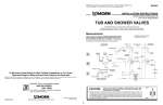
Position the valve body 32 inches from the floor of the
tub basin. The shower arm should be placed 78 inches
above the floor of the tub basin (recommended installation of the shower arm is with a flanged elbow fitting –
not included – and attached to a wood brace). The tub
spout is to be no less than 6 inches and no greater than
11 inches below the valve. If installing a threaded tub
spout, connect to the valve with 1/2 inch pipe or 1/2 inch
copper tubing with a threaded adapter. If installing a slipfit tub spout, connect to the valve with only copper tubing – no threaded adapter is needed.
2-1/4" min.
(57mm)
3-1/2" max.
(89mm)
E
32" (813mm)
Use 1/2" Copper or
IPS Pipe Only
2.2
Shower Only
78” (1981mm)
The center of the valve should be 45 inches to 48 inches
above the shower stall floor. The shower arm should be
placed 78 inches above the floor of the shower stall floor
(recommended installation of the shower arm is with a
flanged elbow fitting – not included – and attached to a
wood brace).
3.3
B
F
O
1
2
Go To Step 4.1
G
Thick Wall Installation
For Walls Thicker Than 1/4 inch
more than 1/4"
(6mm)
4-1/2"
(114mm)
E
E6
3
F
3.4
45-48”
(1143-1219mm)
3.1 The “Thin Wall” method is used when
the tub/shower wall is less than 1/4
inches thick (such as fiberglass tub
surround) and will be the main source
of support for the valve. The plaster
ground (E) remains attached to the
valve. A 2-1/4 inches to 3-1/2 inches
diameter hole is cut thru the wall for this
method.
3.2 Break away the black plastic protective
cover using pliers and rotating clockwise.
3.3 Remove the escutcheon screws (O), place
product identification label (P) on back of
escutcheon, make sure wall is clean, place the
escutcheon (F) over the stop tube (B), then
reinstall the screws (G). A gasket on the back
of the escutcheon provides a seal against the
finished wall.
Ensure cartridge
retainer clip is
installed prior to
escutcheon
installation.
See step 4.3 for tub spout tube length.
6" (152mm) Min.
11" (229mm) Max.
Thin Wall Installation
For Walls Thinner Than 1/4 inch
3.4 The “Thick Wall” installation method is used
when the tub/shower wall is greater than 1/4
inches thick. “Thick Walls” are usually built up with
materials such as cement board, drywall, tile, etc.
The valve is secured by straps (not included) holding the water inlet lines to the framing members
(2X4’s) as shown in steps 2.1 and 2.2. The valve also
features mounting holes to screw the valve to a
cross member attached behind the valve if desired.
Attach the plaster ground (E) to the valve body
using the 2-3/16 inches escutcheon screws (G). Keep
the plaster ground (E) attached to the valve until the
valve has been positioned and secured. The plaster
ground (E) is positioned so that it is flush with the
finished wall. This ensures that the valve will be at
the correct position to accept the trim.
The hole in the wall should be the same size (4-1/2
inches) as the plaster ground (E). This hole will allow
access for future servicing if necessary.
E7