1
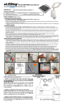
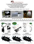
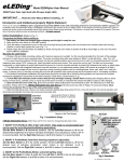
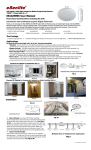
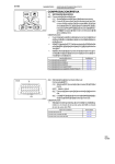
®
Built with
LED Smart Solar Light
IMPORTANT …. Read this User Manual Before Installing...!!!
Included in this package:
Or
1 – eLEDing Solar Light Body 1 – Rechargeable Li-Poly Battery 1 –
1 – Wall Mounting Plate w/hardware
2 – Hardware Package with Screws and Anchors
Initial Installation Set-up (Refer to Fig. 1)
Connecting the Battery before setting up
1. The battery has been pre-charged before shipping and the light is ready for use
2. Make sure the main switch is in the OFF position
3. Open the battery cover on the back of the light and plug the battery into the connector and carefully make sure the plug position is
correct then replace the cover (Fig. 1-1)
4. Initially check the light and battery by moving the switch to AUTO then SMART (ON), it should light up, then turn the switch back to
OFF for installation
Mounting the Light Body
1. The light body must only be mounted in a vertical position and it should be mounted at least 6 to 10 feet above the ground
2. Choose a flat and safe mounting surface. Mark the screw positions through the mounting plate screw holes onto the mounting surface
Use 2 or 4 hole mount, (Fig. 1-2 & 1-3)
3. For wood, vinyl and metal surfaces mount the back plate directly with provided screws. Drill clearance holes using a 3/16" masonry bit
for surface of concrete, brick or stucco. Insert the anchors provided with screws then position the mounting plate and screw the
fasteners in securely
4. Attach the light body unit to the wall mounting plate:
Slide the whole light body onto the wall mount plate from top going down with the light body “hinged” to the mounting plate (Fig. 1-4)
Then secure the mounting with the small securing screw on bottom of the light body (Fig. 1-5)
5. With the light body firmly secured in it’s mounting position, the Pan & Tilt adjustment features can be used to adjust the direction of the
motion detector and the light head directions for optimal performance and coverage. The direction and angle of the motion detector can
be adjusted (Fig. 1-9). The LED light head can also be adjusted horizontally 180o, forward and backward 120o (Fig. 1-10)
Mounting and Connecting the Solar Panel
1. The solar panel must be mounted in a non-obstructed position where it will receive an average of at least 4 hours daily of direct sunlight
all year round. It should be mounted with a tilt of 35°- 80° degrees (Fig 1-6). A sturdy mounting location such as a wall, roof, on top of
patio, under the eaves, secure pole, or floor/ground base. This is required to make sure the solar panel is fasten down properly for all
weather conditions.
2. For Northern hemisphere installations the solar panel should be mounted with a Southerly facing position and visa-versa for Southern
hemisphere installation should face to the North (Australia, South Africa, South America e. g.)
3. Attach the hardware mounting bracket to the solar panel. Determine how far of the 10' connecting wire cord is needed to reach
the position of the light body and then tie the unused cord behind the solar panel with the plastic zip-tie that is provided (Fig. 1-7)
4. Then mark the screw holes through the mounting bracket and secure the solar panel in position with the provided hardware
5. Firmly plug the solar panel plug into the bottom of the light body (Fig. 1-8). The RED-LED indicator (in side the motion ball) will
begin to double flash (Fig. 1-8) indicating that charging status is active during a normal daytime sunny, partially sunny or cloudy day. If
this does not happen please check that the plug is fully plugged into the light body or if there is a problem with the wire.
2 Screws
Connect
the battery
before
using!
1.
4 Screws
3.
3.
2.
5.
4.
P
Pan & Tilt
Pan & Tilt
6.
7.
8.
9
9.
p
10.
A Set-up/Walk test is used to establish the motion sensitivity, Delay Time
and Brightness level settings for the light. After the Set-up/Walk test is
completed the main switch can be set to either the AUTO lighting profile or
the SMART-ON (recommended) lighting profile (test is described on pg. 3)
eLEDing SMART Lighting Profiles & Settings
eLEDing Intelligent microprocessor controlled Solar Light offers two
principal operating profile modes. The Sensitivity/Range of motion,
length of illuminating time, and levels of brightness and dimming are
set and controlled with adjustable dials (Fig. 2)
There are two principal operating profiles for the light. These are
AUTO profile and SMART-ON profile.
The family of eLEDing solar lights use an exclusive Intelligent Power
Management (IPM) embedded feature for managing and optimizing
the Lithium based battery for a full range of operation. This optimizes
the battery’s life cycle to adapt to most environmental conditions
allowing both the battery and light to perform for many years.
Battery will charge in any of the three switch position including OFF.
Fig. 2 Light Profiles & Settings
Rev. EE818WDC 032015 Page 1
eLEDing SMART Light Profiles & Settings
“AUTO” Profile Operation
In AUTO Profile the solar light operates as a motion sensing light and it lights up to full brightness when motion is detected.
The motion Sensitivity/Range can be adjusted by the Right Dial, the delay illuminating time that the light stays on after
activation can be adjusted by the Left Dial (Ref. Fig. 2, page 1).
The illuminating Delay Time can be set using the Left Dial to set the desired length of time for the light to be on after motion is
detected. It is adjustable from 5 to 180 seconds. The light on time will be extended as long as motion is continually detected and
It will not turn off until the motion has stopped and after the illuminating Delay Time has expired. (When set to AUTO profile
the max time of 180 seconds is recommended.)
The motion Sensitivity/Range can be set using the Right Dial to set the desired sensitivity/Range for the application. This
adjustment has a motion sensing range from Low 10’, Med. 35’, High 60’+(For most applications set the dial to between M-H,
in warmer temperature conditions set this slightly higher.)
Cautions: 1) Adjust the Sensitivity/Range so that it is not set too sensitive, this will increase false activations and reduce
stored battery energy. 2) If the IPM feature detects that the battery does not have enough stored energy to operate at full
brightness when AUTO profile is set then it will automatically reduce the light level to half brightness in order to maintain a level
of safe lighting until it again receives enough sunlight in good weather condition to restore it back to normal status.
“SMART-ON” Profile Operation
In SMART-ON profile (switch position set to SMART) the solar light operates as a true Dusk to Dawn light. The unit senses its
surrounding ambient light level and will turn on in darkness providing adjustable moonlight soft glow lighting all night long. When
motion is detected it lights up to it’s maximum brightness or pre-set brightness within the set sensitivity range. In new or if
replacing existing AC light applications SMART-ON is the recommended profile when used as a outdoor and indoor light for
Security and Safety lighting. It can also be used to enhance CCTV applications to illuminate coverage area of the
camera.
The SMART-ON profile has two selectable innovative SMART Modes (A or B) to optimize the way the light brightens up or dims
down after motion has been detected (Ref. Fig. 3).
X
X
X
Fig. 4 Unusual Positions
Fig. 3 A & B Mode
Factory default is Mode A and
preset with maximum brightness
Light Head must only be mounted VERTICALLY only.
Do not mount in any unusual positions as shown in
Fig.4
A) In Mode A maximum brightness is controlled and set by the user. In this mode the dual function Delay-Time dial functions as
a Brightness dial for setting the light level from lowest to maximum brightness (Left Dial). When motion is detected it will
brighten up to the level as pre-set by the Left Dial and when motion stops it will slowly dim down to the lowest factory
fixed pre-set moonlight soft glow lighting.
Caution - The higher the brightness level is set to the more stored battery energy is used when activated by motion. If the IPM
detects that the battery does not have enough capacity to run this mode it will automatically go into AUTO profile (please refer to
AUTO profile description) to provide safety lighting until it receives enough sunlight to operate the feature correctly.
Mode A also allows the brightness level to be adjustable as a portable or table reading/studying light in low level light conditions.
B) In Mode B the minimum soft glow lighting is controlled and set by the user. In this mode the dual function Delay-Time dial
functions as a minimum dial, setting the dimming level of moonlight soft glow lighting. When motion is detected the light will
brighten up to the pre-set factory fixed max level and then dim back down to the level set by the user, Left Dial.
Caution - The higher the minimum soft glow level is set to the more stored battery energy is used to provide soft glow lighting. If
the IPM detects that the battery does not have enough capacity to run this mode it will automatically go into AUTO profile to
provide safety lighting until it receives enough sunlight to operate the feature correctly.
In both Modes A&B If your geographic location has outstanding daytime sunlight conditions all year (California, New Mexico,
Florida of USA e.g.) then you can increase the dimming level or brightness level and take advantage of a brighter projection of
Moonlight soft glow Dusk-to-Dawn lighting. The Sensitivity/Range adjustment functions and setting are identically as
described for the AUTO profile. For most applications the recommending factory preset is Mode A (default, Fig. 3).
In both AUTO and SMART-ON profiles if the IPM detects that the battery does not have enough capacity to run either profile in
critical weather conditions, it will automatically disable illuminating function leaving only the charger active to protect the battery
from over discharge causing damage. Once enough sunlight is received to charge the battery, the unit will go back to AUTO
profile if set in AUTO. If set to SMART-ON profile then it will first go into AUTO profile until it receives enough sunlight energy to
operate SMART-ON profile properly.
Important Note: The A&B Modes only operate in SMART-ON profile. They do not function if it is set with AUTO profile.
Rev. EE818WDC 032015 Page 2
Set Up-Walk Test Procedure and Adjustments
1. To set up eLEDing for your applications the unit comes with a Set-up/Walk Test mode to ensure proper installation and performance is
optimized. To activate this mode move the main switch from OFF to AUTO position. This mode can be reactivated at anytime to adjust your
settings for your application by sliding the switch to OFF then AUTO in any condition day or night.
2. When the main switch is set initially to AUTO from the OFF position for a period of 10 minutes the Set-up/Test mode will be active allowing
the user to adjust the light settings. This mode will work in day or night time conditions. The length of Delay Time for light illumination can be
adjusted at this time for your application from 5 seconds minimum to 180 seconds maximum. During this Set-up/Test mode set this time to 5s
for testing purposes once you are satisfied with your set up then set it to your application (180 seconds is recommended). The Motion
Sensitivity/Range can be adjusted at this time for your application from 10' minimum to 60'+ maximum, also in conjunction adjust the motion
detector head using the Pan and Tilt feature for your application during this time.
3. The Set-up/Walk Test mode is active as long as motion is seen or will automatically disable if 10 minutes has passed without motion being
detected. During this mode, the indicating Red LED light will flash through the motion detection lens providing visual confirmation of motion
detection adjustments. When a period of 10 minutes passes without motion detection the unit will automatically switch to normal operation mode
and will start illuminating once it senses a change to darkness from daylight ambient light conditions.
4. After the initial Set-up/Walk Test is complete the main switch may either be kept in the AUTO profile for Security sensing flood lighting or
moved to the SMART-ON profile for Dusk-to-Dawn security and safety lighting. SMART-ON is the recommended mode providing both
Security and Safety lighting.
Note: The Red LED indicator light inside the ball head flashes for the following reasons: 1) To indicate motion activity during the 10 minutes
initial Set up/Walk Test. 2) To indicate the battery is low when the sensor detects motion during darkness. 3) To indicate charging status during
normal charging either in Sunny, Partly cloudy and cloudy daytime periods, or when the AC/DC-digital charger (option) is being used for
charging in any conditions.
Storage: If this unit has been stored over six months before initial operation then the battery may need to be re-charged. To re-charge the
battery after storage turn the main switch to OFF, connect the battery, plug the wire cord from the solar panel to the light and place it in direct
sunlight for 1-2 days. Or charge for 2-3 hours using only our optional accessory AC-DC Digital/Switched Power Adapter (EE-DPS-0.8A).
User Tips (video reference: youtube.com/watch?v=5eQWsWgFvBA)
Table Light Conversion using optional Table
Stand accessory (EE45/80/18-PBS), Fig. 5). This
option converts the light to a portable table light for
camping, picnics, reading/studying and other indoor or
outdoor activities. Use as a Table Light during low
light level conditions. Move switch to SMART-ON then
make sure to select Mode A (Fig. 3), then adjust Left
Dial (Dimming) for desired reading light level.
An optional AC-DC digital power adapter (EE-DPS0.8A, ) can be used as a quick charger. Also with this
adapter it can be used in either AUTO or SMART-ON
as a standard AC/DC powered motion sensing flood
light with battery back-up capability for indoor/outdoor
security/safety lighting applications. It can be wall or
table mounted, or used as a standard portable/table
light (Fig. 5).
Fig.5 Table Stand & DC Power (option)
Avoid placing objects in front of the motion detector that may affect detecting performance. Avoid installing the unit near air conditioners,
central heaters, or high voltage systems. Avoid placing the motion detector head towards street traffic or other high movement areas which
cause excessive triggers, resulting in shorter battery reserve capacity. If this situation is unavoidable, decrease the sensitivity and delay
time to achieve optimal balance. Motion detector is more sensitive to motions across the device and less sensitive to motion moving
towards or away from it. The solar panel should be mounted where maximum sunlight can be collected. Typically, the solar panel should
face south and avoid facing north (for Northern Hemisphere only, opposite way for Southern Hemisphere) with 35°- 80° tilt up direction
(Refer to Fig. 1-8) It’s fine facing to West or East where sunlight can directly charge the panel for at least 4 hours per day on average.
Use a soft wet cloth to periodically (at least once a one year) clean the solar panel to avoid the reduction of energy output due to
accumulated dust. Clean accumulated snow as soon as possible during the snowing season.
Product Specifications
Note: Installation with factory default settings is recommended for most applications
Optional Accessories:
AC-DC Power Adapter (EE-DPS-0.8A) : Must be switch type (digital) 12VDC/0.5-1.5A with current limited power supply (Fig. 5)
Table Stand (EE45/80/18-PBS) : For use as a table light (Fig. 5). Solar panel 15' extension cable (EE-SPEC-15F).
Important Safety Information
Please unplug the battery when shipping the light or packing for fight traveling. Do not dispose of battery in fire as this may result in an
explosion. Do not expose the light to fire or intense heat as the battery may explode. Do not immerse in water. Never look directly into the light
or shine it into another person’s eyes. Follow proper safety tips to prevent injury such as falling from a ladder during installation. Consult your
local Bi-Laws or local safety guide lines for installing the light fixture on a building.
One Year Limited Warranty
EESGI guarantees this product to be free from defects in material & workmanship for (1) year.
This warranty does not apply to damage from misuse or incorrect installation/ connection. This warranty does not cover accessories, bulbs,
batteries, accidents, alterations, unauthorized use or repair, neglect, misuse, abuse, damages or defects resulting from normal wear and
tear (including chips, fading scratches, abrasions or discoloration due to usage or sun exposure), or failure to follow instructions for care and
maintenance, fire, flood, and Acts of God. This warranty does not include liability for incidental or consequential damages. EESGI is not
responsible for any damages in excess of the retail purchase price of the product under any circumstances. The consumer is responsible for
the installation of, removal of, and reinstallation of the product.
Customer Service: (877)579-3889, www.eesgi.com
Rev. EE818WDC 032015 Page 3
Introduction and Intellectual Property Rights Statement
Thank you for purchasing the eLEDing LED Smart Solar Lights. With its effortless setup and lightweight design the eLEDing LED Smart Light
conforms to all your lighting needs. It was designed and made to provide many years of trouble free service using environmentally friendly SolarHybrid-Lithium based energy technologies. Covered under multiple US, European, China and other international patents granted and pending
worldwide. All rights reserved.
Introduction eLEDing Technology Related Green Systems
EE814WDC
Solar Powered Ultra-Bright
4W CREE LED eMitter
Flood, Spot, Building and
Parking Lot, Security &
Safety Lights, white CCTV
illuminator
Specifications
EE815WDC(WW)/(BP)
Solar Powered Ultra-Bright
5W CREE LED eMitter SelfContained Flood, Spot,
Building Security & Safety
Lights, white CCTV
illuminator
Specifications
eStreet & ePower
EE810-30W/SCLH
EE810-30W/SFLH
EE810-30W/SSLH
EE810W/SPZ
EE810-30W/SRLH
EE840-60W/SPG
Contact Info: (877)579-3889, [email protected], www.eesgi.com
Rev. EE818WDC 032015 Page 4