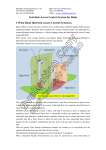
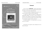
1
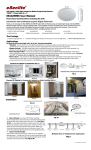
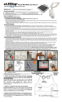
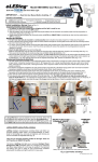
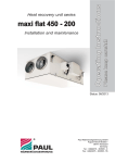
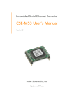
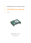
®
Na tu
Model EE860plus User Manual
re W
hite
Il
lumi
natio
n
SMART-plus Solar Light built with 60 super bright LEDs
IMPORTANT …. Read this User Manual Before Installing...!!!
(BP)
(WP)
Introduction and Intellectual property Rights Statement
Thank you for using the EE860plus light is upgraded dual operating SMART modes with outstanding performance and enhanced Li-Battery capacity. With
its effortless setup and lightweight design, the EE860plus LED Smart Light conforms to all your lighting needs. It was designed and built to provide many years of
trouble free service using environmentally friendly Solar-Hybrid-Lithium based energy technology. This product is covered under multiple US, European, China and
other International patents granted and pending worldwide. All rights reserved.
Initial Installation (Refer to Fig. 1)
Connecting the Battery before setting up
1. The battery has been pre-charged before shipping and the light is ready for use
2. Make sure the main switch is in the OFF position
3. Open the battery compartment cover on the back of the light and plug the battery into the connector and carefully make sure the plug
position is correct then replace the cover (Fig. 1-1)
4. Initially check the LED illuminator and battery by slowly moving the main switch to position A or B, it should light up, then turn the switch
back to OFF for installation
Mounting the Light Fixture
1. Choose a flat and stable mounting surface with maximum exposure to sunlight. Cut the mounting template from the back of the package
and use it to mark the two screw mounting holes. The screw mounting holes also have reference “Marks” on the light body. refer. Fig. 1(2)
2. For wood mounting surfaces: Drill the screws into the pre-marked locations and mount the unit on wall. For concrete/brick/stucco: Pre-drill
clearance holes using a 3/16" masonry bit. Insert the plastic anchors and screws. Then mount the unit on wall. This light can be mounted
horizontally in a high position to project light toward the ground or it can be mounted vertically to project light sideways onto walls, or gated areas.
3. This light fixture with integrated solar panel must be mounted in a non-obstructed position where it will receive an average of at least 4
hours daily of direct sunlight all year round. It requires a sturdy mounting location such as a building/house, fence, wall, patio, roof, under the
eaves, or secure pole e.g. Securely mounting this unit and self contained solar panel ensures that it will perform well in all weather conditions.
4. For Northern hemisphere installations this light fixture should be mounted with a Southerly facing position and visa-versa for Southern
hemisphere installation it should face to the North (Australia, South Africa, South America e. g.)
5. A small RED-LED indicator (under motion detector lens) will begin making a double flash indicating that charging status is active
during a normal sunny, partially sunny or cloudy day (If this does not make an indication that means the battery’s status is fully charged).
6. Open the left side cover (refer. Fig. 2) move the function switch to B position (recommended) to start the Initial Set-up or Walk test
procedure. Please refer to the 3 Mode-Selectable One step Set-up instructions and also refer to Page 2 for procedure details. Must
remove the protective film on top of the solar panel before using.
7. After the Initial Set-up test, if there is no motion during the testing delay time period (10 min.), the unit will enter into normal operation and
illuminate automatically only when the environment becomes dark.
Connect
Li-Battery
before
operation
Mounting Mark Points for Setting
Reference as Option on light body
Fig. 1(2)
Drill Screw Holes as per Instructions
Fig. 1 (1)
Mount on the Two Screws
Fig. 1 Installation Steps
3 Mode-Selectable Set-up
(Refer Fig-2 and PG 2 for more info, disregarding light plastic mark)
1. SMART B Profile/Mode (Max-bright adjustable)- This mode is recommended and
can be used for most illumination/lighting applications:
Set the Main Switch to B (downward position). Set the Left Dial between L--H for the
desired Max-brightness level above soft-glow illumination once activated by motion, (M--H
is recommended). Set the Right Dial between L to H (M to below H is recommended)
2. SMART A Profile/Mode (Soft-Glow Dimming brightness adjustable):
Set the Main Switch to A in the center position. Set the Left Dial between L--H for the
desired level of soft-glow illumination when motion is not detected, (L--M is
recommended). Set the Right Dial between L to H (M to below H is recommended)
3. SMART AUTO Profile/Mode (Motion activated lighting only):
Set the Main Switch to either A or B. Set the Left Dial to AUTO in the far left position.
Set the Right Dial between L to H (M to below H is recommended)
Fig. 2 Functions
Rev. EE860plus.072015 Page 1
SMART AUTO Profile
In either A or B position, if the Left Dial is set to Auto (turned all the way to the far left past “L” to the “Auto“ position) then this light will convert
to operate as a traditional motion sensing light. In this SMART AUTO mode it will light up to full brightness when motion is detected. When the
Left Dial is set at the AUTO position the illumination time has a fixed 60 second delay time for the light to be ON after motion is detected and
the lighting will be extended as long as motion is continually detected. It will not turn off until the motion detection has stopped and after the
illuminating Delay Time has expired. The motion Sensitivity/Range can be adjusted using the Right Dial (Ref. Fig. 2, page 1), to set the desired
Sensitivity/Range for the application. This adjustment has a motion sensing range from Low 5’, Med. 15’, High 40’ (For most applications set
the dial to between M--H, in warmer temperature environmental locations set this slightly higher.)
User Tips (video reference: www.eesgi.com)
1. To set up your new eLEDing light for your applications the unit comes with an initial Set-up/Walk Test mode to ensure proper installation and
performance is optimized. To activate this mode move the main switch from OFF to B position as SMART B profile. This test mode can be
reactivated at anytime (night or day) to adjust your settings for your application by sliding the switch to OFF then to B position and
then making your dial settings.
2. When the main switch is set initially to SMART B profile from the OFF position the Set-up/Test mode will be active for a period of 10 minutes
allowing the user to adjust the light settings. This mode will work in day or night time conditions. The Motion Sensitivity/Range (right dial) can be
adjusted at this time for your application from 5' minimum to 45' maximum.
3. The Set-up/Walk Test mode is active as long as motion is detected and it will automatically disable itself if 10 minutes has passed without
motion being detected. During this test period the small Red LED indicator will flash providing visual motion sensing reference as a confirmation
of motion detection adjustments. When a period of 10 minutes passes without motion detection the unit will automatically switch to normal
operation mode. It will stop illumination if the set up test was made during daylight conditions and it will start illumination again once it senses a
change to darkness from daylight ambient light conditions.
4. After the initial Set-up/Walk Test is complete the main switch may either be kept in the SMART B profile or set to the SMART A profile. For
most applications SMART B position is recommended. In both A and B profile if the Intelligent Power Management (IPM) system detects
that the battery does not have enough capacity to operate these modes in critical weather conditions then it will convert to AUTO mode. And if it
detects that there is insufficient battery reserve to operate in Auto mode then it will automatically disable illuminating functions leaving only the
charger active to protect the battery from being damaged. After enough sunlight is received to charge the battery, the unit will first return to
AUTO mode for motion activated lighting until it receives enough sunlight energy to operate the SMART profiles properly.
5. Note: The Red LED indicator light flashes for the following reasons: 1) To indicate motion activity during the 10 minutes initial Set up/Walk
Test. 2) To indicate the battery is low when the sensor detects motion during darkness. 3) To indicate charging status during normal charging
daylight conditions, or when the AC/DC-digital charger (optional) is being used for charging in any conditions.
6. Storage: If this unit has been stored over six months before initial operation then the battery may need to be re-charged. To re-charge the
battery after storage turn the main switch to OFF, connect the battery, plug the wire cord from the solar panel into the light and place it in direct
sunlight for 1-2 days. Or charge for 2-3 hours using only our optional accessory AC-DC Digital/Switched Power Adapter (EE-DPS-0.8A).
The Li-Battery will charge in any of the three switch position including OFF.
7. Spot Light/Projection Lighting as Traditional full bright ON without motion: This option converts the light to provide continuous
adjustable up to full brightness level illumination for up to 8HRS or more. It can be used as a wall washing light to project lighting on signs, flags,
and areas that need spot lighting. Set the main switch to position A. Then make sure to adjust the Left Dial from M or all the way to the max (H)
position as desired, and adjust the Right Dial (Sensitivity) to the lower (L) position (refer Fig 2).
8. An optional AC-DC digital power adapter (EE-DPS-0.8A Fig. 5) can be used as a quick charger. Also with this adapter it can be used in all
profiles and modes as a standard AC/DC powered motion sensing flood light with battery back-up capability for indoor/outdoor security/safety
lighting applications. It can be wall or table mounted, or used as a standard portable/table light (Fig. 5). Using this option it can be used in any
of the three profiles.
9. Important Note: Lowering the Left Dial setting in either A or B profile will extend the battery capacity reserve and provide extended
illuminating ability in geographic locations with poor sunlight, such as North West and North East of American e.g.
Specifications
Li ght f i xt u re: Black Color (BP) or White Color (WP), PC plastic
Detecting Range(adj.): 160°, up to 45’x 45’ (L-5’/1.5m to H-30’/9m)
Light Head: Super 60 SMT LED up to 160º W x 140º V (4000K Color)
Green Energy Storage: 16WH Li-Poly (Lithium based battery)
Solar Panel: 12VDC/3.0W Monocrystalline
Smart Modes: Mode B up to 40+ hrs; Mode A 9-40+hrs w/IPM*
Brightness: Up to 700+ Lumens (=60W standard lamp) on peak
Operation Temp: -4ºF to 125ºF; Consumer Standard Weatherproof (IP54)
Weight: 1.6LBs / Demension: L 13 3/8" x W 4 1/2" x H 3 /3/8"
Complies with: FCC Part 15 Class B and ICES-003:2004. CE
*Continuous dimming illumination/Dusk to Dawn capability claims under fully charged battery and no motion triggered condition.
One Year Limited Warranty
EESGI guarantees this product to be free from defects in material &
workmanship for (1) year.
This warranty does not apply to damage from misuse or incorrect
installation/ connection.
This warranty does not cover accessories, bulbs, batteries, accidents,
alterations, unauthorized use or repair, neglect, misuse, abuse,
damages or defects resulting from normal wear and tear (including
chips, fading scratches, abrasions or discoloration due to usage or sun
exposure), or failure to follow instructions for care and maintenance, fire,
flood, and Acts of God.
This warranty does not include liability for incidental or consequential
damages.
EESGI is not responsible for any damages in excess of the retail
purchase price of the product under any circumstances. The consumer
is responsible for the installation of, removal of, and reinstallation of the
product.
Customer service: (877)579-3889, www.eesgi.com
Bend off this piece for additional
solar panel or AUX power source
Fig. 3 Optional Solar Panel for insufficient sun exposure locations
or indoor use of the light
Rev. EE860plus.072015 Page 2