1
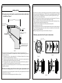
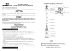
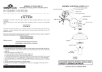
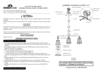
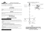
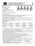
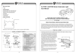
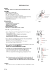
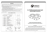
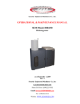
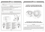
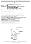
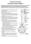
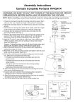
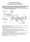
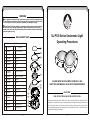
WARNING
! Never operate this Underwater Light for more than 10 seconds unless it is totally submerged
in water. Without total submersion, the light assembly will get extremely hot, which may result
in serious injury to pool users, installers, or bystanders, or in damage to property.
! Be sure power is off before installing or removing lamp. Allow lamp to cool before relamping.
This light fixture uses a Halogen Quartz lamp. Do Not touch lamp with bare hand, this may
severely reduce its life. Use the plastic furnished with the replacement lamp to eliminate finger
prints from getting on lamp.
UL-P100 Series Underwater Light
Operating Procedures
REPLACEMENT PARTS
UL-P100 Underwater Light Replacement Parts
Item
1
Part No
.
Description
Qty
1
040101
1
Color-cover of lens
2
040102
1
Screw
3
040103
1
Face ring
4
040104
1
Cover
5
040105
1
Lens
6
040106
1
Lens seal
7
030132
040107
2
Sealing nut with screw
8
040108
1
Lamp 12 volt/100watt
9
040109
1
Lamp seal
10
040110
1
Mirror
11
040111
1
Dent head
12
040112
1
Sealing o'ring
13
040113
1
Body
13
DANGER !
14
040114
020107
8
Sealing nut with screw
14
RISK OF ELECTRICAL SHOCK OR ELECTROCUTION
15
040115
4
Bolt
16
040116
1
Mounting bracker
15
16
17
040117
1
Mounting spacer
This underwater light fixture must be installed by a licensed or certified electrician or a qualified serviceman
in accordance to the requirements of your government standard or local authorities. Improper installation will
create electric hazards which could result in serious injury, death as well as damage to the property. Before
servicing the light,disconnect the power supply from the circuit breaker.Failure to do so could result in serious
injury, death and or damage to the property.
2
3
TOP
4
5
6
9
10
11
12
17
7
8
PLEASE READ THE FOLLOWING CAREFULLY AND
KEEP THIS USER MANUAL SAVE FOR FUTURE REFERENCE
EMLI06083032
4-4
1-4
INSTALLATION
A. Preparatory steps which must be completed by the electrician before light
is installed, see Figure 1.
120CM MIN.
TO POWER SOURCE;
FEED PARAFFIN
WATER LEVEL
45CM MIN. FROM WATER LINE
TO TOP OF LENS
RIGID CONDUIT
3. If pool surface is to be plastered, you must allow proper concrete cutback for plaster thickness. Finish concrete
surface must be flush with Mounting Spacer. CAUTION: Finish area surrounding Mounting Spacer MUST be
flat and flush with the face of Mounting Spacer, this ensures a snug fit between light and wall, see Figure 3.
4. After pool surface is finished, trim the Conduit.
5. Wrap a length of the cord up to a maximum of 2.4mt long on the back of the light assembly. This extra cord
allows you to bring the light out of the pool for relamping and servicing.
6. Connect cord electrical wires at Junction box, through Conduit, be careful not to pull the 75mm-80mm of slack cord
at the light through the conduit when connecting the wires.
7. Connect all wires to the corresponding circuit wires in the junction box and feed paraffin.
8. Secure the junction box cover in place.
9. Before operating the light for more than 10 seconds fill pool until the Underwater Light is completely submerged in
water. To check for proper operation turn on main switch or circuit breaker as well as the switch that
operates the Underwater Light itself.
10.Rotating Locking System ensures light is secured to bracket, see Figure 4.
C. Winterizing: Light should be left in place for winterization.
MOUNTING BRACKET
29.6CM
LIGHT
DO NOT MOUNT ON:
6.6CM
CONCRETE MUST BE CUT BACK
AROUND NICHE TO ALLOW FOR
A COMPACT PLASTER SEAL
X
Figure 1.
1. Ensure that the electrical system and its wiring for the pool conform to the requirements of your
govenment or your local authorities. The installation of the Underwater Light should only be performed
by a licensed electrician.
a. The junction box, or the low voltage transformer for 12 volt Underwater Light model is to be located at
least 120CM from the edge of the pool, see Figure 1.
b. The light fixture and all metal parts that are within 240CM of the pool must be properly protected with
non-ductile materials and that the connections must be waterproof.
c. The mounting bracket must be properly installed so that the top edge of the Underwater Light lens is at
least 45CM below the surface of the water in the pool, see Figure 1.
2. Consult the local Government Building Department to be certain that the pool's electrical system meets all
applicable requirements.
DO MOUNT ON:
CONDUIT
REVERSE RADIUS
SURFACE
IRREGULAR OR
UNEVEN SURFACES
FLAT
SURFACE
Figure 3.
Figure 2.
B. Perform the following steps after the electrical system requirements are met.
1. Locate position on a vertical wall where light is to be installed. The top of the light lens must be 45CM below
normal water level, see Figure 1.
2. Connect conduit to midst of Mounting Spacer (left of Bracket),see Figure 2.
2-4
OPEN
POSITION
LOCK
POSITION
Figure 4.
3-4
WALLS WITH NO TIGHTER
THAN 6 FT. RADIUS AS
VIEWED FROM TOP