1
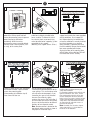
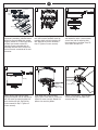
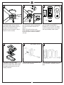
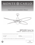
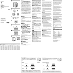
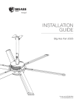
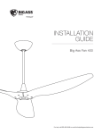
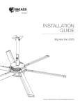
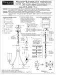
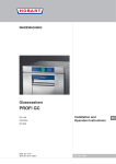
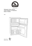
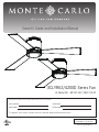
Owner’s Guide and Installation Manual
3CLYR52/42XXD Series Fan
UL Model NO. : MC1213-52 / MC1213-42
Attach sales receipt to this card and retain as your proof of purchase
DATE OF PURCHASE:
RETAILER NAME:
MODEL NUMBER:
RETAILER ADDRESS:
To register your fixture, please visit our website www.montecarlofans.com
3CLYR52XXD: 7.7 kgs/16.94 lbs
3CLYR42XXD: 6.7 kgs/14.74 lbs
Total fan weight with light kit
Cautions and Warnings
WARNING: TO REDUCE THE RISK OF FIRE, ELECTRIC SHOCK, OR INJURY TO PERSONS, OBSERVE THE FOLLOWING
READ AND SAVE THESE INSTRUCTIONS
Installation work and electrical wiring must be done by qualified person(s) in accordance with applicable codes and standards (ANSI/NFPA
70-1999), including fire-rated construction.
Use this unit only in the manner intended by the manufacturer. If you have any questions contact the manufacturer.
After making the wire connections, the wires should be spread apart with the grounded conductor and the equipment-grounding conductor
on one side of the outlet box and ungrounded conductor on the other side of the outlet box. The splices, after being made, should be
turned upward and pushed carefully up into the outlet box.
WARNING: Before you begin installing the fan, servicing or cleaning unit, Switch power off at Service panel and lock service disconnecting
means to prevent power from being switched on accidentally. When the service disconnecting means cannot be locked, securely fasten a
prominent warning device, such as a tag, to the service panel.
Be cautious! Read all instructions and safety information before installing your new fan. Review the accompanying assembly diagrams.
When cutting or drilling into wall or ceiling, do not damage electrical wiring and other hidden utilities.
Make sure the installation site you choose allows the fan blades to rotate without any obstructions. Allow a minimum clearance of 7 feet
from the floor to the trailing edge of the blade.
WARNING: To Reduce The Risk Of Fire, Electric Shock, or Personal Injury, Mount To Outlet Box Marked “Acceptable for Fan Support of
15.9 kg (35 lbs) or less” And Use Mounting Screws Provided With The Outlet Box.
CAUTION: For Compliance with Local Codes and Regulations, If Installing The Secondary Support Safety Cable in the U.S., Do Not Remove
Knockouts In The Outlet Box. Mount the secondary support safety cable through the reserved nail/screw hole on the outlet box to the
building structure (or the ceiling joist).
WARNING: To reduce the risk of personal injury, do not bend blade holders during installation to motor, balancing or during cleaning. Do
not insert foreign object between rotating blades.
Attach the mounting bracket using only the hardware supplied with the outlet box.
WARNING: To reduce the risk of fire or electric shock, this fan must be installed with an isolating wall control/switch.
WARNING: To reduce the risk of fire or electric shock, this fan should only be used with fan speed control part no. 7083R manufactured
by Rhine Electronic Co., Ltd.
WARNING: To reduce the risk of fire or electric shock, do not use this fan with any other solid state fan speed control device, or variable
speed control.
If this unit is to be installed over a tub or shower, it must be marked as appropriate for the application.
Never place a switch where it can be reached from a tub or shower.
The combustion airflow needed for safe operation of fuel-burning equipment may be affected by this unit’s operation. Follow the heating
equipment manufacturer’s guideline safety standards such as those published by the National Fire Protection Association (NFPA), and the
American Society for Heating, Refrigeration and Air Conditioning Engineers (ASHRAE) and the local code authorities.
CAUTION: To Reduce the Risk of Electric Shock, Disconnect the electrical supply circuit to the fan before installing the light kit.
All set screws must be checked and tightened where necessary before installation.
Tools Required for Assembly (not included): Electrical Tape, Phillips Screwdriver, Pliers, Safety Glasses, Stepladder and Wire Strippers
Customer Service
800-969-3347
Customer Service Center
7400 Linder Ave.
Skokie, IL 60077
www.montecarlofans.com
© 2013 Monte Carlo Fan Company
2
4/25/2013
1
2
ON
ON
OFF
OFF
Before you begin installing the fan, Switch
power off at Service panel and lock
service disconnecting means to prevent
power from being switched on
accidentally. When the service
disconnecting means cannot be locked,
securely fasten a warning device, such
as a tag, to the service panel.
3
Mounting plate
Before installing this fan make sure the
outlet box is properly installed to the
house structure. To reduce the risk of
fire, electric shock, or personal injury,
mount to outlet box or supporting system
acceptable for fan support.
(Mounting must support at least 35 lbs.)
Use metal outlet box suitable for fan
support and use only the screws provided
with the outlet box (must support 35
lbs). Before attaching fan to outlet box,
ensure the outlet box is securely fastened
by at least two points to a structural
ceiling member ( a loose box will cause
the fan to wobble). Remove the two outlet
box screws provided with the box,
aligning the holes of the mounting plate
with the holes of the outlet box. Reinstall
the 2 outlet box screws securely.
3
4
5
6
Hook
Lag
Safety
screw
cable
ON
Dip switches
Washer
Lock washer
Loosen 2 screws across from each other
and remove the other 2 preassembled
screws from mounting plate
(Corresponding to installation step 8).
Save screws for later use.
© 2013 Monte Carlo Fan Company
Set dip switches on the Remote
Transmitter and Remote Receiver to the
same settings. This must be done so the
units will communicate properly. If you
have other fans you can set to control
from one Transmitter by setting
receivers the same as the Transmitter. If
you have more than one fan with remote,
you can set the dip switches to different
positions to have separate control.
Note: Remote receiver is located on the
top plate of motor assembly as shown in
the graphic of installation step 7.
3
Hang motor assembly onto the hook on
mounting plate for hands-free wiring and
safety cable installation.
For Canadian installation and for USA fan and
light kit combinations over 35 lbs, in both
flush and downrod modes the safety cable
must be installed into the house structure
beams using 3” lag screws, washers and lock
washers provided. Make sure that when the
safety cable is fully extended the lead wires
are longer than the cable and no stress is
placed on the lead wires.
Note: If Installing The Secondary Support
Safety Cable in the U.S., Do Not Remove
Knockouts In The Outlet Box.
4/25/2013
7
8
Ground/Green
White
Black
Power
source
Wall
switch
9
Driver
Receiver
Capacitor
Make wiring connections using wire
connectors provided as indicated above.
White from house to White from remote
receiver marked AC N. Black from house
to Black from remote marked AC L.
Connect all green grounded wires to
Grounded wire from House. Make sure
that no filaments are outside of the wire
connector.
Lift motor assembly, aligning the keyhole
slots with the preassembled screws on
mounting plate, and twist clockwise till
lock. Reinstall the screws removed in
step 4. Tighten all screws securely.
Loosen 2 screws across from each other
and remove the other 2 preassembled
screws from side of mounting plate
(corresponding to installation step 10).
Save screws for later use.
10
11
12
Housing
Plate on motor
Blade
Attach housing onto mounting plate,
aligning the keyhole slots on the housing
with the screws on mounting plate and
twist clockwise till tight. Reinstall the
screw removed in step 9. Tighten all
screws securely.
© 2013 Monte Carlo Fan Company
Install blade with screws provided,
aligning each of the holes as shown and
tighten all screws securely. Repeat this
process for remaining blades.
4
Loosen 2 and remove 1 preassembled
screw from the plate on motor. Save
screw for later use.
4/25/2013
13
14
Blue
White
15
White
Black
Battery cover
Light pan
Battery
LED light kit
Attach light pan onto the plate on motor,
aligning the keyhole slots on the light
plate with the preassembled screws on
the plate. Twist clockwise till lock.
Reinstall the screw removed in step 12.
Tighten all screws securely.
16
HAND HELD INSTALL
Place battery cover over battery
compartment and buttons. Place remote
over 2 pins on front cover. Attach cover
of remote by placing over 4 pins and
snapping into place.
© 2013 Monte Carlo Fan Company
Connect white wire from fan to white wire
from LED light kit and then connect blue
wire from fan to black wire from LED
light kit.
Attach LED light kit to light pan by
locating dimples in light pan with grooves
on the LED light kit and twist clockwise
until tight.
Remove battery cover. Install 12V battery
into wall remote. Duracell MN21 /
Evereday A23 / GP 23A all 12V. Attach
cover of remote by placing over buttons
and snap the battery cover in place.
17
18
WALL MOUNT INSTALL
Install wall control unit to outlet box using
machine screws provided.
5
Attach front cover to wall control unit with
screws provided. Snap battery cover in
place
4/25/2013
Remote Control Transmitter Features
MEDIUM SPEED
FAN REVERSE (Press
once to change direction
of the fan) Fan must be
running to reverse.
LED LIGHT
HIGH SPEED
LOW SPEED
LIGHT ON/OFF SETTING
AND DIMMER (Press and
hold to dim light infinitely)
FAN OFF SETTING
(Turn fan off only)
FAN SPEED: Depress “1 dot” for low speed, “2 dots” for medium or “3 dots” for high. To turn fan off press square”.
LIGHT DIMMER: To turn light on, press light dimmer once quickly. To turn off press once quickly while light is on. To dim light
hold down button “light dimmer”. The light will cycle from bright to dim to bright until button is released. Light will maintain last
setting if turned off.
FORWARD/REVERSE: Depress reverse button with fan running. Allow a few seconds for fan to slow down and change rotation
direction. Clicking noise may be heard after depressing button.
Note: If not using for long periods of time, remove battery to prevent damage to remote transmitter, and store the remote
transmitter away from excess heat or humidity
© 2013 Monte Carlo Fan Company
6
4/25/2013
Trouble Shooting
,I\RXKDYHGLI¿FXOW\RSHUDWLQJ\RXUQHZFHLOLQJIDQLWPD\EHWKHUHVXOWRILQFRUUHFWDVVHPEO\LQVWDOODWLRQ
RUZLULQJ,QVRPHFDVHVWKHVHLQVWDOODWLRQHUURUVPD\EHPLVWDNHQIRUGHIHFWV,I\RXH[SHULHQFHDQ\IDXOWV
SOHDVHFKHFNWKLV7URXEOH6KRRWLQJ&KDUW,IDSUREOHPFDQQRWEHUHPHGLHGRU\RXDUHH[SHULHQFLQJGLI¿FXOW\LQ
LQVWDOODWLRQSOHDVHFDOORXU&XVWRPHU6HUYLFH&HQWHUDWWKH
QXPEHUSULQWHGRQ\RXUSDUWVOLVWLQVHUWVKHHW
Warning %HIRUH VHUYLFLQJ RU FOHDQLQJ XQLW 6ZLWFK SRZHU RII DW 6HUYLFH SDQHO DQG ORFN VHUYLFH GLVFRQQHFWLQJ
PHDQVWRSUHYHQWSRZHUIURPEHLQJVZLWFKHGRQDFFLGHQWDOO\:KHQWKHVHUYLFHGLVFRQQHFWLQJPHDQVFDQQRWEH
ORFNHGVHFXUHO\IDVWHQDSURPLQHQWZDUQLQJGHYLFHVXFKDVDWDJWRWKHVHUYLFHSDQHO
Trouble
Suggested Remedy
,IIDQGRHVQRWVWDUW
&KHFNPDLQDQGEUDQFKFLUFXLWIXVHVRUFLUFXLWEUHDNHUV
&KHFNOLQHZLUHFRQQHFWLRQVWRIDQDQGVZLWFKZLUHFRQQHFWLRQVLQVZLWFKKRXVLQJ
CAUTION0DNHVXUHPDLQSRZHULVWXUQHGRII
,I WKLV IDQ XVHV PDQXDO IRUZDUGUHYHUVH VZLWFK PDNH VXUH WKH VZLWFK LV SXVKHG ¿UPO\
HLWKHUZD\)DQZLOOQRWRSHUDWHZKHQVZLWFKLVLQWKHPLGGOH
,IWKLVIDQXVHVUHPRWHFRQWUROOHUPDNHVXUHGLSVZLWFKHVDUHVHWWLQJSURSHUO\DQGPDNH
VXUHEDWWHU\LVHIIHFWLYH
,IIDQVRXQGVQRLV\
&KHFNWRPDNHVXUHDOOVFUHZVLQPRWRUKRXVLQJDUHVQXJQRWRYHUWLJKWHQHG
&KHFNWRPDNHVXUHWKHVFUHZVZKLFKDWWDFKWKHIDQEODGHKROGHUWRWKHPRWRUDUHWLJKW
&KHFNWRPDNHVXUHZLUHQXWFRQQHFWRUVLQVZLWFKKRXVLQJDUHQRWUDWWOLQJDJDLQVWHDFK
RWKHURUDJDLQVWWKHLQWHULRUZDOORIWKHVZLWFKKRXVLQJ
CAUTION0DNHVXUHPDLQSRZHULVWXUQHGRIIEHIRUHHQWHULQJVZLWFKKRXVLQJ
&KHFNWREHVXUHOLJKWEXOELVWLJKWLQVRFNHWDQGQRWWRXFKLQJWKHJODVVVKDGH
6RPHIDQPRWRUVDUHVHQVLWLYHWRVLJQDOVIURP6ROLG6WDWHYDULDEOHVSHHGFRQWUROV
$OORZEUHDNLQSHULRGRIKRXUV0RVWQRLVHVDVVRFLDWHGZLWKDQHZIDQZLOOGLVDSSHDU
DIWHUWKLVSHULRG
,IIDQZREEOHV
,I WKLV LV D GRZQURG PRXQW IDQ PDNH VXUH WKH ULGJH RQ PRXQWLQJ EUDFNHW HQJDJHV WKH
QRWFKLQWKHGRZQURGEDOO
0DNH VXUH WKDW FDQRS\ PRXQWLQJ EUDFNHW RU PRXQWLQJ SODWH DUH WLJKWHQHG VHFXUHO\ WR
FHLOLQJMXQFWLRQER[DQGMXQFWLRQER[LVPRXQWHG¿UPO\WRFHLOLQJMRLVW
&KHFNWKDWDOOEODGHVDUHVFUHZHG¿UPO\LQWREODGHKROGHUV
&KHFNWKDWDOOEODGHKROGHUVDUHWLJKWHQHGVHFXUHO\WRPRWRU
0RVWIDQZREEOHSUREOHPVDUHFDXVHGZKHQEODGHOHYHOVDUHXQHTXDO&KHFNWKLVOHYHOE\
VHOHFWLQJ D SRLQW RQ WKH FHLOLQJ DERYH WKH WLS RI RQH RI WKH EODGHV 0HDVXUH WKLV GLVWDQFH
IURPEODGHWLSWRFHLOQJ.HHSLQJPHDVXUHZLWKLQURWDWHWKHIDQXQWLOWKHQH[WEODGH
LV SRVLWLRQHG IRU PHDVXUHPHQW 5HSHDW IRU HDFK EODGH ,I DOO EODGH OHYHOV DUH QRW HTXDO
\RXFDQDGMXVWEODGHOHYHOVE\WKHIROORZLQJSURFHGXUH7RDGMXVWDEODGHWLSGRZQLQVHUW
D ZDVKHU QRW VXSSOLHG EHWZHHQ WKH EODGH DQG EODGH KROGHU DW WKH VFUHZ FORVHVW WR WKH
PRWRU7RDGMXVWDEODGHWLSXSLQVHUWZDVKHUQRWVXSSOLHGEHWZHHQWKHEODGHDQGEODGH
KROGHU DW WKH WZR VFUHZV IDUWKHVW IURP WKH PRWRU 5HYHUVH WKH SRVLWLRQ RI WKH ZDVKHU LI
EODGHVPRXQWIURPWRSRIEODGH
,IEODGH ZREEOH LV VWLOO QRWLFHDEOHLQWHUFKDQJLQJWZR DGMDFHQWVLGH E\VLGH EODGHVFDQ
UHGLVWULEXWHWKHZHLJKWDQGSRVVLEO\UHVXOWLQVPRRWKHURSHUDWLRQ
,IOLJKWGRHVQRWZRUN &KHFNEOXHZLUHIURPIDQWRPDNHVXUHLWLVFRQQHFWHGWRKRWZLUHIURPKRXVH
&KHFNIRUORRVHRUGLVFRQQHFWHGZLUHVLQIDQVZLWFKKRXVLQJ
&KHFNIRUORRVHRUGLVFRQQHFWHGZLUHVLQOLJKWNLW
&KHFNIRUIDXOW\OLJKWEXOEDQGPDNHVXUHEXOELVWLJKWLQVRFNHW
5HPRYHOLJKWNLWDQGFKHFNWKHSOXJFRQQHFWLRQVLIWKH\DUHSUHVHQW
,IWKLVIDQXVHVUHPRWHFRQWUROOHUPDNHVXUHGLSVZLWFKHVDUHVHWWLQJSURSHUO\DQGPDNH
VXUHEDWWHU\LVHIIHFWLYH
CAUTION 0DNH VXUH PDLQ SRZHU LV WXUQHG RII EHIRUH HQWHULQJ VZLWFK KRXVLQJ DQGRU
FDQRS\
© 2013 Monte Carlo Fan Company
7
4/25/2013
Apr.2013