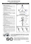
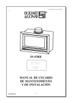
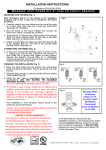
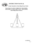
1
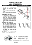
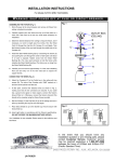
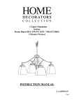
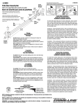
INSTALLATION INSTRUCTIONS
For Model # 27012 (REV.12/01/2003)
WARNING!
S H U T P O W E R O F F AT F U S E O R C I R C U I T B R E A K E R .
ASSEMBLING THE FIXTURE (Fig. 1)
1. Carefully remove the fixture from the carton and check that all
parts are included as shown in the illustration.
2. Shut off power at the circuit breaker and remove old fixture
including the crossbar.
3. Adjust Arm (A) to proper position
4. Place the Shade (F) over Glass Ring (G).
5. Bring the Glass Ring (G) and the Shade (F) to match with the
screw holes on Arm (A)
6. Secure the combination (G) (F) and (A) by using Stud (E) and
tighten with Decorative Nut (D).
7. Place Lamp Shade (C) over the Light Socket on Arm (A).
8. Secure the Lamp Shade (C) with Screw Shell (B)
9. Repeat assembly on the other side.
10. Install Light bulbs in accordance with the fixture’s
specifications. (DO NOT EXCEED THE MAXIMUM
WATTAGE RATING).
HANGING THE FIXTURE (Fig. 2)
11. Thread Nipple into Loop until snug.
12. Thread other end of Nipple with Loop attached into crossbar
until snug.
13. Place Lock Washer over end of Nipple protruding through
crossbar and thread Hex Nut onto nipple until tight.
14. Take this crossbar assembly and mount to ceiling junction
box with junction box screws. Tighten screws securely with
screwdriver.
15. By measuring determine correct number of links needed for
proper hanging height.
16. Use a pair of pliers to open one end link of the chain, attach
the chain to the fixture’s loop, and close the link. Slip Loop
Collar and Canopy over the chain.
17. Open the other end link of the chain and lift the fixture to
attach to the ceiling loop, close the chain link.
18. Lace the fixture’s wires through the chain links and pull until
taut. Feed the fixture wires through the Loop and Nipple and
pull until taut.
CONNECTING THE WIRES (Fig. 3)
19. At this point, connect the electrical wire as shown in figure 3,
making sure that all wire connectors are secured. If your
outlet has a ground wire (green or bare copper), connect the
fixtures Ground Wire to it. Otherwise, connect the fixture
Ground Wire directly to the crossbar using the Green Screw
provided.
20. Tuck these wire connections neatly into the ceiling junction
box and then raise the canopy all the way to the ceiling.
Raise the Lock Collar and thread onto ceiling Loop protruding
through canopy.
Your installation is now complete. Return power to the
junction box and test the fixture.
Fig. 1
A
B
C
D
E
F
G
Fig. 2
Junction Box
(Ceiling)
Hex Nut
Lock Washer
Crossbar
Screw
Nipple
Loop
Chain
Canopy
Lock Collar
A
Fig. 3
FIXTURE
WIRES
Black or
Smooth
FIXTURE
WIRES
White or
Ribbed
FIXTURE
WIRES
Bare
Copper
(Ground)
In the event that you should have any installation question or are missing
parts, please contact Customer Service. Customer service may be reached
weekdays a 1-800-527-0998 between the hours of 8:00am and 5:00pm PST
(Pacific Standard Time).
Notice: It is important to use proper chain pliers (not included)
To OPEN and CLOSE the chain included with this fixture. Do
not open them with other tools that may twist or stress the
chain links. It is important to use proper chain pliers like the
ones shown in the diagram.
LA-740E/S
INSTRUCCIONES PARA LA INSTALACION
Para Modelo # 27012 (REV.11/21/2003)
ADVERTENCIA! CORTE LA CORRIENTE DESDE EL FUSIBLE O EL INTERRUPTOR
ENSAMBLAJE DE LA LAMPARA (Fig. 1)
1. Desempaque cuidadosamente su nueva lampara y coloque
todas las partes en una superfice despejada.Tenga cuidado
de no perder las partes pequeñas que son necesarias para
la instalacion.
2. Corte la corriente en el circuito principal y saque la lampara
vieja incluyendo la barra transversal.
3. Ponga la postura de los brazos de la lampara (A) a la
posicion apropida
4. Ponga la Pantalla de Vidrio (F) sobre el Marco (G).
5. Levante el Marco (G) y junte la Pantalla de Vidrio (F) para
que los abujeros del Brazo (A) esten aliniados.
6. Asegure las combinaciones (G) (F) y (A) usando el Techon
(E) y la Tuerca Decorativa (D).
7. Ponga la Pantalla de Vidrio (C) sobre los Sockets
8.
Asegure la Pantalla de Vidrio (C) sobre los Socket con el Anillo
del Socket (B).
9.
Repita el mismo processo con el otro lado.
10. Instale los focos de acuerdo a las especificaciones.
NO
EXCEDA MAS DE LOS VATIOS ESPECIFICADOS!!
MONTANDO LA LAMPARA (Fig. 2)
11. Atornille la Boquilla con la Argolla hasta que quede bien
apretada.
12. Atornille la otra punta de la Boquilla a la argolla unida a la
Barra Transversal hasta que quede apretada.
13. Coloque la Rondana sobre la punta de la Boquilla que
aparece a traves de la barra transversal y asegurela con la
Tuerca Hexagonal.
14. Tome el asemblaje de la barra transversal y montelo a la
caja de union del techo use los tornillos de la caja de Union,
apriete bien los Tornillos.
15. Mida y determine la cantidad correcta de eslabones que
necesita para colgar la lampara a una altura apropiada.
Con las pinzas, desconecte y descarte la cadena sobrante.
16. Use unas pinzas para abrir una punta del eslabon de la
cadena, y conectela a la argolla de la Lampara. Cierre el
eslabon. Pase los alambres por entre los eslabones de la
cadena. Deslize el collar de la Argollay la Cubierta sobre la
cadena.
17. Habra el eslabon de la otra punta de la cadena y cuelge la
lampara de la argolla en el techo, cierre el eslabon.
18. Pase los alambres por la Argolla y la Boquilla hasta que
queden estirados.
CONECTANDO LOS ALAMBRES (Fig.3)
19. Conecte el alambrado electrico como se muestra en la
(Fig.3), use un conector de plastico para asegurar la
conexion. Si su caja de union tiene un alambre de tierra
(verde o de cobre), conectelo al alambre de tierra de la
lampara. Si no tiene, entonces conecte el alambre de tierra
de la lampara directamente a la barra transversal usando el
tornillo verde incluido.
20. Meta ordenamente las conexiones a la caja de union y
despues levante la Cubierta y peguela a la parte de la
argolla que sobresale a traves de la Cubierta.
Su instalacion a terminado, conecte la corriente electrica y
pruebe la lampara.
Fig. 1
A
B
G
C
D
E
F
G
Fig. 2
Caja de Union
(Techo)
Tuerca Hexagonal
Rondana
Barra Transversal
Tornillo
Boquilla
Argolla
Cadena
Cubierta
Collar de la Argolla
Alambre
Fig. 3
ALAMBRES
DE LA
LAMPARA
VERDE O DE
COBRE
(A TIERRA)
ALAMBRES
DE LA
LAMPARA
BLANCO O
CON MARCA
ALAMBRES
DE LA
LAMPARA
NEGRO O
SIN MARCA
ALAMBRES
DE LA
CASA
NEGROS
(CON CORRIENTE)
ALAMBRES
DE LA
CASA
BLANCO
(NEUTRAL)
ALAMBRES
DE LA
CASA
VERDE O DE COBRE
(A TIERRA)
En caso de preguntas sobre la instalacion o le
faltaron partes, porfavor hablar al departamento
de Servicio al Cliente al 1-800-527-0998 de
Lunes a Viernes de 8:00 a.m. a 5:00 p.m. PST
(Tiempo del Pacifico).
Nota: Es importante utilizar alicates de cadena (no incluidas)
Para abrir y cerrar la cadena incluida con este escantillón. No las
abras con otro instrumento que pueda torcer o marcar la cadena.
Es importante utilizar alicates de cadena como las que se muestran
en el diagrama.
LA-740E/S