1
INSTRUCTIONS MANUAL
4-Light Semi-Flush Mount Fixture
Menlo Park Collection
HOME DEPOT SKU N2008 (UPC 887016005840 )
Brushed Nickel Finish
Page 1
Thank you for purchasing this Hampton Bay Semi-Flush Mount
Fixture. This product has been manufactured with the highest standards
of safety and quality.
FEATURES:
1. Easy to install.
2. For energy savings this fixture has been engineered to safely use a
Self Ballasted Compact Fluorescent Lamp in place of an incandescent
lamp.
QUESTIONS, PROBLEMS, MISSING PARTS:
Before returning to your local Home Depot, please call our Customer
Service Team at 1-877-527-0313 or visit www.homedepot.com. Please
reference your SKU (N2008) or UPC (887016005840).
Page 2
WARNING
BECAUSE FAILURE TO COMPLY CAN LEAD TO INJURY:
1. Before starting installation of this fixture or removal of a previous
fixture, disconnect the power by turning off the circuit breaker or by
removing the fuse at the fuse box.
2. CONSULT A QUALIFIED ELECTRICIAN IF YOU HAVE ANY
ELECTRICAL QUESTIONS. If you have any non-electrical
questions about this fixture, please call our Customer Service Team
at 1-877-527-0313 or visit www.homedepot.com. Please reference
your SKU (N2008) or UPC (887016005840).
3. KEEP your receipt and these Instructions for Proof of Purchase.
TOOLS REQUIRED FOR INSTALLATION AND ASSEMBLY
(not included):
Phillips Screwdriver
Ladder
Light Bulb (x4)
(60 watt maximum)
Flathead
Screwdriver
Safety
goggles
Wire
Cutters
Electrical
Tape
Wire
Strippers
Pliers
Page 3
PARTS INCLUDED FOR ASSEMBLY (parts are not to scale):
1 ea Shade (# 2)
1 ea Metal Pad
(# 5)
1 ea Acrylic Pad (#4)
1 ea Top Frame
(#8)
1 ea Hex Nuts
(#3)
1 ea Bottom Frame
(#9)
1 ea Main Fixture
Body (#1)
4 ea Screws
(# 7)
1 ea Finial
(# 6)
1 ea “L” Phillips
Screwdriver (# 24)
ASSEMBLY INSTRUCTIONS:
1. Carefully unpack the fixture. Lay out all parts on a clean surface.
2. Attach the Top Frame (#8) to the Shade (#2), as shown.
3. Install incandescent Light Bulbs (not provided) into the sockets of the Main Fixture
Body (#1). Do not exceed a 60 watt incandescent light bulb. (Fig. 1)
4. The Shade (#2) should be fastened into the Main Fixture Body (#1), and secured with Screws
(#7); using a Phillips Screwdriver (# 24), as shown (Fig.2). Thread a Hex Nut (#3) onto the
Nipple on the Main Fixture Body(#1). Adjust the Hex Nut (#3) to the desired height. Place
the Bottom Frame (#9) and the Acrylic Pad (#4) over the Main Fixture Body (#1), making
sure the Nipple feeds through the center hole of the Acrylic Pad (#4), and then secure them
with the Metal Pad and the Finial (#6) .
Page 4
ASSEMBLY:
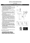
Fig. 1
(10#) Canopy
(#1) Main Fixture Body
(#7) Screw
Light Bulb
(#3) Hex Nut
(#8) Top Frame
(#2) Shade
(#9) Bottom
Frame
(#4) Acrylic Pad
(#5) Metal Pad
(#6) Finial
Fig. 2
Page 5
PARTS INCLUDED FOR INSTALLATION (parts are not to
scale):
2 ea End Caps
(#11)
1 ea Mounting Plate (#15)
2 ea Hex Nuts
(#12)
2 ea Fixture Mounting
Screws (#13)
2 ea Mounting
Screws (#14)
3 ea Wire Connectors (#16)
INSTALLATION INSTRUCTIONS:
1. Thread the Fixture Mounting Screws (#13) into the provided holes of the Mounting Plate (#15),
as shown. Thread the Hex Nuts (#12) onto the Fixture Mounting Screws (#13). Do not tighten
the Hex Nuts (#12) at this time.
2. Pull the power supply wires out of the Outlet Box, and attach the Mounting Plate (#15) to the
Outlet Box using the Mounting Screws (#14), as shown.
3. Attach the Black Supply Wire (A) to the Black Fixture Wire (A1) and the White Supply Wire
(B) to the White Fixture Wire (B1) using Wire Connectors (#16). Connect the Fixture Ground
Wire (C1) and the Supply Ground Wire (C) together using a Wire Connector (#16). Wrap all wire
connections with electrical tape for a more secure connection.
Note: Consult your local electrical code for approved grounding methods.
4. Carefully, tuck all the wires and wire connections into the Outlet Box. Place the Canopy (#10)
over the Outlet Box and onto the Fixture Mounting Screws (#13). Adjust the Fixture Mounting
Screws (#13) until they protrude out from the Canopy 1/4”. Remove the Canopy (#10) and secure
the position of the Fixture Mounting Screws (#13) by tightening the Hex Nut (#12) against the
Mounting Plate (#15). Place the Canopy (#10) back into the Fixture Mounting Screws (#13), and
secure it into place using the End Caps (#11) provided.
5. Installation is complete. Turn on power at the circuit breaker or fuse box. Turn the light switch
on to activate the fixture.
Page 6
INSTALLATION:
(#13) Fixture Mounting
Screw
(#15) Mounting Plate
(#14) Mounting
Screw
(#12) Hex Nut
(#10) Canopy
(#11) End Cap
Page 7
TROUBLESHOOTING:
Light will not turn on.
Fuse blows or circuit
breaker trips when light is
turned on.
Possible Cause
Corrective Action
1. Power is off.
1. M ake sure p ower sup p ly is on.
2. Fault y swit ch.
2. Test or rep lace swit ch.
3. Faulty wire connection
3. Check wiring.
Crossed wires or power wire is
grounding out.
Check wire connections.
PRODUCT MAINTENANCE:
1. To clean the outside of the fixture, use a dry or slightly dampened clean cloth (use clean
water, never a solvent) to wipe the surface of the fixture.
2. To clean the inside of the fixture, first disconnect power to the fixture by turning off the
circuit breaker or by removing the fuse at the fuse box. Next, use a dry or slightly
dampened clean cloth (use clean water, never a solvent) to wipe the interior surface of
the fixture.
3. Do not use any cleaners with chemicals, solvents or harsh abrasives. Use only a dry soft
cloth to dust or wipe carefully.
LIMITED WARRANTY
The manufacturer warrants this lighting fixture to be free from defects in materials and workmanship for a
period of five (5) years from date of purchase. This warranty applies only to the original consumer
purchaser and only to products used in normal use and service. If this product is found to be defective, the
manufacturer’s only obligation, and your exclusive remedy, is the repair or replacement of the product at
the manufacturer’s discretion, provided that the product has not been damaged through misuse, abuse,
accident, modifications, alterations, neglect or mishandling. This warranty shall not apply to any product
that is found to have been improperly installed, set-up, or used in any way not in accordance with the
instructions supplied with the product. This warranty shall not apply to a failure of the product as a result of
an accident, misuse, abuse, negligence, alteration, or faulty installation, or any other failure not relating to
faulty material or workmanship. This warranty shall not apply to the finish on any portion of the product,
such as surface and/or weathering, as this is considered normal wear and tear. The manufacturer does not
warrant and specially disclaims any warranty, whether expressed or implied, of fitness for a
particular purpose, other than the warranty contained herein. The manufacturer specifically
disclaims any liability and shall not be liable for any consequential or incidental loss or damage,
including but not limited to any labor/expense costs involved in the replacement or repair of said
product.
Page 8