1
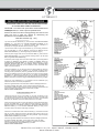
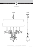
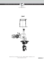
DECORATIVE ACCESSORIES AND ACCENT FURNITURE
MANUFACTURERS OF WALL DECOR, LIGHTING,
UTTERMOST
P O B O X 5 5 8 /3 3 2 5 G RA S S Y HILL RD. RO C KY MO UNT, VIR G INI A 24151
www.u t t e r m os t .co m
DECORATIVE ACCESSORIES AND ACCENT FURNITURE
MANUFACTURERS OF WALL DECOR, LIGHTING,
UTTERMOST
INSTALLATION INSTRUCTIONS
.
PLEASE READ CAREFULLY AND SAVE THESE INSTRUCTIONS,
AS YOU MAY NEED THEM AT A LATER DATE.
CAUTION – Turn off the main power at the circuit breaker before
installing the fixture, in order to prevent possible shock.
Remove the fixture and the mounting package from the box and
make sure that no parts are missing by referencing the
illustrations on the installation instructions.
FOR WALL MOUNT (Fig. 1 & 2)
1.A) Place the #8-32 HEX NUTS (5.) onto the #8-32 FIXTURE MOUNTING
SCREWS (7.), and attach the FIXTURE MOUNTING SCREWS to the
MOUNTING BRACKET (4.), or universal mounting plate (whichever is
provided). Do not tighten the HEX NUTS at this time. (Fig.4)
B) If the fixture uses a single 1/8” IPS NIPPLE (7.) for mounting, thread the
1/8” IPS HEX NUT (5.) onto the NIPPLE, and screw the NIPPLE into the
MOUNTING BRACKET (4.), without tightening the HEX NUT. (Fig.2)
2.Pull the power supply wires out from the OUTLET BOX (3.), and mount the
MOUNTING BRACKET (4.) or the universal mounting plate to the OUTLET
BOX, using MOUNTING SCREWS (6.)
3. Attach the power supply wires to the fixture lead wires by connecting BLACK
to BLACK (or SMOOTH), and WHITE to WHITE (or RIBBED). Attach the
POWER SUPPLY GROUND WIRE (11.) from the OUTLET BOX (3.). connect
FIXTURE GROUND WIRE (12.) and POWER SUPPLY GROUND WIRE
together using the correct size of wire connectors. Place connected wires
inside of the OUTLET BOX.
4.Place the CANOPY (14.) on the fixture over the OUTLET BOX (3.) and onto
the fixture mounting screws [or NIPPLE (7.)], and adjust the #8-32 fixture
mounting screws (or NIPPLE ) until they protrude out from the CANOPY 1/4”.
Remove the CANOPY and secure the position of the fixture mounting screws
(or NIPPLE) by tightening the HEX NUT (S) (5.) against the MOUNTING
BRACKET (4.). Place the CANOPY back onto the fixture mounting screws, (or
NIPPLE), and secure into place using the DECORATIVE NUTS (15.) provided.
1.TOP COVER
2.DECORATIVE SCREWS
3.OUTLET BOX
4.MOUNTING BRACKET
5.#8-32 IPS HEX NUT
6.MOUNTING SCREWS
7.FIXTURE MOUNTING SCREW
8.WHITE TO WHITE WIRE CONNECTION
9.CUPPED WASHER (if provided)
10.BLACK TO BLACK WIRE CONNECTION
11.POWER SUPPLY GROUND WIRE
12.FIXTURE GROUND WIRE
13.GROUND SCREW
14.CANOPY
15.DECORATIVE NUT
16.TAIL PIPE
17.TAIL SECTION
1.TOP COVER
2.DECORATIVE SCREWS
3.OUTLET BOX
4.MOUNTING BRACKET
5.1/8” IPS HEX NUT
6.MOUNTING SCREWS
7.NIPPLE
8.WHITE TO WHITE WIRE CONNECTION
9.CUPPED WASHER (if provided)
10.BLACK TO BLACK WIRE CONNECTION
11.POWER SUPPLY GROUND WIRE
12.FIXTURE GROUND WIRE
13.GROUND SCREW
14.CANOPY
15.DECORATIVE NUT
16.TAIL PIPE
17.TAIL SECTION
18.COUPLING
5.Screw the TALL SECTION (17.) (if provided) onto the COUPLING (18.)
located at the bottom of the lamp compartment.
6.Screw in light bulbs that do not exceed the maximum wattage specified on
the fixture’s wattage rating label, into the socket located inside the lamp
compartment. Place the lamp cover onto the top of the lamp compartment, and
secure in position using the decorative head screws provided.
INSTALLATION COMPLETED
FOR POST MOUNT (Fig. 3)
1.Place the fixture on the top of the POST (9.) on which the fixture is to be
mounted and position as desired. Using the holes located on the POST CAP
(3.) mark the hole position on the POST. Remove the fixture from the POST
and drill a 1/8” diameter hole at each marked position on the POST.
1.LAMP COVER
2.DECORATIVE HEAD SCRES
3.POST CAP
4.SHEET METAL SCREW
5.WHITE TO WHITE WIRE CONNECTION
6.BLACK TO BLACK WIRE CONNECTION
7.POWER SUPPLY GROUND WIRE
8.FIXTURE GROUND WIRE
9.POST
2.Pull the power supply wires out from the POST (9.) and the fixture lead wires
out from the POST CAP (3.), and attach the wires together by connecting
BLACK to BLACK (6.) and WHITE to WHITE (5.). Attach the POWER SUPPLY
GROUND WIRE (7.) to the FIXTURE GROUND WIRE (8.) using a wire
connector rated for the size of wires being connected.
3.Place the connected wires down inside the POST (9.), and mount the POST
CAP (3.) in place, aligning the holes in the POST CAP with the ones on the
POST. Secure the POST CAP to the POST using #10X1/2” long self-tapping
SHEET METAL SCREWS (4.) provided.
4.Screw a light bulbs that does not exceed the maximum wattage specified on
the fixture’s wattage rating label, into the lamp socket. Place the LAMP
COVER (1.) onto the top of the lamp compartment, and secure in position
using the DECORATIVE HEAD SCREWS (2.) provided.
INSTALLATION COMPLETED
P O B O X 5 5 8 /3 3 2 5 G RA S S Y HILL RD. RO C KY MO UNT, VIR G INI A 24151
www.u t t e r m os t .co m